Note: Descriptions are shown in the official language in which they were submitted.
CA 02132663 2000-10-20
1
DATA ENTRY KEYPAD ASSEMBLY
a) Field of the invention
The present invention relates to a data entry
keypad assembly for a system controlling a plurality of
components. More particularly, the data entry keypad
assembly is for a system controlling a plurality of
components having operational states which are displayed
by an array of lights, such as for example a security
system controller connected to a plurality of detectors
and sensors.
b) Brief description of the prior art
Known in the art, there is U.S. patent no.
5,264,825 to Schneider describing a combined switch and
indicator light assembly for an electronic vehicle
security system. This security system includes a central
controller having a plurality of sensors connected
thereto. These sensors are located throughout the vehicle
and generate signals sent to the controller when an
intrusion attempt into the vehicle is detected. The
security system is armed by using the aforesaid switch.
When armed, the light indicator of the combined switch and
indicator light assembly is on, and when the indicator
light is off the system is disarmed. Also, in response to
the signals generated by the sensors, the controller
activates an alarm device and indicates the intrusion
attempt by flashing the indicator light. This flashing
CA 02132663 2000-10-20
2
indicates that the intrusion attempt was detected during
the owner s absence.
The switch of the combined switch and indicator
light assembly exclusively disables the whole security
system, and individual component detector information is
neither displayed nor controlled.
Also known in the art are office telephone
systems wherein an arrangement of keys and associated LEDs
serve for indicating the state of all telephone lines
(i.e. busy or free) , and for directly connecting the user
to the free line desired when an associated key is
pressed. An example is the Inter-tel~mpkll by Inter-tel
Equipment Inc. of Phoenix, AZ. The illuminated keys of
such a conventional system cannot be used to enter data,
program the system or dial any number.
In the field of security system controllers,
conventional numeric keypads are provided which may
include additional function keys and may be provided with
backlighting in order to facilitate security code entry in
dim lighting. The protected zones of the security system
are represented by individual LEDs provided in an area
separate and usually adjacent the numeric data entry
keypad. Printed or handwritten identifiers may be
provided for labelling each of the LEDs by the associated
name of the detector zone. For presenting a convenient
and inconspicuous control panel, the labelled LEDs are
provided on a relatively small area in a condensed matrix.
Still, the overall size of the keypad controller is much
larger than the required area for the keypad alone.
OBJECTS AND SUMMARY OF THE INVENTION
CA 02132663 2000-10-20
3
It is an object of the present invention to
provide a data entry keypad assembly for a system
controlling a plurality of components having the necessary
means by which a user can enter data to control the system
and display the state thereof directly on the keypad
assembly.
According to the present invention there is
provided a data entry keypad assembly for a system
controlling a plurality of components. The keypad assembly
comprises a plurality of key zones arranged in an ordered
matrix and each having a label identifier, and a plurality
of key switches, provided in corresponding key zones. The
keypad assembly also comprises a plurality of light source
means, each one of the light source means also provided in
the corresponding key zones. Input controller means
connected to the key switches are provided for receiving
data in the form of a sequence of key presses of the
switches, and state information displaying means connected
to the light source means are provided for indicating a
state of at least some of the components each associated
with at least some of the label identifiers.
According to a preferred feature of the
invention, a light source used to identify the state in
one of the key zones provides back lighting for the key
zone and switch for use in dim lighting. In the case that
the light source is an LED, the intensity of the LED may
be varied by pulsing the LED with a variable duty cycle.
According to a further preferred feature of the
present invention, the keypad assembly is provided with
key zones which cover substantially the entire frontal
CA 02132663 2000-10-20
4
surface area of a control panel with the key switches
being enlarged sufficiently to facilitate data entry with
minimal error by accidentally missing one key for another.
The keypad according to the present invention is
preferably smaller than conventional system controller
keypads.
According to another preferred feature of the
present invention, there is provided a data entry keypad
assembly for a system controlling a plurality of
components and for displaying information about a state of
said components, the keypad assembly comprising: a keypad
panel having a plurality of key zones arranged in an
ordered matrix and each having a numeric component label
identifier associated with one of said components; an
integrated set of translucent key switches mounted to said
panel in each of said zones, said key switches comprising
a plurality of resilient mobile key members, at least one
of which having an electrical contact surface; a light
source provided in each one of said key zones; a plurality
of terminal contacts provided on a circuit board surface
around each said light source opposite each said
electrical contact surface; a state information display
control device connected to each said light source for
indicating a state of said components each associated with
the label identifiers.
According to still another preferred feature of
the present invention, there is provided a data entry
keypad assembly for a system controlling a plurality of
components, for entering numeric data and for displaying
information about a state of said components, the keypad
assembly comprising: a keypad panel having a plurality of
CA 02132663 2000-10-20
key zones arranged in a ordered matrix and each having a
numeric component label identifier associated with one of
said components; a key switch mounted to said panel in
each of said zones; a light source means provided in each
5 one of said key zones; input controller means connected to
said key switches for collecting, in a first state,
numeric data in the form of a sequence by key presses of
said switches provided in said key zones, and for
changing, in a second state, a state of one of said
components associated with said key zone in which said one
key switch is located by pressing said one key switch, and
state information displaying means connected to said light
source means for indicating a state of each individual one
of said components each associated with said label
identifiers by controlling an illumination state of each
individual one of said light source means.
According to another preferred feature of the
present invention, there is provided a keypad assembly for
a security system, said system having a plurality of
numbered security zones or detectors, comprising: a keypad
panel having an array of numbered keys; a key switch
associated with each of said numbered keys; means for
selectively and separately illuminating each key; and
control circuitry connected to said key switches for
obtaining, in a first mode of operation, numeric data from
key presses of said keys, and, in a second mode of
operation, for accepting a key press of one of said keys
as a command to change the state of the detector or
security zone corresponding to the key pressed, and for
activating said illumination means to selectively
illuminate each key having a number corresponding to a
CA 02132663 2000-10-20
6
detector or security zone whose state is to be indicated
by said illumination, whereby said keypad assembly is
capable of accepting commands and simultaneously
displaying the states of plural security zones or
detectors.
As can be understood, the present invention
facilitates interactive programming between the system and
the user as a result of individual control of the light
sources. For example, a light source may be flashed in
order to prompt the user to press the associated key in
order to receive state information. Non-state related
information can also be displayed by sequentially flashing
light sources. For example, after a new security code is
programmed, the system may sequentially flash the light
sources associated with the keys making up the security
code to remind the user of the security code chosen and
the sequential pattern it forms. It is also possible to
enter a command for system information which is stored
numerically and can be displayed for confirmation by
sequentially flashing numeric keys. For example, in the
case that the controller includes a real time clock, the
present setting of the real time clock can be displayed by
sequentially flashing a series of digits representing the
time. Such information display has further advantages.
For example, a system having a real time clock can record
the time of a state change. In the case of a security
alarm controller, the time at which an intrusion detector
detected an intrusion can be displayed by sequentially
flashing numeric keys in response to a control command
entered by the user.
CA 02132663 2000-10-20
7
When the data entry keypad assembly according to
the present invention is used for a security system, it
controls a plurality of detectors and warning devices, and
displays a detection state of the detectors, while
allowing activating/deactivating commands to be entered.
BRIEF DESCRIPTION OF THE DRAWINGS
FIG.1 is a block diagram of a data entry keypad
assembly according to the present invention, used in a
security system;
FIG.2 is a partial back view of a molded
silicone keypad block of the data entry keypad assembly;
FIG.3 is a cross section view showing key
switches provided in the corresponding key zones of the
data entry keypad assembly.
DETAILED DESCRIPTION OF THE PREFERRED EMBODIMENT
With reference to FIG.1 to FIG.3, there is shown
a security system data entry keypad assembly 18, connected
to CPU 32 for controlling different detectors gathered in
two separate groups, numbered 34 and 36, of a security
system 40. These detectors can be infrared or microwave
motion detectors, smoke detectors and glass break
detectors, as well as vibration/shock and door/window
contact sensors.
The keypad assembly 18, as shown, is provided
with eighteen key zones 10 arranged in an ordered matrix,
eighteen key switches 29 and light indicators 12, such as
LEDs and more specifically surface mount LEDs, arranged in
CA 02132663 2000-10-20
8
an ordered matrix in each of the key zones 10. However,
other light indicators than the LEDs can be used such as
conventional lamps of small sizes. The key switches 29 all
have a corresponding label identifier. As shown, the
various label identifiers are as follows: 2ND, TRBL, MEM,
BYP, CLEAR, ENTER, STAY, AWAY and the numerics 1 to 12.
The functions of all of the labeled key switches 29 of the
keypad assembly 18 will be described hereinafter.
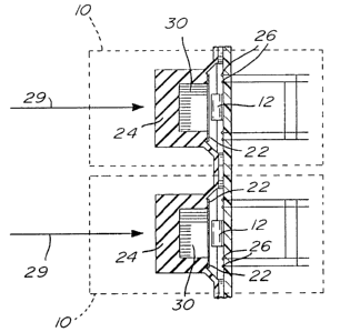
The eighteen key switches 29 include a molded
silicone keypad block having interconnected resilient
translucent mobile key elements 24, each having a
conductive contact surface 22. Four contact terminals 26
are provided on a surface (not shown), such as a PCB
(Printed Circuit Board), on which the surface mount LEDs
12 are mounted and located directly under the
corresponding contact surfaces 22. The translucent mobile
key elements 24 are each provided with a cavity 30 (see
Fig. 2) into which the low profile surface mount LEDs 12
fit when the key elements are depressed. In that way, the
LEDs 12 are able to transmit light through a middle of the
interconnected mobile key elements 24. Also, each contact
surface 22 allows a current to flow across the terminals
26 when the mobile key elements 24 are depressed.
It is worth mentioning that regular LEDs can be
mounted onto a LED board (not shown) in an ordered matrix.
Moreover, a contact terminal board provided with small
apertures aligned with the LEDs, can be mounted onto the
LED board so that at least part of each LED projects
upwardly from a contact terminal board's surface. In this
manner, when the keypad block is mounted on the contact
CA 02132663 2000-10-20
9
terminal board, at least part of each LED fits into the
cavity of each mobile key member.
The keypad assembly 18 is also provided with an
input controller 28 connected to the key switches 29 for
translating key presses into numerical data and sending
the data to the CPU 32. The data received is in the form
of a sequence of key presses of the switches 29. The
assembly 18 also has an information displaying controller
30 including for example, a matrix of conductors (not
shown) connected to the LEDs 12 for turning on individual
ones of the LEDs 12. An LCD 15 can also be connected to
CPU 32 for indicating the name of a security zone
(component of the system) corresponding to a depressed key
29 or an illuminated LED 12. The controller 30 receives
light state data from the CPU 32 for indicating a state of
the system and of the detectors in the two groups of
detectors, 34 and 36. The controller 30 also includes a
PWM (Pulse-Width Modulated) generator 31 which pulses the
LEDs 12 with a short duty cycle at a frequency appearing
continuous, providing a reduced amount of light when the
keys 29 are idle to make the key switches 29 visible in
low light conditions (i.e. back lighting). The duty cycles
of PWM signals are adjustable to adjust the level of the
reduced amount of light.
In operation, the user by pressing the key
switches 29 sends data, such as an access code or a
control command, to the input controller 28 which receives
it, and sends it to the CPU 32. For example, by pressing
the key switch 29 in a key zone 10 labeled MEM for 2
seconds, and then continuing pressing, the user can alter
the level of illumination (the backlighting cycles from
CA 02132663 2000-10-20
dimness to brightness). By stopping the pressing, the user
can select the desired level and then press the key switch
29 in the key zone 10 labeled ENTER or CLEAR to save it in
the CPU's 32 memory.
5 The keypad assembly 18 in the preferred
embodiment is for security system 40 which can provide
coverage for 24 security zones (two groups), such as
different locations in a house or a building, divided into
the aforesaid two groups, 34 and 36, identified by their
10 numerical labels 1 to 12 for each group. By pressing once
or twice the key switch 29 labeled 2ND, the controller 30
is instructed to display the status of the first group of
detectors 34 and of the status of the second group of
detectors 36 respectively. Furthermore, when the key
switch 29 labeled 2ND flashes, this indicates that the 12
security zones of the second group 36 are being displayed.
The security system 40 can be programmed to
cover a wide variety of security situations, some of them
are described hereinabove.
The first security situation is when the user
wants all the security zones to be protected. In order to
protect all the security zones, firstly, the light
indicator 16 has to be enabled. This light indicator 16 is
enabled when all the zones are closed. (All windows and
doors have to be closed, and there can be no movement in
areas monitored by motion detectors, if such detectors are
used). Once the light indicator 16 is on, the user can
enter a first predetermined code, and thereafter the key
switch in the key zone labeled ENTER (using the code, the
security system is programmed to activate all of the
detectors in the first or second group of detectors, 34 or
CA 02132663 2000-10-20
11
36 ). If a user makes a mistake in entering the
predetermined code, the keypad assembly 18 makes a beep
sound by means of a beep generator 42 provided with the
keypad assembly 18. Thereafter, he or she must press the
key switch in the key zone labeled CLEAR and re-enter the
code.
When the code has been correctly entered, the
light indicator 14 is enabled, and the light indicator 16
flashes during a delay exit period. This delay exit period
is programmed based on the time the user requires to exit
the protected area once all of the detectors are
activated.
The display screen 15 can also be used to
display prompting messages, such as "ENTER PASSCODE", and
confirmatory messages such as asterisks as each key of the
security or access code is pressed and text messages like
"ALL ZONES ACTIVATED" and/or "30 SECONDS UNTIL ACTIVATION,
PLEASE EXIT NOW". The display can be changed to count
down the remaining delay.
A second security situation is when the user
wants to stay on the premises and still be protected. This
can be accomplished by pressing the key switch 29 labeled
STAY and entering the predetermined code. Using the key
switch labeled STAY, the security system 40 is programmed
to activate some of the detectors in the group of
detectors, 34 or 36, located throughout the premises and
to leave others open. The text display 15 can also be
used to give instructions, such as "ACTIVATES ONLY SOME
ZONES" and "ENTER STAY CODE" when the STAY key is pressed.
A third security situation is when the user
wants to manually activate some security zones and leave
CA 02132663 2000-10-20
12
others open. This is accomplished with a key switch 29
labeled BYP. By pressing this key switch 29 labeled BYP
and the predetermined code, the LED 12 in that key zone
will illuminate and if the security zones are bypassed the
LEDs 12 in the key zones corresponding to the numerical
security zones will be illuminated. Thereafter, by
pressing once on one of the desired key switches labeled 1
to 12, representing the security zones, the user can leave
the corresponding zone open. By pressing the key switch in
the same key zone twice, the user can activate the
corresponding security zone. Also, as aforesaid, by
pressing the key switch labeled 2ND, the controller 30 is
instructed to display the status of another group of
detectors, and in a same manner the corresponding key
switches labeled 1 to 12, representing the second set of
security zones, can be used to leave open or to activate
the last.
After the user has entered the correct zone
bypass information, he has to press a key switch 29 in a
key zone labeled ENTER, this will illuminate the key zone
labeled BYP thereby indicating that the security zone has
been left open. If a mistake was made in entering the
number of the selected security zone, the user has to
press the key switch 29 in the key zone labeled CLEAR.
A fourth security situation is when the user
wants to leave the premises in a hurry and activate the
security zones without manually entering security zones to
be bypassed. By pressing the key switch in the key zone 10
labeled AWAY and entering a predetermined code, the
security system 40 will automatically bypass any open
security zones until the exit delay terminates, and
CA 02132663 2000-10-20
13
thereafter all of the unopened detectors will be
activated.
A fifth security situation is when the user
wants to activate all of detectors in the two groups of
detectors 34 and 36 without entering the predetermined
code. This is accomplished by pressing the key switch
labeled 10 for 2 seconds.
Now, the key switch labeled MEM, when
illuminated, indicates if any alarms were generated while
all of the detectors of the security system 40 were
activated. A record of all alarm situations that occurred
are stored in the security system's 40 memory. By pressing
this key switch, after all the security zones have been
opened, all the key switches representing the security
zones, 1 to 12, where the alarms were generated will be
illuminated.
Also, the key switch labeled TRBL, when
illuminated, indicates the presence of various trouble
conditions. By pressing the key switch labeled TRBL, the
last flashes and the key switches labeled 1 to 10 may
serve for viewing those trouble conditions. For example,
after the key switch labeled TRBL has been pressed, the
key switch labeled 1 if illuminated indicates if a battery
provided for a back-up current in the event of a power
failure is not connected to the security system' s control
panel 40 including the keypad assembly 18 or should be
replaced. The key switch labeled 3, when on, indicates
that AC power is not being supplied to the security
system's control panel 40 including the keypad assembly
18. The key switch labeled 4 indicates that one of the
CA 02132663 2000-10-20
14
warning devices 45, such as the siren, is not properly
connected to the CPU 32.
Trouble information can also be displayed on the
text display 15, such as "SIREN DISCONNECTED" General
alarm information can also be displayed on display 15,
such as "INTRUDER ALERT". If only one zone detects an
intruder, the text message could read "INTRUDER IN: SOUTH
ENTRANCE HALL", thus displaying directly the zone name
involved in the alarm. However, when more than one zone
is triggered, the zone name is displayed only in response
to pressing the corresponding zone key 29.
As can be apparent to those skilled in the art
various changes can be made to the keypad assembly 18 as
described hereinbefore. For example, instead of using the
aforesaid input controller 28, the key switches 29 could
be directly connected to the CPU 32. In that way, when the
user presses the key switches 29, data in the form of the
sequence of key presses can be directly send to the CPU
32. Furthermore, instead of using the aforesaid
information displaying controller 30, each of the surface
mount LEDs 12 of the matrix of LEDs could be individually
directly connected to the CPU 32. The latter could send
the light state data directly to the individual LEDs 12
for indicating the state of the system 40 and of the
detectors in the two group of detectors, 34 and 36. The
CPU 32 may also include the PWM generator 31 for pulsing
the LEDs 12 to provide the back lighting for the key
switches 29.
It is possible to provide two or more keypad
assemblies 18 in different locations of a building for the
security system 40. Furthermore, the keypad assembly 18
CA 02132663 2000-10-20
could be provided with additional key switches serving for
the same purpose as the key switch labeled 2ND, thereby
with only one keypad assembly 18, the security system 40
could provide coverage for more security zones, more
5 specifically 12 extra security zones can be covered per
one additional key switch.
Another variant to the keypad assembly 18, as
shown in figure l, is the number of key zones 10. For
example, the keypad assembly could be provided with a
10 lesser number of key zones, such as 10, or a greater
number of key zones, such as 32, depending on the number
of functions the user wishes to have, or the number of
security zones the user wants to cover.
As can be apparent there are various advantages
15 to the keypad assembly 18 as described hereinabove.
Besides being easy to operate, with many functions
accessible just by one key press, the keypad assembly is
extremely functional, communicates vital security or
operational state information directly on the keypad, and
thus without the need for an additional matrix display,
and is designed in a compact fashion to accommodate any
user. Furthermore, the keypad assembly by having an
adjustable illumination level, is easily visible
especially in emergency situations.
The keypad assembly according to the present
invention can also be used for air conditioning or climate
control systems in buildings or houses. For this purpose,
the key switches of the keypad assembly could be used, for
example, to select individual thermostats from a group of
thermostats, and to adjust their operating temperatures.
Moreover, the keypad assembly could be used for compact
CA 02132663 2000-10-20
16
telephones for homes or offices. In this case, the key
switches could be used to dial the desired telephone
numbers and to inform the user of the state of all
telephone lines (i.e. busy or free) directly on the
keypad. Also, after the user has been informed of the
state of all telephone lines, he or she, can be
automatically connected to the selected free line by
pressing the corresponding key switch. Display 15 could
be used to show a number dialed.
In connection to this, the keypad assembly can
also be used for bank of elevators. In this case, the key
switches can be used for displaying the state of all
available elevators (i.e. presently working or disabled),
for entering the access code, and selecting the ones the
user wishes to turn off or on.
Although the present invention has been
explained hereinabove by way of a preferred embodiment
thereof, it should be pointed out that any modifications
to this preferred embodiment within the scope of the
appended claims is not deemed to alter or change the
nature and scope of the present invention.