Note: Descriptions are shown in the official language in which they were submitted.
~'.!~ ' ' ' . . :
? ~ 2 1 3 2 9 2 3 ~ ~
-1- CA~E 53~0
APPARATU8 FOR NEAR VERTICAL LAYING OF PIP~LINE
BACKGROUND OF THE lNv~n~loN
1. Field of the invention
The invention is generally related to the laying of pipeline -~
offshore and particularly to the near vertical laying of pipeline
offshore in deep water.
2. General Bac~v~,-d
The laying of offshore pipelines has been done for many
years utilizing the ter-hni~ue referred to as S-lay. In the S-lay
technigue, joints of pipe are added to the pipeline in a ~ ~-
horizontal position on the deck of a lay barge. The pipel ine
then curves over the stern of the barge, angles down toward the
se~he~, curves back to horizontal and lays on the se~he~. The -
profile of the p;peline from the lay barge to the seabed is in
the form of a long "S~, which leads to the name of S-lay. ;~
Although S-lay has been the method of choice for virtually
all p;pelin~ installed to date, there are physical limitations
on the use of this technique. Chief among these is water depth.
As the water depth increases, the ability to move the vessel on
: ;~ :.. ~.- .. :
anchors becomes more and more difficult and the horizontal
com~onen~ of the pipe tension becomes greater and greater. The
,; .;
offshore Pirel in~ industry has been aware of this problem for -~
~; years and has as a solution, accepted the c~.~rel" of near
v-rtical lay, called J-lay, as the system of choice for deep
water pipe laying. It should be understood that the definition
'~ of deep water, when referring to the use of J-lay, is a direct
2132923
-2- CA~E 5390
function of pipe diameter. This relationship is a result of the
minimum water depth required for pipe of a certain diameter to
achieve the proper flex during the vertical laying operation.
There is also a -Yi practical depth for specific pipe
diameters. As an example, pipe having a diameter of 6.625 inches
requires a mini m water depth, with no water in the pipe, of 124
feet. At the opposite end of the scale, pipe having a diameter
of 42 inches requires a ini water depth, with no water in the
pipe, of 1,337 feet.
Considerable work has been done over the years on the
theoretical aspects of the J-lay CQnCPpt, but very little work
has been done on the actual hardware and equipment nee~ed for
this type of system. Most of the systems ~uposed have utilized
existing semi-submersible drilling units. These units, which are
capable of being modified for this service, were not built to be
used as pipe layers and can not be made to be very efficient
during pipe laying operations.
Another problem area in laying pipeline offshore is the
storage, transportation, and transfer of pipe to the lay vessel.
In normal operations, the line pipe for the pipelin~ is
transported to the field in forty foot long joints. The
transyGr~ vessel, which is usually a small material barge or a
special yul~o~e pipe haul boat, is tied to the side of the lay
vessel as the pipe is transferred to the lay vessel. Transfer
of the pipe one joint at a time may take several days. The
transfer of pipe from between vessels subject to sea ;~dnce~
motion is hazardous to personnel and e~li - ~ under good sea
- 2132~23
.......
CA8~ 5390
-3-
conditions and becomes impossible to do safely under bad
conditions.
Applicants are aware of a system that utilizes a ramp that
can be adjusted from horizontal to vertical. It uses large
tensioners to grip the pipe and apply the necess~ry amount of
tension to the system. This system has never been used for deep
water pipeline construction.
Offshore pipe laying systems, those in use(S-lay) and
theoretical proposals(J-lay), have certain things in common. The
systems may or may not use pipe add ons that have been multi-
jointed outside the system to provide pipe joint lengths greater
than the normal forty foot pipe length. Theoretical J-lay
systems have ~LG~osed joint lengths of eighty feet or more. A
single station is used to ~s~ lish the welding, NDT(non~
destructive testing), and pipe coating of joints. In J-lay, it
is necessAry to have a means to transfer the pipe from the
horizontal position on the lay vessel to a near vertical position
on the lay line. It is also ~ecessiAry to have some means of
lowering the pipe as the lay vessel moves forward. A particular
problem in this area has been the issue of devising an efficient
manner of transferring the load of the pipelin~ to a holding
mechanism 80 that the lowering mechanism can then be raised in
preparation for receiving the weight of the next pipe joint.
What is 1 AC~; ng in the art is a system that provides an
efficient, time saving means of transferring the pipe from the
horizontal position to a near vertical position with the lay
line, posit;oning the new pipe in alignment for welding to the
2132923
CA8E 5390
existing pipeline, lowering the pipeline with the new pipe added,
and then continuously repeating the process.
SUMMARY OF THE lNv~~ ON
The present invention addresses the above needs in a
straightforward ~anner. What is provided is an apparatus for
near vertical laying of a pipeline offshore. Pipe bins are
provided that are capable of storing, transporting, and
transferring between vessels up to twenty-five thousand feet of
twelve and three-quarter inch outer diameter pipe. A pipe ready
rack is positioned on the lay vessel adjacent a pipe bin for -
receiving a single prepared pipe joint. A strongback is used to
lift the pipe joint from the ready rack and move it into a near
vertical position in a tower on the lay vessel. The pipe joint
is aligned and held in position over the pipeline by the
S~LV~ r~ clamps (au~O~ ~ type) and a weld clamp while the pipe
joint is welded to the pipeline. A travel block su~o~ed by the
tower receives the weight of the pipe joint and pipeline via a
buckle arrester on the pipe and i8 used to lower the pi r~l i nP
while the lay vessel moves forward in preparation to add another
pipe joint. A pedestal on a movable deck receives the weight of
the pipel;ne on the buckle arrester from the travel block and
j ~U~G~ ~S the pi~eline while another pipe joint is being
positioned for welding to the pipeline. The ~cr.~J~ is
c~p~hls of being l~e~cd to pick up and raise a pipe joint during
the final welding phases to have a new pipe joint in position for
welding to the pipel; ne as soon as possible after the pipel; n~
is lowered.
~ .
:~
" 2132923
- :....................................................................... . .
CA8E 5390
-5-
BRIEF DESCRIPTION OF TH~ DRAWINGS
For a further underst~n~;n~ of the nature and objects of the
present invention reference should be had to the following
description, taken in conjunction with the acc -nying drawings
in which like parts are given like reference numerals and,
wherein:
Fig. 1 is an elevation view of the invention.
Fig. 2 is an elevation view of the tower. -
Fig. 3 is an elevation view of the ~r~nyback.
Fig. 4 is an end view of the ~L~ J~ac~
Fig. 5 is a plan view of the pedestal.
Fig. 6 i6 an elevation view of the pedestal. '~
Fig. 7 is a plan view of the travel block. ' : -
Fig. 8 is an elevation view of the travel block. -~
Fig. 9 is an elevation partial phantom view of the internal '~ '
line up clamp and h~n~ling system.
Fig. 10 is an elevation view of the stinger.
, , :- ~
Fig 11 is an elevation facing sternward on the lay vessel -~
that ill~s~La~es the pipe bins, pipe ready rack, and ~, nJ~A~
Fig. 12 is a detail view that illustrates the movable deck.
D~rATT~n DESCRIPTlON OF THE ~ P~:Kk~ MBo~TMFNT :-:
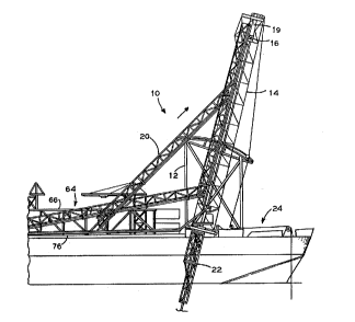
Referring to;Fig. 1, it is seen that the invention is -
generally indicated by the numeral 10. Apparatus 10 for near ~ ~'
vertical laying of pipeJine is generally comprised of su~o~
frame 12, movable deck 13, tower 14, travel block 16, pedestal
18 seen in Fig. 5 and 6, internal pipe clamp 19 seen in Fig. 9,
s~lv~Jl~c~ 20, and stinger 22.
~ '' '.'~
.
",~ ; ",
2132923
CA~E 5390
--6--
Support frame 12 is of any suitable shape and rigidly
attached to the lay vessel 24. In the preferred ~ nt,
support frame 12 is adapted to pivotally receive movable deck 13
and tower 14 such that they may be moved between a first
operative pipe laying position that includes several different
angles as seen in Fig. 1 and a second stowed position for safety
purposes-during rough seas or travel of the lay vessel. To
achieve this, movable deck 13 is pivotally attached at one side
of its lower end to ~ u~pur~ frame 12 and can be rigidly attached
at the opposing side of the lower end to ~u~o ~ frame 12 as seen
in Fig. 12. A variety of attA~' -nt points are provided so that
deck 13 and tower 14 can be set at the desired angle. A winch
and cables are used to raise and lower tower 14.
As seen in the detail view of Fig. 12, tower 14 is mounted
on movable deck 13. Work deck 15 may be pivotally attached to
tower 14 or deck 13 so as to be adjustable to a horizontal
position for perso~nel. Tower 14, seen in Fig. 2, is a U-shA~e~ ~-
frame open on one side along its length and is designed to
su~u~ the weight of the pipeline during the lowering or raising
of the p;pe~ne and to receive and guide the s~ Ac~ into
position in the tower so that a pipe joint may be added to the
pipeline. Travel block 16 is received in tower 14 and au~O ~ed
¦~ by a cable sheave assembly 26 mounted on top of tower 14.
Pedestal 18, seen in Fig. 5 and 6, is mounted on an adjustable
work deck 38 at the lower end of tower 14. Internal pipe clamp
19 is movably positioned adjacent the top of tower 14. Means for
guiding s~on~ack 20 into and out of tower 14 is provided in the
:~:
:;~
~" ;
, ,; ~
~, ~.''::",.'-. ~ ' ~ ''' :
~, ~':"'''"' '- ~' ~, ~ . ''' ,' ~ ,
2132923
.
CAB~ 5390
form of a pair of rails 28 on opposing sides of the tower that
receive rollers on the s~,o~ hAr~. A pair of transition rails
30 extend from the lower end of tower 14 at an angle to aid in
the transition period when the strongback is moving between a
position h~rizontal to the deck of the lay vessel and into or out
of tower 14. A rail switch 32 is used at the junction of rail
28 and transition rail 30 to allow downward movement of
s~runyback 20 in tower 14 once a pipe joint has been bLouyll~ into
tower 14 by strongback 20. A pair of hydraulic cylinders 34
attached to the lower end of tower 14 are positioned to receive
and support strongback 20 during certain phases of the operation.
Sheave 36 on the top of tower 14 provides a ~U~OL~ point for a
cable that is attached to one end of s~,Gr~back 20 and is used
in conjunction with a winch to raise and lower ~L,onyLack 20 into
and out of tower 14.
. . ~ . ~ .,
5~ J~AC~ 20, seen in Fig. 3 and 4, is formed from a
triangular shaped frame and is provided with a plurality of -
clamps 40 spaced along its length. Each end of stro~ghAc~ 20 is
provided with rollers 42 that are sized to be received in rails
28 and 30 on tower 14. In its operational position, the flat
portion of the triangle of ~L~""J~aC~ 20 faces the deck of the
lay vessel on tower 14 and clamps 40 extend from the flat portion
for gripping a pipe joint 44. Clamps 40 are adjustable so as to
be capable of moving between a first retracted position and a
secoo~ extended position to allow alignment of the pipe joint 44
with the pipe]~ne for welding.
Stinger 22, seen in Fig. 1 and 10, is attached to the bottom
''
, .~
2132923
CA8~ 5390
-8-
of the movable work deck 13 (Fig. 12) and designed to provide
support to the pipeline as it is lowered during forward v~ -nt
of the lay vessel. Stinger 22 is formed from two sections that
are pivotally attached to each other. The lower section is
movable between a first retracted or folded position and a secon~
extended position relative to the upper section and the work
deck. In the first position, the lower section is positioned
substantially parallel to the hull of the lay vessel to present
little or no resistance to -~ -nt of the vessel when pipe ;';
laying operations are not underway. This also prevents damage
to the stinger. In the preferred embo~; -nt, stinger 22 is
provided with three clamps 46 that can be used to ':U~UL L the
pipeline during welding of a new pipe joint onto the pipeline.
Stinger 22 matches the angle of tower 14 during pipe laying
operations.
Travel block 16, seen in Fig. 7 and 8, is adapted to ~u~OrL
the weight of a pipe joint or the pipel;ne. As seen in Fig. 7,
travel block 16 is formed from two sections each having a cutout
that defines an op~ning 48 with a diametar sized to receive a
section of pipe when the two travel block sections are adjacent
each other. The two sections of travel block 16 are movable
between a first closed position adjacent each other and a seCon~
open position. The diameter of op~ni ng 48 is smaller than the
diameter of buckle arresters 50, seen in elevation in Fig. 8,
that are attached to the pipe at predetermined intervals.
opPninq 48 is ch~reA to define four rectangular extensions
equally sp~ce~ apart in an otherwise circular op~ninq. The
," , . .
2~32~23
.
CA8B 5390
significance of the shape of opening 48 will be explained below.
It can be ~een that when in the first closed position, travel
block 16 will not allow passage of buckle arrester 50 attached
to a pipe 44 and travel block 16 can be used to support a pipe
joint during welding of a pipe joint onto the pipel;ne or during
lowering of the pipeline by lowering of travel block 16 in tower
14. In the seco~ open position, opening 48 is large enough to
allow passage of buckle arrester 50. ~-
Pedestal 18, seen in Fig. 5 and 6, is similar to travel ;~
block 16 in that it is formed from two sections that are designed
to be movable between a first closed position and a second open -~
position. When in the first closed position, the two sections
define a circular opening 52 sized to receive the pipe being used -~
to lay the pipeline. Base 54 i8 provided with four vertically
ext~nA;ng blocks 56 sp~ce~ equally around the circumference of
: op~ing 52 that are sized to be of lesser diameter than buckle
aLLes~ar 50 when pedestal 18 is in its first closed position. ~ -
Blocks 56 are positioned so as to be in alignment with the four
rectangular extensions in op~n;ng 48 in travel block 16. This
A~lC ~ for a direct transfer of the weight of a pipe joint or the
pipelin~ via buckle arrester 50 from travel block 16 to pedestal
18 as travel block 16 is used to lower the p;pelinD. Blocks 56
~ da through the rectangular extensions in opening 48 as
;~ travel block 16 is lowered and engage buckle arrester 50 to
provide an automatic weight transfer to pedestal 18. Travel
block 16 i8 then moved to its secQn~ open position to clear the
' bnr~le arrester and may then be moved back up to the top of tower ~-
':
~"
2132~23
. :
CA8E 5390
--10--
14 in preparation for the next pipe joint to be added to the
pipeline. Base 54 is supported by two separate plates 57 that
are movable relative to each other. As seen in Fig. 12, pedestal
18 is supported by movable deck 13 and aligned with a hole
provided therethrough. '
Internal pipe cla~p 19, seen in phantom view in Fig. 9, is
retained inside a housing 58 that serves as a means for aligning
and inserting clamp l9 with and into a pipe joint 44 that is
being held in tower 14 by ~L onJb~ck 20. Alignment means is
necess~ry for the following reasons. The pipe laying operations
are conducted in a near vertical position. As a result, it would
be extremely difficult or impossible to lower clamp 19, hanging
by a cable in a normal vertical position, into a pipe that is not
in a vertical position due to the position of tower 14 and
~Lol,yback 20. Housing 58 is sized to be received over the end
of the pipe so that clamp 19 is easily lowered into the pipe for
weldin~ operations. Means for positioning housing S8 over the
pipe i8 provided in the form of hydraulic cylinders 60 that are
attached to tower 14 and adapted via arms 62 to cause the desired
movement of housing 58 between a first retracted position and a
secQn~ extended position in alignment with the pipe joint.
Fig. 11 is an end view of pipe bins 64 that provide for the
storage, trans~GL~, and transfer be~en vessels of pipe joints
to be used in a pipe laying operation. Prior art containers were
l~n~h~e to store a large quantity of pipe without crushing the
pipe at the bottom of the container and did not provide a safe
way of transferring large quantities of pipe from one vessel to
;::
2132323
:'
C:A~E: 53 9 0
--11--
another. Pipe bins 64 solve these problems. A rectangular U~
shaped frame 66 seen in Fig. 1 is divided into upper and lower
storage sections and is provided with a plurality of vertically
exten~i"g horizontal spacers 70. Horizontal ~u~po~s 68 are
removably received in and supported by rectangular frame 66.
Each support 68 is also provided with a plurality of vertically
exten~ing horizontal spacers 70 that are spaced apart according
to the size pipe to be used in the pipe laying operation. As
seen in the end view of Fig. 11, horizontal supports 68 are
provided with a flange 72 on each end that is received in frame
66 to place the load of ~pvr~ 68 and-the pipe loaded thereon
on rectangular frame 66 instead of the pipe in the lower section
of frame 66. Horizontal spacers 70 are provided at suitable
intervals along the length of ~up~v ~s 68 and the bottom of frame
66. Horizontal spacers 70 ~ evènl the pipe from rolling in the
bin during rough seas and pLesen~ing a safety hazard or damaging
the pipe. Any suitable SU~PVL ~ing material such as lu~ber may
be used be~ee,. layers of pipe to evenly spread the load and
evell~ direct pipe contact that could damage the ends of the
pipe. Padeyes or lifting bales 74 are provided on frame 66 to
allow transfer of pipe bin 64 and all pipe stored therein in a
single operation.
In o~e~aLion, a single pipe joint 44 has the ends prepared
for ~ ld~ng to the pipel~n~ and is transferred to a pipe ready
rack 76. As seen in the end view of Fig. 11, ~ol.. J~.~rk 20 is
lowered over ready rack 76 and clamps 40 are used to grasp pipe
joint 44. As seen in the sequence of Fig. 1, s~lGnJ~ck 20 is
:
~:
~ ~ .~
l ~ ~
2132323
CA~ 5390
-12-
then pulled up and guided into tower 14 on rails 30 and 32. The ~-
tower may be set from zero degrees to a fifteen degree angle from
vertical in the preferred ~ ho~; ?~t for laying of pipe in deep
water. Clamps 40 on the strongback are used to move the pipe
joint into alignment with the pipeline. Rail switch 32 is moved
to allow the strongback to move down in tower 14 and onto
strongback lowering cylinders 34. The strongback is lowered by
cylinders 34 until the end of the pipe joint is the proper
distance from the end of the pipeline. Housing 58 is moved into
alignment with the top of the pipe joint, internal pipe clamp 19
is lowered into the pipe joint to the proper position at the
junction of the pipe joint and pipeline, and pipe clamp 19 is
actuated to clamp the ends of the pipe joint and pipeline in the
proper position for welding. Travel block 16 is positioned below
the upper end of the pipe joint and closed around the buckle
arrester on the pipe joint. In the preferred embodiment,
~Lol~J~r~ 20 and clamps 40 are used to ~u~po~ the pipe joint
during the first three weld passes. Clamps 40 are then released
from the pipe joint and retracted to allow ~-v~ ack 20 to be
moved out of tower 14 to pick up another pipe joint from ready
rack 76. During this time, travel block 16, pedestal 18, and
clamps 46 on stinger 22 are used to support the weight of the
pipe joi~t and pipel;ne during the final welding, ~ ;n~tion,
and coating process. After the process is completed, clamps 46
on the stinger are opened and travel block 16 is lowered in tower
14 while the lay vessel 24 moves forward. Vertically exten~;n~
blocks 56 on pedestal 18 p~G~ude through the rectangular cut
~ 2132923
CA8B 5390
--13--
outs in travel block 16 and receive the weight of the pipeline.
Travel block 16 is then opened and raised in tower 14 and ~-
strongback 20 is used to position the next pipe joint in
alignment for welding to the pipeline and the process is
repeated. The ability to transfer the load to the pedestal, free
the travel block to move back into position, and have the next
pipe joint ready for alignment and welding to the pipeline helps
to minimize time required to add pipe joints to the pipeline. ~ ~
Because many varying and differing ho~; -nts may be made ~ ---
within the scope of the inventive concepL herein taught and
because many modifications may be made in the embodiment herein
detailed in accordance with the descriptive requirement of the
law, it is to be understood that the details herein are to be
interpreted as illustrative and not in a limiting sense.
: