Note: Descriptions are shown in the official language in which they were submitted.
2132992
STRIPPABLE COATING FOR OPTICAL FIBER
Technical Field
This invention relates generally to a protective coating for an optical
fiber, and more particularly to a coating which can be easily removed from the optical
fiber.
Back~r~nd of the Invention
In the manufacture of optical fiber, a glass preform rod is suspended
vertically and moved into a furnace at a controlled rate. The plero~ softens in the
furnace and a glass fiber (also referred to as an optical fiber) is drawn freely from the
molten end of the preform rod by a capstan located at the base of a draw tower.
o Because the surface of the glass fiber is susceptible to damage caused by abrasion, it
is necessary to coat the fiber after it is drawn but before it comes into contact with any
surface. Inasmuch as the application of a coating material must not damage the glass
surface, the coating material is applied in a liquid state. Once applied, the coating
material must solidify before the glass fiber reaches the capstan. This is typically
accomplished within a brief time interval by photocuring -- a process in which the
liquid coating material is converted to a solid by exposure to electromagnetic
radiation.
Because the fibers are thin and flexible, they are readily bent when
subjected to mechanical stresses such as those encountered during h~nt11ing or
exposure to varying temperature environments. Such bends in the fiber frequentlyresult in loss that is much greater than the intrinsic loss of the fiber itself, and it has
been found desirable to protect the glass fiber against such bending. Accordingly, the
coating material is required to cushion the glass fiber against bends and two layers of
coating materials are typically applied to the drawn optical fiber. An inner (primary)
coating, having a relatively low modulus, is applied directly to the glass fiber; and an
outer (secondary) coating, having a relatively high modulus, surrounds the primary
coating. Together, these coatings desirably protect the inherently high tensile strength
of the glass fiber so long as the primar.,v coating material remains bonded to the glass.
However, in what appears to be a contradictory requirement, it is also desirable to be
able to easily strip the coating(s) from the glass fiber -- particularly when a number of
fibers are bonded together in an array such as shown in U. S. Patent 4,900,126 which
leads to yet another performance attribute that coating materials need to possess.
Indeed, if the coating materials cannot be cleanly and easily stripped, then splicing
and connectorizing operations will be seriously hampered.
U. S. patent 4,472,021 discloses a strippable coating for an optical
fiber which comprises from about 2% to about 20% of an organic polysiloxane
2 2132992
additive having a plurality of hydroxy-termin~tçd groups which are joined to some of
the silicon atoms in the polysiloxane chain by a carbon-to-silicon bond. This
particular additive, however, exhibits low adhesion to the glass fiber which adversely
affects the handling propcillies of the coated optical fiber during the manufacturing
process. Low adhesion is a problem which, in the worst case, leads to "del~min~tion"
and the ensuing incursion of water, particularly upon exposure to high humidity,which attacks the glass surface and reduces tensile strength.
What is needed, and seemingly what is not disclosed in the prior art, is
an additive for use in a coating for optical fibers which improves st~ippability while
still m~int~ining a&esion to the glass fiber.
Summa~ of the Invention
An optical fiber comprises a glass portion for guiding lightwaves
which is covered by one or more layers of a coating material to protect the glass from
abrasion. The coating material is improved by adding 1-20% by weight of a non-
crosslinked hydrocarbon component to a formulation comprising: an oligomer (50-
80% by weight); a diluent (less than 50% by weight); and other additives (5-35% by
weight). The improved coating material is easily removed from the glass portion
while m~ g good adhesion thereto during normal use and h~n~11in~.
In a plefelled embodiment of the invention, the oligomer has an
overall structure C-B-A-B-C in which "A" represents a polyol, "B" represents
diisocyanate, and "C" represents hydroxy-termin~ted alkyl acrylate. The hydrocarbon
component has the structure Rl - (R)n - R2; where Rl, R2 comprises an aL~yl group or
an OH group, and R is a combination of C, H or C, H, O.
In an alternate embodiment of the invention, the need for a diluent is
substantially elimin~ted by using an oligomer having the structure E-D-E where "D"
represents a carboxy-tennin~te~l polyol, and "E" represents a glycidyl acrylate.Brief Description of the D. ~. in~
The invention and its mode of operation will be more clearly
understood from the following detailed description when read with the appended
drawing in which:
FIG. 1 is an end view, in cross section, of an optical fiber which
includes a coating system;
FIG. 2 is a perspective view of an optical fiber ribbon showing a group
of coated glass fibers bonded together with a matrix material;
FIG. 3A-3C illustrate the use of a ribbon-stripping tool showing three
progressive stages in the removal of matlix and coating materials from a group of
glass fibers;
FIG. 4A-4C illustrate various outcomes of the ribbon-stripping
3 213~992
-
procedure; and
FIG. 5 is a graph which illustrates the effect of aging on pullout
force for dual-coated fiber.
Detailed Description
FIG. 1 shows an end view, in cross section, of a coated optical fiber 10
comprising a glass fiber 12 surrounded by a protective coating system comprisinglayers 14, 15. It is well known to draw glassy optical fiber from a specially prepared,
cylindrical preform which has been locally and symmetrically heated to a temperature
of about 2000~C. As the preform is fed into and through a furnace, glass fiber 12 is
0 drawn from the molten material. A protective coating system is applied to the glass
fiber 12 after it has been drawn from the preform which preferably comprises twolayers of radiation-cured polymeric m~teri~l~. An inner layer 14 contacts the glass
fiber 12 at a glass-coating interface 13 and is referred to as a primary coating material.
An outer layer 15, which is referred to as a secondary coating material, surrounds the
inner layer. One method of applying dual layers of coating materials to a movingglass fiber is disclosed in U.S. Patent 4,474,830 which issued on Oct. 2, 1984 to C. R.
Taylor. Another method for applying dual layers of coating materials onto glass fiber
is disclosed in U.S. Patent 4,851,165 which issued on July 25, 1989 to J. A. Rennell
and C. R. Taylor. By way of illustration, the typical diameter of glass fiber 12 is
about 125 micrometers, while the diameter of its core 11 is generally less than 10
micrometers for single mode fibers. (Core 11 is the region where light is substantially
confined during its propagation along the glass fiber's longitudinal axis by therefractive index profile of the glass fiber.) And finally, each layer of coating material
has a thickness of about 30 micrometers so that the overall diameter of coated fiber 10
is approximately 250 rnicrometers.
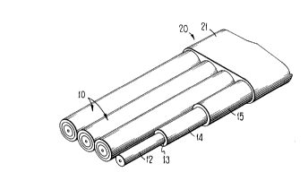
Referring now to FIG. 2, there is shown a perspective view of an
optical fiber ribbon 20 showing a group of coated glass fibers 10-10 that are held
together with an ultraviolet (UV)-curable matrix bonding material 21. The group of
optical fibers are disposed in a coplanar parallel array, and while only four (4) fibers
are shown, such arrays typically comprise twelve (12) individual fibers. The modulus
of the matrix material has a value less than that of the outer coating layer of the fiber
but greater than the modulus of the inner coating layer. The matrix material 21 fills
the interstices, bonds together the optical fibers, and extends to the outside boundary
of the ribbon. A typical UV-curable matrix material 21 is a mixture comprising aresin, a diluent and a photoinitiator. The resin may include a diethylenic-termin~ted
resin svnthesized from a reaction of a hydroxy-termin~te~l alkyl acrylate with the
reaction product of a polyester of polyether polyol of molecular weight of 1000 to
6000 Dalton with an aliphatic or aromatic diisoctyanate, or a diethylenic-termin~ted
-4-- ~32992
resin synthesized from the reaction of glycidyl acrylate with a carboxylic-tennin~ted
polymer or polyether of molecular weight 1000 to 6000 Dalton. The diluent may
comprise monofunctional or multifunctional acrylic acid esters having a molecular
weight of 100 to 1000 Dalton or N-vinylpyrrolidinone. For the photoinitiator, the
s composition may include ketonic compounds such as diethoxyacetophenone,
acetophenone, benzophenone, benzoin, anthraquinone, and benzil dimethyl ketal. In a
typical composition, the bonding matrix may include a resin (50-90%), diluents (5-
40%), and a photoinitiator (1-10%). All percentages are by weight unless otherwise
noted. Other bonding matrices may include a methacrylate, a UV-curing epoxide oran unsaturated polyester. More detailed information regarding bonded arrays of
optical fibers is available in the aforementioned U.S. Patent 4,900,126.
Bonded arrays of optical fibers, as discussed above, are commercially
available from AT&T under the tr~dçm~rk of AccuRibbon~) lightguide cable, and isespecially useful for high fiber count installations in the loop and metropolitan area
networks where splicing and in~t~ tion productivity are paramount. Each ribbon
comprises 12 color-coded fibers for easy identification, and as many as 12 ribbons are
stacked together for high density. The ribbon stack is surrounded by a core tubewhich may also contain a filler that prevents the incursion of water in outside plant
applications.
Ribbon Slri~irlg
Reference is made to FIG. 3A-3C which illustrate the use of a ribbon-
stripping tool such as used by splicing technicians for mass fusion splicing. FIG. 3A
shows the principal elements of the ribbon stripping tool and associated appalalus.
Ribbon 20 is placed within fiber holder 30 to facilitate h~nclling of the fiber during the
2s stripping process. The stripping tool comprises holder grip 40 and main body 50
which are used for removing the various layers that surround a bonded fiber array.
Lid 53 is closed during the stripping operation and includes an inner surface 54 which
cooperates with a heated platen 51 to frictionally hold the outside jacket material
surrounding the glass fibers within ribbon 20.
Referring first to F~G. 3A, fiber holder 30 is shown in its closed
position around ribbon 20 which about to be inserted into the ribbon-stripping tool.
The portion of ribbon 20 which is to have its coating layers removed extends beyond
the forward end of the fiber holder so that it can be captured between platen 51 and
the inside surface 54 of lid 53 when the lid is closed onto the main body 50. Upon
3s closure, opposing blades 55, 56 are positioned to cut partially into opposite sides
ribbon 20 so that a well-defined break in the coating material can be made. The
particular tool used is electrically heated from an AC power source which is converted
to 12 volts DC for use by a heater element within the main body 50. Holder grip 40 is
~ 5 - 21 3~92
adapted to capture fiber holder 30 therein when its lid 43 is closed.
FIG. 3B illustrates the movement of holder grip 40 away from the main
body 50 of the ribbon-stripping tool. Guide rails 45-45 allow the holder grip to slide
into engagement with the main body in a controlled manner. A heater (not shown)
within the main body raises the temperature of platen 51 to a predetermined level
which weakens/breaks the adhesive bond at the interface 13 between primary coating
14 and glass fiber 12 (see FIG. 1 or 2) of the various coated fibers. Illustratively, a
temperature of 100~C for about 2 minutes provides acceptable results. Once the bond
is weakened/broken the rest of the operation involves sliding the primary coating
lo along the glass fiber surface. The ability of the primary coating to slide will depend
on it sliding friction with the glass fiber. This action will determine how easily the
composite (matrix 21 and coatings 14, 15) can be removed and the amount of residue
that remains on the bare glass fibers. Therefore, a non-crosslinking and non-reactive
additive is incorporated into the primary coating formulation which remains mobile
(i.e., free to diffuse) in the primary coating after cure so that when the stripping
operation is pclrolllled the additive will be present at the surface of glass fiber 12 to
thereby reduce sliding friction.
Finally, FIG. 3C shows end results of the ribbon stripping process in
which glass fibers 12-12 protrude from ribbon 20 which is still held within the fiber
holder 30. And matrix material 21 which has just been stripped away remains on the
heated platen 51 of the main body 50. Having stripped the matrix and coating
materials away from the glass fibers 12-12, FIG. 4A-4C are used for illustrating the
various possible results of the stripping process and for discussing their acceptability.
For example, FIG. 4A shows an ideal condition wherein the matrix 21 and coating
materials 14, 15 are fully removed from the glass fibers 12-12. Such results arefrequently possible with the present invention although the presence of some residues
16-16, as shown in FIG. 4B, is also acceptable provided they can be removed by
gentle wiping with an alcohol-moistened cotton swab. However, FIG. 4C illustrates
an unacceptable condition in which the coating materials have clung to the glass fibers
so tenaciously that either breakage occurs or large patches remain that cannot be
easily removed.
Coating Materials
Coating materials not only protect the glass fiber from abrasion and
cushion it against microbending loss, but they also help preserve its tensile strength.
However, in order to preserve tensile strength, the coating materials must stay bonded
to the glass -- at least until they are stripped off, and then it is desirable that they be
fully removable without leaving a residue on the glass. More specifically, the
-6- 2132~92
interface between the primary coating material and the glass fiber must be
characterized by suitable strength to prevent del~min~tion, and must be such that the
coating system can be stripped from the optical fiber without tenacious residues being
left on the fiber surface. On the other hand, the surface of the secondary coating
5 material must be such that tacking does not occur between adjacent convolutions of
the fiber, resulting in a jerky payoff from a process spool.
Typical coating materials comprise urethane acrylate liquids whose
molecules become crosslinked when exposed to ultraviolet light. Various additives
are also present that enhance one or more properties of the coating. For example,
lo photoinitiators are added to accelerate the curing process which is important because
coated optical fiber is wrapped around spools for storage as soon as it is cured, and
manufacturing speed is critical to profitability.
Curing is the conversion of the liquid coating material to a solid. In the
present system this process is known as free radical cure wherein, upon absorption of
1S light, the photoinitiator components cleave to form free radical pairs which diffuse
away from each other and react with acrylate-terrnin~tecl components to initiate a
chain polymerization process. In addition to photoinitiators, coating materials further
include diluents, antioxidants, adhesion promoters and, in some cases, additives to
improve strippability. However, before addressing strippability, it is important to first
20 discuss the composition of the primary coating material which makes contact with the
glass surface, and whose properties are the subject of the present invention.
In the prer~-led embodiment of the invention, primary coating 14
comprises a 30 micron-thick layer of a material that surrounds glass fiber 12. It has a
low modulus (e.g., 106 Pa) to cushion the glass fiber against sharp bends that cause
25 loss to a lightwave signal. The primary coating illustratively comprises an oligomer
(50-80%), a diluent (15-40%), and additives (5-35%). The oligomer is derived from
polyol ("A") which has been reacted with diisocyanate ("B"), and capped with
hydroxy-termin~te~ alkyl acrylate ("C"). The resulting structure is of the form C-B-
A-B-C where:
"A" ~ (R1) - (R)n - (R2);
where: Rl, R2 is an OH group;
R is a combination of C, H or C, H, O;
and2<n<1000
B" ~ O=C=N-(R3~-N=C=)
where: R3 is an alkyl or aromatic group
~ _ 2l 3299~
o
"C"~ HO - (R4) - O - C - CH = CH2
where: R4 is an alkyl group with 2-6 carbon atoms;
Illustratively, phenoxyethylacrylate is a suitable diluent for use
in the optical fiber coating of the present invention which serves to decrease the
viscosity of the oligomer resin. However, decreased viscosity can also be achieved
through use of an epoxy acrylate oligomer having the general structure E-D-E, inwhich case the amount of diluent used can be reduced to less than 15%. In this
situation, a carboxy-tennin~ted polyol, design~ted "D", comprises the following
0 structure:
O O
Il 11
" D"~ OH - C - (R)n -C - OH
where: R is a combination of C, H or C, H, O;
and 2 S n < 1000
and a glycidyl acrylate, desi~n~tecl "E," comprises the following structure:
O O
"E"~ C - C - (Rs) - OC CH2 CH2
where: (Rs) is an alkyl group
Various polyols (alcohols containing plural hydroxyl groups) may be used in the
oligomer chain including:
(i) polycarbonate;
(ii) polyester;
(iii) polyether;
(iv) polybutadiene; or
(v) hydrogenated polybutadiene.
Additives
Selection of the proper additive to facilitate removal of the primary
coating from a glass fiber without severely limiting its adhesion thereto is a non-trivial
problem, particularly because both properties are required and appear to be mutually
exclusive. However, as with so many such problems, cOlllplolllises are possible
because there exists a region where both removability and adhesion are acceptable.
This is to say that the adhesive force need not be much greater than the highest force
-8- 21329~2
_
expected during handling; nor should it be much less than the lowest force expected
when the coating is being intentionally stripped from the fiber. And whereas the prior
art discloses the addition of polysiloxane to enhance strippability, it has beendiscovered, much to our surprise, that the addition of hydrocarbon components to the
5 coating material, in an amount from about 1-20%, appear to cover the above-
mentioned region. For example, maximum acceptable adhesion is provided when
only 1% of the hydrocarbon component is added, and minimum acceptable adhesion
is provided when 20% of the hydrocarbon component is added. The use of
hydrocarbon components to achieve these desired results is surprising because
lo formulators historically have avoided the use of non-crosslink~ble components due to
anticipated and/or obseNed detrimental properties in the cured form. Additives
blended into the coating material either
bind to the coating material, bind to the glass after the coating material is applied, or
are free to migrate. The latter type are sometimes called fugitive because they do not
15 form crosslinks. Unfortunately, many of the fugitive additives cause loss of adhesion
or increased surface tack.
Among the additives, an antioxidant is present in an illustrative
amount of about 0.5%, an adhesion promoter is present in an illustrative amount of
0.5-2.0%, and a photoinitiator is present in an illustrative amount of about 2%. Most
20 importantly, hydrocarbon component additives have been found to provide
surprisingly beneficial effects on ribbon strippability, with an app1~p1iate degree of
adhesion, when they are present in an amount 1-20%.
In a preferred embodiment of the invention, polytetrahydrofurandiol (a
polyether), having the following structure, is used in forming the oligomer:
HO - (O CH2 CH2 CH2 CH2 )n ~ OH
Further, in the ~1cf~11ed embodiment of the invention, polytetrahydrofurandiol is used
as the hydrocarbon component. Indeed, although not required in the present
30 invention, the preferred hydrocarbon component additive comprises the same polyol
used in forming the oligomer.
Reference is now made to FIG. 5 which is a graph that illustrates the
effect of aging on pullout force for a dual-coated fiber. In particular, the region which
is designated as being "ACCEPTABLE" defines the amount of force needed to
35 remove the coating from a dual-coated fiber without problem. When adhesion
between the coating material and the glass fiber becomes too great, as indicated by
curve I, it is most difficult to remove the coating from the glass fiber withoutbreakage. Frequently, the fiber does not break, and yet some coating material remains
9 21 329~92
-
attached to the glass after a portion has been removed (see e.g., FIG. 4C). Whenadhesion between the coating material and the glass fiber becomes too little, asindicated by curve III, the above-described problem of del~tnin~tion occurs which
may lead to the incursion of water and consequent weakening of the glass fiber'ss tensile strength. Finally, curve II illustrates the beneficial result of adding hydrocarbon
components in an amount 1-20% to the coating material. In this situation, the
stripping force of the coating material is sufficiently low so that tenacious residues do
not remain on the glass fiber, yet sufficiently high that del~min~tion is not a problem.
The ACCEPTABLE region is quanlitali~/ely shown in FIG. 5 based on measurements
0 of the ~llip~ g force required to remove coating materials from a dual-coated fiber as
a function of time for various coating materials.
It has been observed that migration of the added hydrocarbon
components is such that they may also be used in the secondary coating, albeit with
reduced effectiveness. And while various embodiments of the invention have been
15 shown and described, it is recognized that modifications may be made by those of
ordinary skill which are within the spirit and scope of the present invention.