Note: Descriptions are shown in the official language in which they were submitted.
- 2133050
DOOR LOCK HAVING A DEADBOLT ASSEMBLY WITH
A LOW-COST CORROSION-RESISTANT BOLT MEMBER
FIELD OF THE INVENTION
The invention relates to a door lock, more
5particularly to a door lock which cannot be
disassembled from the outer side of a door, which is
easy to install and which has a deadbolt assembly with
a low-cost, corrosion-resistant bolt member.
BRIEF DESCRIPTION OF THE DRAWINGS
10In drawings which illustrate an embodiment of the
invention,
Figure 1 is an exploded view of a conventional door
lock disclosed in U.S. Pat. No. 3,992,908;
Figure 2 is an exploded view of a conventional
15deadbolt assembly disclosed in U.S. Pat. No. 4,664,433;
Figure 3 is a sectional view illustrating the
operation of the conventional deadbolt assembly shown
in Figure 2;
Figure 4 is a partly exploded view of the preferred
20embodiment of a door lock according to the present
invention;
Figure 5 is a perspective view illustrating an
exterior housing section and an interior sleeve member
of the preferred embodiment;
25Figure 6 is a partly exploded view of a deadbolt
assembly of the preferred embodiment;
21330~
Figure 7 is a partly sectional view of the deadbolt
assembly with a bolt member thereof being shown in a
fully extended position;
Figure 8 is a partly sectional view of the deadbolt
assembly with the bolt member thereof being shown in a
fully retracted position;
Figure 9 illustrates an exploded view of the bolt
member of the preferred embodiment;
Figure 10 is a sectional view of the bolt member
when assembled to a pull member at a longer backset
length; and
Figure 11 is a sectional view of the bolt member
when assembled to the pull member at a shorter backset
length.
BACKGROUND OF THE INVENTION
Figure 1 illustrates a door lock disclosed in U.S.
Pat. No. 3,992,908. The door lock is shown to comprise
a lock housing assembly (A) and a deadbolt assembly
(B). The lock housing assembly (A) is to be installed
in a through bore of a door (not shown), while the
deadbolt assembly (B) is to be installed in an opening
that is at right angles with the through bore of the
door.
The lock housing assembly (A) comprises an exterior
housing section (A1) with an interior sleeve extension
(A11) which has a rear end formed with diametrically
opposite notches (A12) that permit the extension of the
`- 21~30~G
deadbolt assembly (B) through the sleeve extension
(A11). The sleeve extension (A11) is formed with an
internal screw thread (A13). The exterior housing
section (A1) has a cylindrical chamber that receives an
exterior lock cylinder unit (A14) therein. The lock
cylinder unit (A14) has a key-operated rotary plug
(A15) with a rearwardly projecting spindle (A16).
An interior housing section (A3) may be coupled
directly to the exterior housing section (A1) by means
of an external screw thread (A31) thereof, or may be
coupled indirectly thereto by means of an internally
and externally threaded coupling sleeve (A2) which
engages the thread (A13) of the sleeve extension (A11)
and which further engages the thread (A31) of the
interior housing section (A3).
The lock housing assembly (A) further comprises an
interior cylindrical insert (A4) adapted to be received
in a bore (A32) of an interior housing section (A3). An
interior lock cylinder unit (A5) is contained within a
chamber of the insert (A4) and has a rotary key-
operated plug (A51) with a spindle (A52) that interfits
telescopically the spindle (A16).
It is noted that, although the arrangement of the
exterior housing section (Al) and the deadbolt assembly
(B) can lock the former against rotation, the
application of a great amount of torque on the exterior
housing section (A1) may result in damage to the door
~133D~3
lock, thus facilitating the disassembly of the door
lock from the outer side of the door.
Figures 2 and 3 illustrate a deadbolt assembly
disclosed in U.S. Pat. No. 4,664,433. The deadbolt
assembly is shown to comprise a deadbolt casing
assembly (C) and a drive arm (D). The casing assembly
(C) includes a spaced pair of side plates (Cl). The
drive arm (D) is disposed between the side plates (C1)
and has a first end formed with a cylindrical hub (Dl).
The cylindrical hub (Dl) has two ends mounted rotatably
and respectively to the side plates (Cl). A pull member
(E) has a rearward extension (El) that extends into the
casing assembly (C) and that is formed with a driving
hole (E2). The pull member (E) is movable forwardly and
rearwardly in the casing assembly (C). The second end
(D2) of the drive arm (D) extends into the driving hole
(E2). Forward and rearward movement of the pull member
(E) occurs when the cylindrical hub (Dl) is rotated by
a spindle (not shown). A leaf spring (G) extends
between the side plates (Cl) below the drive arm (D)
and defines the forward and rearward positions of the
drive arm (D).
The deadbolt assembly further comprises a bolt
member (F) with a forward bolt part (Fl) and a rearward
bolt part (F2). The forward bolt part (F1), which has a
closed front end and an open rear end, further has
opposite flat sides (Fll) and curved upper and lower
2~3~0~0
sides (F12). The rearward bolt part (F2), which has
open front and rear ends, further has a circular cross
section and is telescoped by the forward bolt part
(F1). The rearward bolt part (F2) is formed integrally
with the pull member (E) and telescopes a hardened
security bar (F3) at the front portion thereof to
provide added security against transverse sawing of the
bolt member (F).
The rearward bolt part (F2) has two helical slots
(F21, F22) formed therein. A guide pin (F4) extends
across the flat sides (F11) of the forward bolt part
(F1) and passes through the helical slots (F21, F22).
Relative rotation between the bolt parts (F1, F2), as
guided by the guide pin (F4), would result in an
increase or decrease in the total length of the bolt
member (F) so as to attain a longer or shorter standard
backset length.
In the bolt member (F), the forward bolt part (F1)
is not fitted over the rearward bolt part (F2) to
permit relative rotation therebetween. Thus, even when
the forward bolt part (F1) is made of stainless steel,
the rearward bolt part (F2) is still susceptible to
corrosion when the deadbolt assembly is used in humid
places. Of course, the bolt parts (F1, F2) may both be
made of stainless steel to overcome the above drawback.
However, a corresponding increase in the material cost
of the bolt member (F) will be incurred.
~13:~05~
SUMMARY OF THE INVENTION
Therefore, the objective of the present invention is
to provide a door lock which cannot be disassembled
from the outer side of a door, which is easy to
install and which has a deadbolt assembly with a low-
cost, corrosion-resistant bolt member.
Accordingly, the door lock of the present invention
comprises a deadbolt assembly and a lock housing
assembly.
The deadbolt assembly comprises a pull member, a
bolt member, a deadbolt casing assembly and a drive
arm.
The pull member has a hollow forward extension with
a front end that is formed with a bar receiving hole,
and a rearward extension connected to the forward
extension.
The bolt member includes a metal inner sleeve, a
security bar, and a metal outer sleeve. The inner
sleeve has a front wall with a through-hole formed
therethrough, and an open rear end which is sleeved on
and which is secured to the forward extension of the
pull member. The security bar is made of a high-
strength metal material and has a shank portion which
extends into the inner sleeve via the through-hole in
the front wall of the inner sleeve. The shank portion
has a tip which extends into the bar receiving hole of
the forward extension. The outer sleeve is made of a
``- 2~3305~
material which is different from that of the inner
sleeve and which has anti-corrosion properties. The
outer sleeve has a closed front end and an open rear
end. The inner sleeve is inserted fittingly into the
outer sleeve via the open rear end of the outer sleeve.
The deadbolt casing assembly includes a bolt casing
and a pair of spaced side plates. The bolt casing
receives the bolt member slidably therein and has an
open rear end to permit extension of the forward
extension of the pull member therein. The side plates
are formed with a pair of mounting holes and have front
ends connected to the open rear end of the bolt casing.
The side plates further have inner wall surfaces formed
with a respective boss between the mounting holes. The
rearward extension of the pull member rests slidably on
each boss and is movable forward and rearward relative
to the side plates.
The drive arm is disposed between the side plates
and has a first end which is mounted rotatably to the
boss of each of the side plates and which is formed
with a spindle hole, and a second end which engages
operably the rearward extension of the pull member.
The lock housing assembly includes an exterior
housing section, an interior sleeve member, and an
interior housing section.
The exterior housing section has a cylindrical
chamber that receives rotatably an exterior lock
"'- 21330~0
cylinder unit therein. The lock cylinder unit has a
key-operated rotary plug with a rearwardly projecting
spindle. The lock cylinder unit further has a rear side
formed with a pair of threaded holes.
The interior sleeve member is formed as a
cylindrical wall with a front end which is secured to
the rear side of the lock cylinder unit and a rear end
which is formed with diametrically opposite notches.
The deadbolt assembly extends through the sleeve member
via the notches. The spindle extends through the front
end of the sleeve member and into the sleeve member to
engage the spindle hole of the drive arm.
The interior housing section is formed with a pair
of bolt holes. A pair of bolts pass through the bolt
holes of the interior housing section, the mounting
holes of the side plates, the front end of the sleeve
member, and engage threadedly the threaded holes of the
lock cylinder unit.
DETAILED DESCRIPTION OF THE PREFERRED EMBODIMENT
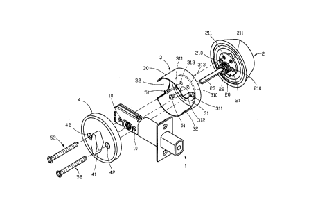
Referring to Figures 4 and 5, the preferred
embodiment of a door lock according to the present
invention is shown to comprise a lock housing assembly
and a deadbolt assembly 1. The lock housing assembly is
to be installed in a through bore of a door (not
shown), while the deadbolt assembly 1 is to be
installed in an opening that is at right angles with
the through bore of the door.
- 2~33050
The lock housing assembly comprises an exterior
housing section 2, an interior sleeve member 3, and an
interior housing section 4. The interior sleeve member
3 is formed as a cylindrical wall 30 with a front end
which is provided with a mounting plate 31 and a rear
end which is formed with diametrically opposite notches
32 that permit the extension of the deadbolt assembly 1
through the sleeve member 3. The mounting plate 31 is
formed with a central depression 310, a pair of
diametrically opposite first through-holes 311, a
second through-hole 312 between the first through-holes
311, and a pair of third through-holes 313 adjacent the
second through-hole 312. The third through-holes 313
permit the extension of two screws 51 therethrough.
The exterior housing section 2 has a cylindrical
chamber that receives rotatably an exterior lock
cylinder unit 20 therein. The lock cylinder unit 20 has
a key-operated rotary plug 22 with a rearwardly
projecting spindle 23. The lock cylinder unit 20 has a
bottom side 21 which extends into the depression 310
and which is formed with a pair of first threaded holes
210 aligned with the first through-holes 311, and a
pair of second threaded holes 211 aligned with the
third through-holes 313. The second through-hole 312 of
the interior sleeve member 3 permits the extension of
the spindle 23 therethrough to enable the latter to
engage operably the deadbolt assembly 1. The screws 51
- X~30~0
engage threadedly the second threaded holes 211 to
secure the sleeve member 3 to the lock cylinder unit
20, as shown in Figure 5.
Due to the presence of the notches 32 in the sleeve
member 3, the first threaded holes 210 of the lock
cylinder unit 20 can be easily aligned with a pair of
mounting holes 10 of the deadbolt assembly 1, thereby
facilitating installation of the door lock of the
present invention.
In this embodiment, the interior housing section 4
is formed with a pair of bolt holes 42 and a rotary
knob 41 for operating the deadbolt assembly 1 from the
inner side of the door in a known manner. A pair of
bolts 52 pass through the bolt holes 42 of the interior
housing section 4, the mounting holes 10 of the
deadbolt assembly 1, the first through-holes 311 of the
sleeve member 3, and engage threadedly the first
threaded holes 210 of the lock cylinder unit 20. This
illustrates how the door lock of the present invention
is secured to a door.
In the present invention, the exterior housing
section 2 is capable of rotating freely relative to the
lock cylinder unit 20. Because the interior sleeve
member 3 is secured to the lock cylinder unit 20
instead of the exterior housing section 2, the door
lock of this invention is not damaged even when a great
amount of torque is applied on the exterior housing
213'~050
section 2.
It is noted that the arrangement of the holes 311,
312 and 313 of the sleeve member 3 should not be
limited to that described beforehand. For example, the
arrangement of the holes 311, 312 and 313 may be
modified, such as by intercommunicating the holes 311,
312, 313, without affecting the purpose of the sleeve
member 3.
Referring to Figures 6 to 8, the deadbolt assembly
is shown to comprise a deadbolt casing assembly 6, a
drive arm 7, a pull member 8 and a bolt member 9. The
casing assembly 6 includes a pair of side plates 61a,
61b, the front ends of which are connected to the open
rear end of a bolt casing 90. The bolt casing 90, which
receives the bolt member 9 slidably therein, has an
open front end with a face plate 91 mounted thereto.
The face plate 91 is to be connected to a vertical edge
of a door in a known manner. The rear end of one of the
side plates 61a is provided with a folded extension 62
that is bent toward the other one of the side plates
61b and that is formed with a pair of lugs 621 which
engage a pair of openings 610 formed in the rear end of
the other one of the side plates 61b, thereby
connecting spacedly the side plates 61a, 61b. The side
plates 61a, 61b are formed with the mounting holes 10
which permit the extension of the bolts 52 therethrough
(see Figure 4). In this embodiment, the side plate 61b
2l~3nso
has a top edge formed with an inwardly projecting
flange 64. Each of the side plates 61a,61b further has
an inner wall surface that is formed with a boss 65
between the mounting holes 10. The boss 65 has a top
5surface which is spaced from the top edge of the side
plates 61a, 61b and which, by itself or in cooperation
with the flange 64, provides a guideway 66 for the pull
member 8. The boss 65 is formed with a hub receiving
hole 11.
10The drive arm 7 is disposed between the side plates
61a, 61b and has one end formed with a cylindrical hub
71. The cylindrical hub 71 has two ends which extend
rotatably into the receiving hole 11 of the respective
side plate 61a, 61b. The cylindrical hub 71 is formed
15with a spindle hole 72 which permits the extension of
the spindle 23 therethrough (see Figure 4).
The pull member 8 has a forward extension 82 that
extends into the bolt casing 90 and that is connected
to the bolt member 9 (see Figure 9), and a rearward
20extension 81 that extends between the side plates 61a,
61b and that is formed with a driving hole 80. The
rearward extension 81 extends slidably into the
guideways 66 of the side plates 61a, 61b. That is, the
rearward extension 81 rests slidably on the bosses 65
25to ensure proper forward and rearward movement of the
rearward extension 81 relative to the side plates 61a,
61b. The other end 73 of the drive arm 7 extends into
'~133050
the driving hole 72. Forward and rearward movement of
the pull member 8 occurs when the cylindrical hub 71 is
rotated by the spindle 23.
A leaf spring 75 is formed as a resilient strip with
a front support portion 751 and a rear hook portion
752. The leaf spring 75 extends between the side plates
61a, 61b below the drive arm 7. The front support
portion 751 of the leaf spring 75 rests on a transverse
support beam 63 of one of the side plates 61a, while
the rear hook portion 752 engages a slit 620 in the
folded extension 62. The hub 71 rests on an
intermediate portion of the leaf spring 75. The leaf
spring 75 serves to define the forward and rearward
positions of the drive arm 7 to define correspondingly
extended and retracted positions of the bolt member 9,
as shown in Figures 7 and 8.
The flange 64 of the side plate 61b cooperates with
the other side plate 61a to define a guide slot
therebetween. The top edge of the side plate 61a is
further formed with a stop flange 67 that extends
toward the other side plate 61b and that is disposed
adjacent to the front ends of the side plates 61a, 61b.
The driving hole 80 of the pull member 8 is a
rectangular hole with two longitudinal edges, one of
which is formed with an upwardly projecting limit
flange 801 that extends into the guide slot. The limit
flange 801 and the stop flange 67 cooperate to prevent
21~305~
removal of the pull member 8 and the bolt member 9 via
the open front end of the bolt casing 90.
Referring to Figures 9 to 11, the bolt member 9 is
shown to comprise a metal outer sleeve 92, a metal
inner sleeve 93 and a security bar 94.
The outer sleeve 92 is made of a metal material with
anti-corrosion properties, such as stainless steel, and
is made from a metal sheet through conventional sheet
forming techniques. The outer sleeve 92, which has a
closed front end 921 and an open rear end 922, further
has opposite flat sides and curved upper and lower
sides.
The inner sleeve 93 is made of a metal material
which is different from that of the outer sleeve 92,
such as zinc alloy or copper, and is similarly made
from a metal sheet through known sheet forming
techniques. The inner sleeve 93 further has a cross
section similar to that of the outer sleeve 92 and is
inserted fittingly in the latter via the open rear end
922 of the outer sleeve 92. The inner sleeve 93 has a
front wall 931 that is formed with a circular recess
932 and a through-hole 9 33 at an innermost end of the
circular recess 932. The inner sleeve 93 further has an
open rear end 934 which is sleeved on the forward
extension 82 of the pull member 8. The periphery of the
open rear end 934 is formed with a number of inward
positioning ribs 935 and two pin receiving holes 936.
2~330~9
The forward extension 82 of the pull member 8 is
hollow and is generally rectangular in cross section.
The forward extension 82 has an open front end 821 with
a longitudinally extending bar receiving hole. The
sforward extension 82 further has at least one side wall
formed with first and second pin hole sets 822, 823.
The first pin hole set 822 is disposed closer to a
front distal end of the forward extension 82 than the
second pin hole set 823.
10The positioning ribs 93S guide the movement of the
forward extension 82 into the inner sleeve 93 when the
forward extension 82 is inserted into the open rear end
934 of the latter. When inserted, the pin receiving
holes 936 of the inner sleeve 93 are aligned with the
15first pin hole set 822 to obtain a bolt member with a
longer backset length, as shown in Figure 10.
Alternatively, the pin receiving holes 936 of the inner
sleeve 93 may be aligned with the second pin hole set
823 to obtain a bolt member with a shorter backset
20length, as shown in Figure 11. A pair of pins 95 extend
through the pin receiving holes 936 and the selected
one of the first and second pin hole sets 822, 823 to
secure the inner sleeve 93 to the forward extension 82.
The security bar 94 is formed as a cylindrical bar
25and is made of a high-strength metal material, such as
high-carbon steel. The security bar 94 has a head
portion 941 which is received in the circular recess
0 5 0
932 in the front wall 931 of the inner sleeve 93, and a
shank portion 942 which extends into the inner sleeve
93 via the through-hole 933. Preferably, the tip of the
shank portion 942 extends into the bar receiving hole
in the open front end 821 of the forward extension 82
and is retained rotatably thereby so as to provide
added security against transverse sawing of the bolt
member 9.
In this embodiment,the front end 921 of the outer
sleeve 92 is punched so as to form a retaining groove
923 that engages the head portion 941 of the security
bar 94.
After the inner sleeve 93 and the security bar 94
have been assembled into the outer sleeve 92, the
periphery of the open rear end 922 of the outer sleeve
92 is folded to engage the periphery of the open rear
end 934 of the inner sleeve 93, thereby preventing the
disengagement of the inner sleeve 93 from the outer
sleeve 92.
Since the outer sleeve 92, which is made of a metal
material with excellent anti-corrosion properties, is
fitted over the inner sleeve 93, the outer sleeve 92
can provide adequate protection to the inner sleeve 93
against corrosion. Thus, the inner sleeve 93 does not
corrode easily even when it is made of an inexpensive
metal with poor anti-corrosion properties.
16
While the present invention has been described in
connection with what is considered the most practical
and preferred embodiment, it is understood that this
invention is not limited to the disclosed embodiment,
but is intended to cover various arrangements included
within the spirit and scope of the broadest
interpretation so as to encompass all such
modifications and equivalent arrangements.