Note: Descriptions are shown in the official language in which they were submitted.
1- 2133116
APPLICATION FOR PATENT
3 INVENTOR: CARLOS E. GIL, MICHAEL RIES,
and ST~V~N A. GARNER
TITLE: BONE SECTION REATTACHNENT
APPARATUS AND MEI~IOD
SPECIFICATION
BACRGROUND OF THE INVENTION
Field of the Invention
The invention generally relates to an apparatus
and method useful for the reattachment of a bone
section removed during surgery and, more particularly,
to a clamp and cable system ~or reatt-aching the dome
portion of the greater trochanter to prevent migration
of the removed bone section until it fuses to remaining
bone.
DescriDtion of the Related Art
Hip surgery often requires osteotomy of the dome
portion of the greater trochanter to access the hip
joint. Following such surgery it is important that
removed bone portions that are being rep}aced are
secured in place to promote efficient healing through
lS fusion of the replaced portion with the remainder of
the ~emur.
Many surgeon~ simply reattach the removed
trochanter section after implanting a hip prosthesis by
wiring the replaced section to the trochanter. This
has proved unsatisfactory because of forces that cause
the rep}aced section to shift or rotate when the
patient is walking or rising up from a seat. It is not ~ -~
unco~ron for surgical wires to break because of the
magnitude of these forces.
. ,.
. . ~ ,',
~,
~ . . . '.
~ : .
,', ."',
2- 21331~6
. , .
A trochanter reattac~ment system used in ths past
is known as the Dall-Niles system, des¢ribed in U.S.
patent 4,269,180. This system utilizes an H-shaped -~
clamp which is held in place on the reattached bone
section by teeth that engage the outer surface of the
domed segment and teeth that are embedded. Cables are
passed through holes in the bridge of the clamp and
through holes drilled in the femur. The bridge of the
clamp is crimped onto the cables to fix them in
position.
The Dall-Miles system has experienced cable
~ailure related problems, which are believed to be
cau~ed by sharp bends which the cables are forced to
make as they exit the bridge of the clamp. Such cable
failures not only result in the clamp loosening but
also tissue irritation caused by frayed cable ends.
The Dall-Niles system is not particularly
effective in providing rotational and vertical
stability for the trochanter segment. Since the ~ ;
attachment cables must pass through the single bridge
of the H-shaped clamp, the clamp can rotate about the
bridge. Vertical stability is also lacking because the
clamp is configured such that the cables must pass
through the femur only in a single direction in the
vicinity o~ the lesser trochanter.
U.S. patent application Serial Number 07/994,320
describes a clamp contoured to fit the outer surface of
the domed segment of the greater trochanter. The clamp
is formed with angled grooves and insertable cable
crimping devices for providing improved rotational and
vertical stability, while minimizing the possibility of
a failure resulting in loosening of the device or the
necessity of its removal. U.S. patent application
Serial No. 07/944,320, filed on December 21, 1992, and
2133116
_ 3
entitled Bone Section Reattachment Apparatus and
Method, is hereby incorporated by reference.
The reliability with which the greater trochanter
can be securely reattached to the femur following
osteotomy with a device like the one in S.N. 07/994,320
is improved with the substitution of a mechanical
element that provides for positive, adjustable clamping
across the entire surface that engages the attachment
cables. Therefore, there is a perceived need for the
use of a clamp wherein a cable is anchored by the
controlled movement of a mechanical device.
i SummarY of the Invention
The present invention provides a means to
I stabilize and support the reattached greater trochanter
¦ 15 section until it fuses to the femur. Proper healin~ is
promoted by applying pressure evenly across the
¦ osteotomized surface while also providing rotational
¦ and vertical stability during the healing process.
In general, the invention implant includes a bone
engaging member, preferably of a plate-like construct,
that is adapted to fit over at least a portion of the
outer surface of a bone section that has been removed.
The member has an inner surface for engaging the
removed bone section and an outer surface facing away
from the bone section. Further, the plate-like member
is supplied with at least one means ~or holding a cable
in a fixed position. In order to ensure that the cable
is clamped in place, the plate-like member is supplied
with means for clamping the cable that is under
tension.
In one embodiment, a one-piece, plate-like clamp
is contoured to fit on the dome of the greater
trochanter. Means, such as spikes, project from the
underside of the clamp for providing initial fixation
,
_ 4 _ 21 3 31 1 6
and rotational stability between the clamp, the removed
bone section, and the bone. These means also prevent
migration while union between removed bone and non-
removed bone occurs at the osteotomy site. The clamp -
is fixed and retained on the osteotomized trochanter
section primarily through the use of surgical cables.
The plate-like member is supplied with at least
one means for holding a cable in a fixed position
relative to the plate-like member. In one embodiment,
lo these means include parallel through bores designed to
accommodate cables used to tie the clamp to a femur and
extend through the full width of the clamp, from one
side to the other. To clamp tensioned cable in the
through bores, means operatively associated with the
plate-like member's outer surface are provided. These
include, in one embodiment, threaded holes formed in
the outer surface of the clamp, each hole extending
into a through bore. A means for clamping the cable to
inner surfaces of the through bores is engaged with the
means operatively associated with the outer surface of
the plate-like member. These means for clamping to
inner surfaces, in one embodiment, includes a screw
which is threaded into each of the threaded openings
~or clamping a cable. After the cables are tensioned,
the screws are fully driven into the threaded openings,
thereby entering the bores to contact the tensioned
cable. By tightening the screws onto the cables in the
bores, the cables are clamped or anchored in place.
Free cab}e ends are trimmed to complete the procedure.
In removing a section of the greater trochanter,
the bone may be cut along an L-shaped cut line to form
a ledge on the lower side of the cut for rotational
stability during healing. Additionally, initial ~ -
fixation and rotational stability between the plate-
3S like member may be provided by forming locating holes
.' '
: :''
~ G ~ S
- 5 - 21 ~31 1 6
in the outer surface of t~e greater trochanter before
the bone section is removed. The locating holes are
spaced to correspond with means, such as spikes,
projecting from on the inner surface of the plate-like
member. Once a section of the greater trochanter is
removed, the removed bone section and the bone will
contain locating holes aligned with the spikes on the
plate-like member. The spikes are then inserted into
the holes when the plate-like me~ber is positioned on
the removed bone section. Once the removed bone
section is placed on the bone at the location to which
it is to be reattached, a length of cable is wrapped
around the bone and through a hole formed in the bone,
preferably on the opposite side of the removed bone
section. For added support, each of three cables may
be wrapped around the bone and passed through one among
a plurality of holes formed in the lesser trochanter
with one cable wrapping around the lesser trochanter
and crossing on the lateral aspect of the femur before
going through the p}ate-like member. The ends of each
cable are then passed under cable clamping means
associated with the plate-like member and tensioned by
pulling on its ends. Finally, the cable clamping means
are secured onto the cable ends for holding each cable
in tension, and the cable ends are trimmed so that the
ends lie within their respective through bores.
. .....
Brie~ DescriDtion of the Drawinas
The objects, advantages, and features of the
invention will become more apparent when the detailed
description of exemplary embodiments is considered in
conjunction with the appended drawings, in which:
Figure 1 is a posterior view of the upper portion
of the right femur indicating an osteotomy line for a
cut at the base of the greater trochanter and removal
';
' ''',
.
2133116
-~ 6
of a section of the greater tlochanter in such a manner
that it may ~e reattached by means of the present
invention;
Figure 2 is a posterior view of the femur of Fig.
1, wherein the greater trochanter section has been
i removed and prepared for reattachment with a clamp of
! one embodiment of the present invention; ~ -
Figure 3 is a perspective view of the clamp of one
embodiment of the present invention;
Figure 4 is a top plan view of the upper surface
and a partial section of one embodiment of the clamp of
the present invention;
Figure 5 is a sectional view looking along section
line 5-5 of Figure 4;
¦ 15 Figure 6 is a sectional view looking along section
line 6-6 of Fig. 4; ~ I
Figure 7 is a plan view of the underside of the
clamp of Fig. 3;
Figure 8 is a posterior view of the femur of Fig.
2, wherein cable tensioners have been applied to
tension the attachment cables and screws have been
inserted into the clamp of one embodiment of the
present invention; ~-
Figure 9 is a posterior view of the femur of Fig.
', 25 2 following reattachment of the greater trochanter and
j illustrating the completed installation of the clamp
~ and removed trochanter section.
~.
Detailed DescriDtion of the ExemDlary Embodiments
Referring to Figs. 1 and 2, reference letter F
identifies a femur which has a greater trochanter T1
and a lesser trochanter T2. The femur F has been
marked with an osteotomy cut line X in preparation for
removal of a fragment or section W of the greater
trochanter T1 in conjunction with hip surgery.
2133116
Following removal of the sect-on W and completion of
the hip surgery, the section W is reattached by using a
bone engaging member or clamp 10, preferably of a
plate-like construct, and surgical cables 50, 52 and 54
as described below. ~y
In preparing the greater trochanter T1, a template
(not shown) is overlaid on the outer surface of the
greater trochanter Tl and a series of holes S are
drilled through the section W to be removed. The
spacing of these hcles S matches the spacing of a
plurality of spikes 48 on the inner surface of cla~p lo
and the holes S are sized to cooperate with these
spikes 48. The osteotomy cut is then performed along
an L-shaped cut line X and the resulting section W of
the greater trochanter Tl is removed as shown in Fig.
1. An L-shaped osteotomy cut is preferred, since the
resulting ledge L (see Figure 1) on the lower side of
the greater trochanter provides rotational stability `~
during healing. However, the clamp 10 can be used with
any other osteotomy cut used to remove the greater
trochanter.
As shown in Fig. 2, upon completion of the surgery
during which a prosthetic hip is implanted, the removed
section W of the greater trochanter is repositioned on
the iemur F. A trochanter clamp 10 is positioned on
the greater trochanter section W, as shown, so that the
spikes 48 (Fig. 7), which pro~ect irom the underside of
the clamp 10, are aligned with the holes S (Fig. 1) to
provide greater lateral and rotational stability when
the clamp is first installed. The section W with the
clamp 10 in place is then repositioned on the superior
lateral surface of the greater trochanter Tl. After
ensuring positioning and alignment of the section W and
clamp 10, cable holes about 2.0 mm. in diameter,
- 8 - 2133116
designated by reference lette~-s A, B and C are drilled
through the lesser trochanter T2.
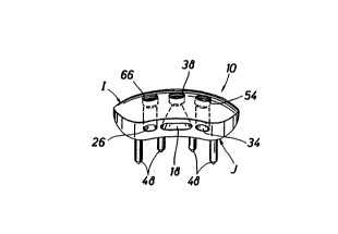
The clamp 10, as shown in detail in Figs. 3-7, has
an outer surface I that is generally convex and an
inner surface J that faces the removed bone section and
that is generally concave. Three parallel through
bores 18, 26 and 34 extend laterally through the entire
width of the clamp 10 from one side to the other to
form openings on opposite sides G and H of the clamp 10
through which cable is threaded. These bores 18, 26
and 34 then provide a means for holding cable in a
fixed position relative to the outer surface I o~ the
clamp 10. As shown in Fig. 5, the through bores do not
necessarily follow the curved contour of the clamp 10
but the ~ores may do so, although such may be more
difficult to machine.
As shown in Figs. 3-6, the through bore 18 is
formed in the center of the width of the clamp 10. The
through bore 18 is formed with openings flaring
outwardly from its median point at the center of the
clamp 10 to the sides G and H so that the clamp is
universal in the sense that it can be used on both the
left and right femurs and does not have to be oriented
in a particular direction. The through bores 26 and 34
are located on either side of the central through bore
18. Both o~ the through bores 26 and 34 are ~ormed in
a generally tubular shape. (Fig. 4) ~he size of each
through bore is preferably sufficient to accommodate
the thickness of two surgical cables as discussed
below.
It is desirable to affix the clamp 10 and removed
bone section W to the greater trochanter with tensioned
cable. Thus, the clamp 10 has means operatively
associated with its outer surface for cooperating in
clamping a tensioned cable. These means cooperate with
9 2133116
means for forcing the cable ag~inst the inner surfaces
of the through bores. Thus, in this example, the means
for clamping the cable to the clamp 10 for holding the
removed bone section in place, includes: means
S operatively associated with the outer surface of the
clamp 10; means for forcing the cable; and the inner
surfaces of the through bores. Referring to Fig. 6, a
threaded opening 38 is formed in the center of the
upper surface of the clamp 10 substantially
perpendicular to and intersecting with the through bore
18. Threaded openings 54 and 66 are similarly formed
~ in the clamp 10 with respect to the through bores 34
j and 26. The threaded openings 38, 54 and 66 extend
into but not through the through bores 18, 34 and 26,
j 15 so that the cable can be clamped between the inner
¦ surfaces 71 of the through bores and a cooperating
means for clamping the cable, such as a bolt or screw,
as discussed below.
As shown in Fig. 2, the clamp 10 is installed by
passing a length of cable 50 through the hole A and
threading the ends through opposite sides of the
through bore 26. A second cable 52 is passed through
the hole B, with both ends being threaded through
opposite sides of the through bore 34. A third cable ~
54 is centered on the lower side adjacent to the ;
lateral aspect o~ the ~emur or adjacent to the lateral
cortex and wrapped through hole C and then threaded
through bore 18.
The cables 50, 52 and 54 are about 1.6 - 2.0 mm.
in diameter, with the holes A, B and C slightly larger.
The cables are preferabIy formed of braided strands of
chrome-cobalt wire. However, cables formed of wires of
other biocompatible metals, as well as biocompatible
organic polymeric cables or polymer monofilaments,
3s could alco be used.
.,~.,
. ~ ~,
.,
~ ' .'''
21331~6
---- 10
As shown in Fig. 8, afte~ the cables 50, 52 and 54
are threaded through the through bores 26, 34 and 18,
the respective ends of the cables are grasped by cable
tensioners T on the opposite side of the clamp 10 from
where each was inserted. The cable tensioners T are
used to apply tension to the cables 50, 52 and 54 until
tension is evenly applied across the surface of the
clamp 10. The preferred tension in the wire 50, 52 and
54 generally ranges from about 125 to about 200 pounds.
Referring to Figs. 8 and 9, assembly of the cable
system is completed by fastening a clamping screw 20
into each threaded opening 38, 54 and 66 to clamp or
anchor the cables 50, 52 and 54 against the inner
surfaces 71 of the through bores 18, 34 and 26. The
cables are positively engaged across the entire surface
of the base of each of the screws 20 by controlled
tightening of the screws.
As shown in Fig. 9, after the screws 20 are
tightened to clamp the cables against the inner
surfaces 71 of the through bores, the tensioners T are
released and removed. The ends of the wires 50, 52 and
54 are then trimmed so that the ends lie within their
re~pective through bores in clamp 10. The trimming
operation is preferably performed using a guillotine
type cutrer (not shown) to minimize the possibility of
the cable ends ~raying. The clamp could also be ~ormed
with countersunk holes (not shown) so that cancellous
bone screws could be used as a supplemental connection
to the underlying bone for additional initial -~
stability.
The invention is directed primarily to the use of
mechanical clamping elements for clamping the cables
50, 52 and 54 in place in the through bores 26, 34 and
18. While the screws 20 are described in conjunction -
with the threaded openings 38, 54 and 66, other means
11 - 2 1 3 3 1 1 6
for holding the cables in place, in the manner
described, could also be used.
By using clamps, along with the clamping devices
; and cables as described above, a greater trochanter or
other bone section can be reattached after surgery and
held firmly in place during the healing process.
Rotating and shifting of the clamp and reattached bone
section when the patient walks or rises out of a
sitting position are resisted because the cables and
lo clamp are positioned to counteract the forces acting on
the clamp.
The foregoing disclosure and description of the
invention are illustrative and explanatory thereof.
; Upon reading this disclosure, various changes in the
size, shape, and materials, as well as in the details
o~ the illustrated construction may become apparent to
one of ordinary skill in the art. These are within the
scope and spirit of the invention as disclosed above
ond claimed below.
~..
., . .~
'~' .''
'.~
. ,,.. ~
-', .: