Note: Descriptions are shown in the official language in which they were submitted.
30145
~ (920-87)
~ 1 3 3 2 7 4
~
:. `
~ ,~ ,,: ;: ::
: :... .
: .'.;',~.', ~
FOLDABLE ELECT~ICAL BOX .~: ~
~''' '"'~'''`'
;
Field of the Invention
The present invention relates to an electrical box for ~ ~
mounting an electrical wiring device to a support member. ~ :
More specifically, this invention relates to an electrical
box folded from a thin metallic blank of sheet material.
Preferably, the electrical box includes an integral :
mounting bracket, or mounting fasteners which also
reinforces the electrical box.
..:
'~ '''~'', . . ' .
. . :-. .
: ~:::
............. . ~
`' ` ; ~
~:' :.:
~ ~ .
-- 2
-
` 213327~
sack~round of the Invention
Electrical boxes are constructed in a variety of ways
for housing electrical wiring devices such as electrical
receptacles or outlets, switches, etc. Electrical boxes
can be constructed of either metal or plastic depending
upon the desired application for the electrical box.
Often, electrical boxes have a bracket or some other
mounting structure for securing the electrical box to a
stud or some other support member. Since numerous
electrical boxes are typically installed in a building or
house, it is important that the electrical box as well as
the mounting structure be inexpensive to manufacture, easy
to install and reliable.
Metal electrical boxes are typically constructed of
1~ sheet metal or die casted of aluminum or any other suitable
metallic material. Sheet metal electrical boxes can be
formed by bending, welding and otherwise fastening metal
panels together to form a box with an open end. The
mounting bracket is typically welded to one side of the
electrical box or attached to the electrical box by screws
or other fasteners. Some sheet metal electrical boxes have
the bracket integrally formed with one side of the
electrical box.
Examples of some prior electrical boxes with mounting
2S brackets are disclosed in the following U.S. Patents:
1,705,768 to Johnson et al; 2,644,600 to Senif; 3,588,019
to Cozeck et al; 3,834,658 to Theodorides; 4,135,337 to
Medlin; 4,140,293 to Hansen; 4,447,030 to Nattel; 4,533,060
to Medlin; 4,572,391 to Medlin; 4,603,789 to Medlin, Sr.; i
4,880,128 to Jorgensen; and 5,025,944 to Rodick.
Many of these electrical boxes with mounting brackets
have numerous disadvantages. For example, many of these
electrical boxes with brackets are very complex designs
which are difficult to install, require close manufacturing
., . ., ~ ,.. .
... . . .
. .. :,,,.: .,
i , . - . . ..
. : ... . :..,
~ :', '' ' '
,
- 3 -
- .;
21t~327~
tolerances and are difficult to manufacture at low costs.
In addition, many of the mounting brackets of these
electrical boxes cause the finished dry wall plaster to
bulge. ~-
In view of the above, it is apparent that there exists
a need to provide an electrical box with a mounting bracket
which is relatively inexpensive to manufacture and easy to
install. This invention addresses this need in the art
along with other needs which will become apparent to those
skilled in the art once given this disclosure.
Summarv of the Invention
A primary object of the subject invention is to
provide an electrical box formed by folding a thin sheet of
material.
A further object of the invention is to provide an
electrical box which is relatively inexpensive and simple
to manufacture.
A further object of the invention is to provide an
electrical box which minimizes waste during manufacture
thereof.
Still another object of the present invention is to
provide an electrical box which is easy to install and
reliable.
Still another object of the invention is to provide an
electrical box with a mounting bracket having a thin -~
mounting tab to avoid bulging the dry wall plaster.
Yet another object of the invention is to provide a
foldable electrical box with mounting fasteners which also
reinforces the electrical box and prevents unfolding of the
electrical box.
The foregoing objects are basically attained by
providing an electrical box assembly formed by folding a
unitary blank of sheet material, comprising: an electrical
~ . .
. : .
,.. .. .
~ - 4 - 2133274
~ox including a first substantially planar panel, a second
substantially planar panel coupled to the first panel by a
first fold line and extending substantially perpendicular
to the first panel, a third substantially planar panel
coupled to the first panel by a second fold line and
extending substantially perpendicular to the first panel,
a fourth substantially planar panel coupled to the first
panel by a third fold line and extending substantially
perpendicular to the first panel, and a fifth substantially
planar panel coupled to the first panel by a fourth fold
line and extending substantially perpendicular to the first
panel; and a mounting bracket including a first bracket
portion extending from the second panel in a first
direction for mounting the electrical box to a support
member, a first reinforcing panel coupled to the first
bracket portion by a fifth fold line to overlie a part of
the first bracket portion, a second bracket portion
extending from the second panel in a second direction
substantially opposite to the first direction for mounting
the electrical box to the support member, and a second
reinforcing panel coupled to the second bracket portion by
a sixth fold line to overlie a part of the second bracket
portion.
Other objects, advantages, and salient features of the
invention will become apparent from the following detailed
description, which, taken in conjunction with the annexed
drawings, discloses several preferred embodiments of the
invention.
Brief DescriDtion of the Drawinas
Referring now to the drawings which form part of this
original disclosure:
Figure 1 is a top plan view of a unitary blank of
sheet material with fold lines indicated by broken lines
"-, ~
~ '.' .. ' .
- 5 - ~3327~
for constructing an electrical box with a mounting bracket
in accordance with a first embodiment of the present
invention;
Figure 2 is a right, front perspective view of an
electrical box with a mounting bracket formed by folding
the unitary blank of sheet material illustrated in Figure
l;
Figure 3 is a front elevational view of the electrical
box and integral mounting bracket coupled to a stud or
support member;
Figure 4 is a left side elevational view of the
electrical box and integral mounting bracket illustrated in
Figures 2 and 3;
Figure 5 is a right side elevational view of the
electrical box and integral mounting bracket illustrated in
Figures 2-4;
Figure 6 is a top plan view of the electrical box and
integral mounting bracket illustrated in Figures 2-5;
Figure 7 is a top plan view of a unitary blan~ of
sheet material with fold lines indicated by broken lines
for constructing an electrical box with a mounting bracket
in accordance with a second embodiment of the present
invention;
Figure 8 is a right, front perspective view of an
electrical box with a mounting bracket formed by folding
the unitary blank of sheet material illustrated in Figure
7;
Figure 9 is a top plan view of a unitary blank of
sheet material with fold lines indicated by broken lines
for constructing an electrical box in accordance with a
third embodiment of the present invention; and
Figure 10 is a right, front perspective view of an
electrical box formed by folding the unitary blank of sheet
material illustrated in Figure 9.
,: . '.' 7
, ~ -, ,` ..
:' ' , ` _
'' ' ' ~ - .
~,' ., . ' .' .~ . ',.
~,
" '~'" "''' ''
- 6 - ~133274
Detailed Description of the Invention
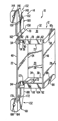
Initially referring to Figures 1 and 2, an electrical
box assembly 10 in accordance with the present invention is
illustrated, and includes an electrical box or housing 12
in the form of a wall or junction box and an integral
mounting bracket 14 formed by folding a unitary, one-piece
blank of sheet material. The mounting bracket 14 is
adapted to be fixedly secured to a stud or support member
16 as seen in Figure 3.
Preferably, the unitary blank of sheet material
forming electrical box assembly 10 is a conventional
metallic material, such as galvanized steel or aluminum.
Due to the unique folding pattern of electrical box
assembly 10, the unitary blank of sheet material can be
thinner than the sheet material used for conventional
electrical boxes and mounting brackets. In particular, the
unitary blank of sheet material, preferably has a thickness
of about 0.030 inch to about 0.031 inch, while conventional
electrical boxes and mounting brackets have a thickness of
about 0.0625 inch. The unitary blank of sheet material
utilized to construct electrical box assembly 10 is first
stamped to form the blank as seen in Figure 1, and then
folded to form an integral, one piece, unitary electrical
box assembly 10 as discussed below in more detail. Also,
a plurality of conventional break-out windows and/or
auxiliary holes (not shown) can be stamped into the unitary
blank as needed or desired. Accordingly, electrical box
assembly 10 is formed without welding or utilizing separate
fastening members or welds.
As seen in Figure 2, when the unitary blank of sheet
material is folded, electrical box assembly 10 forms
electrical box 12 and mounting bracket 14. The electrical
box 12 of electrical box assembly 10 includes a rear wall
portion or panel 20, a first side wall portion or panel 22
.; . :
"1 ~
, ' '' '': '~-"
, `,, " ~`~
7 -
coupled to rear wall panel 20 by a first fold line 24, a
second side wall portion or panel 26 coupled to rear wall
panel 20 by fold line 28, a first end wall portion or panel
30 coupled to rear wall panel 20 by a third fold line 32,
and a second end wall portion or panel 34 coupled to rear
panel 20 by a fourth fold line 36.
Electrical box 12, as illustrated herein, forms a two
inch deep single gang electrical box. Of course, it would
be apparent to those skilled in the art, that electrical
box 12 could have a variety of shapes or sizes without
departing from the subject invention. As seen in Figure 1,
rear wall panel 20, first side wall panel 22 and second
side wall panel 26 are flat substantially planar members
having substantially the same size. In particular, fold
lines 24 and 28 are substantially parallel and form a pair
of opposite edges of rear wall panel 20. Fold lines 32 and
36 are substantially parallel and form the second pair of
opposite edges of rear wall panel 20.
First side wall panel 22 has a free edge 40 which is
substantially parallel to the edge formed by first fold
line 24, and a pair of opposite, parallel edges 42 and 44
extending perpendicularly between free edge 40 and fold
line 24. Edges 42 and 44 are substantially aligned with
fold lines 32 and 36, respectively. When electrical box 12
is folded, side wall panel 22 is bent along first fold line
24 to extend substantially perpendicular to rear wall panel
20.
Second side wall panel 26 has a free edge 46 extending
substantially parallel to the edge formed by second fold
line 28, and a pair of opposite, parallel edges 48 and 50
between free edge 46 and fold line 28. Edges 48 and 50 are ;
substantially perpendicular to fold line 28 and free edge
46, and are substantially aligned with fold lines 32 and
36, respectively. When electrical box 12 is folded, second
. .
- : ~
,.~,, .~. ;.
'- , ~
- 8 - 2133274
side wall panel 26 is bent along second fold line 28 to
extend substantially perpendicular from rear wall panel 20
and substantially parallel to first side wall panel 22.
First end wall panel 30 has a substantially flat,
planar, rectangular shape. Accordingly, first end wall
panel 30 has a first pair of opposite, parallel edges
formed by fold line 32 and a fold line 64 together with a
free edge 52, and a second pair of opposite, parallel edges
formed by fold line 60 and a free edge 70. A first
coupling flap 54 is coupled to first end wall panel 30 by
a fold line 56 for engaging first side wall panel 22. A
second coupling flap 58 is coupled to first end wall panel
30 by fold line 60 for engaging second side wall panel 26.
A wiring device mounting flange 62 is coupled to first end
wall panel 30 by fold line 64 for attaching a wiring device
(not shown) to electrical box 12. When electrical box 12
is folded, first end wall panel 30 is bent along fold line
32 to extend substantially perpendicular to rear wall panel
20.
First coupling flap 54 is a substantially flat, planar
half circular ~ember. When first coupling flap 54 is
folded along fold line 56, coupling flap 54 extends
substantially perpendicular to first end wall panel 30 for
engaging the exterior surface of first side wall panel 22.
Accordingly, coupling flap 54 holds first end wall panel 30
substantially perpendicular to first side wall panel 22,
and provides rigidity to electrical box 12. Fold line 56
is substantially parallel to edge 70 of first end wall
panel 30 and spaced approximately the thickness of first
side wall panel 22 from edge 70. Fold line 56 is also
substantially parallel to fold line 60.
Second coupling flap 58 is substantially rectangular
with a pair of rounded corners, and is bent along fold line
60 to extend substantially perpendicular to first end wall
_ . . ~
' ~. ,-,~:','.. ''Y .
, ., ~,
.. ..:
, . :, : ,...
,. ,:, .. . ~ . ~ :
9 ~133274
panel 30 for engaging the exterior surface of second side
wall panel 26. Accordingly, coupling flap 58 holds first
end wall panel 30 substantially perpendicular to second
side wall panel 26, and provides rigidity to electrical box
12. Fold line 60 forms one of the edges of first end wall
panel 30.
Wiring device moun~ing flange 62 includes a
rectangular mounting portion 72 coupled to first end wall
panel 30 by fold line 64, and a grounding portion 74
coupled to mounting portion 72 by a fold line 76. Mounting
flange 62 extends between first side wall panel 22 and
second side wall panel 26 so that an edge of mounting
portion 72 engayes second side wall panel 26 and grounding
portion 74 engages first side wall panel 22. Accordingly,
mounting flange 62 abuts against the interior surfaces of
side wall panels 22 and 26 to prevent them from folding ~ -
inwardly.
Mounting portion 72 is bent along fold line 64 to
extend substantially perpendicular to first end wall panel
20 30 from its free edge 52. Mounting portion 72 has a hole
78 formed therein for receiving a mounting screw (not
shown) from a wiring device (not shown). Mounting hole 78
can be either tapped in a conventional manner, or the
electrical box assembly 10 can be provided with self-
tapping screws so the consumer can tap hole 78 when
installing a wiring device. ~-
Grounding portion 74 has a first or central portion 80
which is substantially parallel to mounting portion 72, a
second or end portion 82 coupled to first portion 80 by
fold line 84, and a third or end portion 86 coupled to
first portion 80 by fold line 88 and coupled to mounting
portion 72 by fold line 76. Second and third portions 82
and 86 are bent along fold lines 84, 88 and 76 so that they
extend substantially perpendicular from first portion 80.
.. ~ .. , . .... ..,~
:'' ' ~ . ' r
- - lo- 2~33274
~irst portion 80 has a mounting hole 81 for threadedly
receiving a grounding screw ~not shown).
Second end wall panel 34 is substantially identical to
first end wall panel 30, except that second wall panel 34
is a mirror image of first end wall portion 30.
Second end wall panel 34 has a substantially flat,
planar, rectangular shape. Accordingly, second end wall
panel 34 has a first pair of opposite, parallel edges
formed by fold line 36 and a fold line 104 together with a
free edge 91, and a second pair of opposite, parallel edges
formed by fold line 90 and a free edge llO. A first
coupling flap 94 is coupled to second end wall panel 34 by
a fold line 96 for engaging first side wall panel 22. A
second coupling flap 98 is coupled to second end wall panel
34 by fold line 90 for engaging second side wall panel 26.
A wiring device mounting flange 92 is coupled to second end
wall panel 34 by fold line 104 for attaching a wiring
device (not shown) to electrical box 12. When electrical
box 12 is folded, second end wall panel 34 is bent along
fold line 36 to extend substantially perpendicular to rear
wall panel 20.
First coupling flap 94 is a substantially flat, planar
half cixcular member. When first coupling flap 94 is
folded along fold line 96, coupling flap 94 extends
substantially perpendicular to second end wall panel 34 for
engaging the exterior surface of first side wall panel 22.
Accordingly, coupling flap 94 holds second end wall panel
34 substantially perpendicular to first side wall panel 22,
and provides rigidity to electrical box 12. Fold line 96
is substantially parallel to edge 110 of second end wall
panel 34 and spaced approximately the thickness of first
side wall panel 22 from edge llO. Fold line 96 is also
substantially parallel to fold line 90.
. . .
. A . ,, ~,
- 11- 2~332
Second coupling flap 98 is substantially rectangular
with a pair of rounded corners, and is bent along fold line
90 to extend substantially perpendicular to second end wall
panel 34 for engaging the exterior surface of second side
wall panel 26. Accordingly, coupling flap 98 holds second
end wall panel 34 substantially perpendicular to second
side wall panel 26, and provides rigidity to electrical box
12. Fold line 90 forms one of the edges of second end wall
panel 134. Fold line 90 extends substantially parallel to
fold line 28, and is spaced approximately the thickness of
second side wall panel 26 from fold line 28.
Wiring device mounting flange 92 includes a
rectangular mounting portion 112 coupled to second end wall
panel 34 by fold line 104, and a grounding portion 114
coupled to mounting portion 112 by a fold line 116.
Mounting flange 92 extends between first side wall panel 22
and second side wall panel 26 so that an edge of mounting
portion 112 engages second side wall panel 26 and grounding
portion 74 engages first side wall panel 22. Accordingly,
mounting flange 92 abuts against the interior surfaces of
side wall panels 22 and 26 to prevent them from folding
inwardly.
Mounting portion 112 is bent along fold line 104 to
extend substantially perpendicular to second end wall panel
34 from its free edge 91. Mounting portion 112 has a hole
118 formed therein for receiving a mounting screw (not
shown) from a wiring device (not shown). Mounting hole 118
can be either tapped in a conventional manner, or the
electrical box assembly 10 can be provided with self-
tapping screws so the consu~er can tap hole 118 when
installing a wiring device.
Grounding portion 114 has a first or central portion
120 which is substantially parallel to mounting portion
112, a second or end portion 122 coupled to first portion
. "; : :.. ,' ` ~ ~
.~, ~'''''
. '`~ ~ '.'~ ,
, - 12 21 33 2
120 by fold line 124, and a third or end portion 126
coupled to first portion 120 by fold line 128 and coupled
to mounting portion 112 by fold line 116. Second and third
portions 122 and 126 are bent along fold lines 116, 124 and
128 to extend substantially perpendicular from first
portion 120. First portion 120 has a mounting hole 121 for
threadedly receiving a grounding screw (not shown).
Bracket 14 includes a first bracket portion 130 and a
second bracket portion 132 integrally formed with first
side wall panel 22. In particular, first bracket portion
130 is coupled to first side wall panel 22 by fold line 134
which lies on edge 42 of side wall panel 22. Second
bracket portion 132 is coupled to side wall panel 22 by
fold line 136 which lies on edge 44 of side wall panel 22.
Bracket portions 130 and 132 are preferably spaced one-half
inch from edge 40 of side wall panel 22 so that electrical
box 12 is flush with one-half inch thick dry wall when
coupled to support member 16.
First bracket portion 130 includes a first side
mounting section 140, a face mounting section 144 with a
mounting hole 146, a pair of reinforcing panels 150 and 152
coupled to side mounting section 140 by fold lines 154 and
156, respectively. Side mounting section 140 includes a
first portion 158 and a second portion 160 coupled to first
portion 158 by fold line 162. First portion 158 is
substantially rectangular and extends outwardly from side
wall panel 22 at an angle of approximately 135 when
assembled as seen in Figure 3. Second portion 160 extends
outwardly from first portion 158 and is substantially
parallel to side wall panel 22. Accordingly, side mounting
section 140 spaces side wall panel 22 from support member
16 as seen in Figure 3.
Reinforcing panels 150 and 152 are folded along fold
lines 154 and 156 to overlie first and second portions 158
.' ~ '',", ', . :. ';-
~.',;' ' ~
. - -;:. :,
- . ~
- 13 - 21 3 3 2 74
and 160 for doubling the thickness of first bracket portion
130 along first side mounting section 140. Accordingly,
reinforcing panels 150 and 152 permit bracket portion 130
to be constructed of a thin sheet material so that face
mounting section 144 is a single thickness while side
mounting section is a double thickness. This arrangement
minimizes the bulging of the dry wall plaster, while still
providing a strong and rigid bracket.
Second bracket portion 132 includes a first side
mounting section 161, a face mounting section 164 with a
mounting hole 166, a pair of reinforcing panels 170 and 172
coupled to side mounting section 161 by fold lines 174 and
176, respectively. Side mounting section 161 includes a
first portion 178 and a second portion 180 coupled to first
portion 178 by fold line 182. First portion 178 is
substantially rectangular and extends outwardly from side
wall panel 22 at an angle of approximately 135 when
assembled as seen in Figure 3. Second portion 180 extends
outwardly from first portion 178 and is substantially
parallel to side wall panel 22. Accordingly, side mounting
section 161 spaces side wall panel 22 from the support
member 16 as seen in Figure 3.
Reinforcing panels 170 and 172 are folded along fold
lines 174 and 176 to overlie first and second portions 178
and 180 for doubling the thickness of second bracket
portion 132 along first side mounting section 161.
Accordingly, reinforcing panels 170 and 172 permit bracket
portion 132 to be constructed of a thin sheet material so
that face mounting section 164 is a single thickness while
side mounting section 161 is a double thickness. This
arrangement minimizes the bulging of the dry wall plaster,
while still providing a strong and rigid bracket.
:~ r
~, ' ,' ' ''
, ~'' :'~' ', '
; I . h'
' ' ~ " -' ' '
" ~'' ~.'' ,''' '.
': , . ' : .
.
' ' ' ~ '
~ - 14 - 2~3327~
Construction of Electrical Box AssemblY 10
In constructing electrical box assembly 10, first a
blank is stamped out of sheet metal as seen in Figure 1.
Then, electrical box 12 and mounting bracket 14 are formed
by bending the blank of sheet metal along the various fold
lines illustrated by broken lines in Figure 1. It will be
apparent to those skilled in the art once given this
disclosure that the blank of sheet metal generally does not
have to be bent along the fold lines in any particular
order.
Electrical Box Assemblv 210 of Fiqures 7 and 8
Initially referring to Figures 7 and 8, an electrical
box assembly 210 in accordance with the present invention
is illustrated, and includes an electrical box or housing
212 in the form of a wall or junction box and an integral
mounting bracket 214 formed by folding a unitary, one-piece
blank of sheet material. The mounting bracket 214 is
adapted to be fixedly secured to a stud or support member
216 as seen in Figures 8. Electrical box assembly 210 is
substantially identical to electrical box assembly 10 as
discussed above, except that the mounting bracket 14 has
been modified. Thus, electrical box assembly 210 will not
be illustrated in detail herein.
Preferably, the unitary blank of sheet material
forming electrical box assembly 210 is a conventional
metallic material, such as galvanized steel or aluminum.
Due to the unique folding pattern of electrical box -
assembly 210, the unitary blank of sheet material can be b~
thinner than the sheet material used for conventional
electrical boxes and mounting brackets. In particular, the
unitary blank of sheet material, preferably has a thickness
of about 0.030 inch to about 0.031 inch, while conventional
electrical boxes and mounting brackets have a thickness of
:. ,~~ ~,:, .
,, ~ . .
'~ ^ " ' ;`~ '. ' .'~
- 15 - 2133274
about 0.0625 inch. The unitary blank of sheet material
utilized to construct electrical box assembly 210 is first -~
stamped to form the blank as seen in Figure 7, and then
folded to form an integral, one piece, unitary electrical
box assembly 210 as discussed below in more detail. Also,
a plurality of conventional break-out windows and/or
auxiliary holes (not shown) can be stamped into the unitary
blank as needed or desired. Accordingly, electrical box
assembly 210 is formed without welding or utilizing
separate fastening members or welds.
As seen in Figure 8, when the unitary blank of sheet
material is folded, electrical box assembly 210 forms
electrical box 212 and mounting bracket 214. The
electrical box 212 of electrical box assembly 210 includes
a rear wall portion or panel 220, a first side wall portion
or panel 222 coupled to rear wall panel 220 by a first fold
line 224, a second side wall portion or panel 226 coupled
to rear wall panel 220 by fold line 228, a first end wall
portion or panel 230 coupled to rear wall panel 220 by a
third fold line 232, and a second end wall portion or panel
234 coupled to rear panel 220 by a fourth fold line 236.
Electrical box 212, as illustrated herein, forms a two
inch deep single gang electrical box. Of course, it would
be apparent to those skilled in the art, that electrical
box 212 could have a variety of shapes or sizes without
departing from the subject invention. As seen in Figures
7 and 8, rear wall panel 220, first side wall panel 222 and
second side wall panel 226 are flat substantially planar
members having substantially the same size. In particular,
fold lines 224 and 228 are substantially parallel and form
a pair of opposite edges of rear wall panel 220. Fold
lines 232 and 236 are substantially parallel and form the
second pair of opposite edges of rear wall panel 220. ~;~
.- . , -- _ ....--
~ . . ,,, . j .;. ,
~ ~ , . ",, ., ;, . .
~'':.... i.
,'. . . ' . '~
- 16 - 2133274
First side wall panel 222 has a free edge 240 which is
substantially parallel to the edge formed by first fold
line 224, and a pair of opposite, parallel edges 242 and
244 extending perpendicularly between free edge 240 and
5fold line 224. Edges 242 and 244 are substantially aligned
with fold lines 232 and 236, respectively. When electrical
box 212 is folded, side wall panel 222 is bent along first
fold line 224 to extend substantially perpendicular to rear
wall panel 220.
lOSecond side wall panel 226 has a free edge 246
extending substantially parallel to the edge formed by
second fold line 228, and a pair of opposite, parallel
edges 248 and 250 between free edge 246 and fold line 228.
Edges 248 and 250 are substantially perpendicular to fold
15line 228 and free edge 246, and are substantially aligned
with fold lines 232 and 236, respectively. When electrical
box 212 is folded, second side wall panel 226 is bent along
second fold line 228 to extend substantially perpendicular
from rear wall panel 220 and substantially parallel to
first side wall panel 222.
First end wall panel 230 has a substantially flat,
planar, rectangular shape. Accordingly, first end wall
panel 230 has a first pair of opposite, parallel edges
formed by fold line 232 and a fold line 264 together with
a free edge 252, and a second pair of opposite, parallel
edges formed by fold line 260 and a free edge 270. A first
coupling flap 254 is coupled to first end wall panel 230 by
a fold line 256 for engaging first side wall panel 222. A
second coupling flap 258 is coupled to first end wall panel
230 by fold line 260 for engaging second side wall panel
226. A wiring device mounting flange 262 is coupled to
first end wall panel 230 by fold line 264 for attaching a
wiring device (not shown) to electrical box 212. When
electrical box 212 is folded, first end wall panel 230 is
: ~ , ,-
" :,
, ,, . ,, ~
.17 - 2133279
bent along fold line 232 to extend substantially
perpendicular to rear wall panel. 220.
First coupling flap 254 is a substantially flat,
planar half circular member. When first coupling flap 254
5 is folded along fold line 256, coupling flap 254 extends
substantially perpendi.cular to first end wall panel 230 for
engaging the exterior su~face of first side wall panel 222.
Accordingly, coupling flap 254 holds first end wall panel
230 substantially perpendicular to first side wall panel
10222, and provides rigidity to electrical box 212. Fold
line 256 is substantially parallel to edge 270 of first end
wall panel 230 and spaced approximately the thickness of
first side wall panel 222 from edge 270. Fold line 256 is
also substantially parallel to fold line 260.
15Second coupling flap 258 is substantially rectangular
with a pair of rounded corners, and is bent along fold line
260 to extend substantially perpendicular to first end wall
panel 230 for engaging the exterior surface of second side
wall panel 226. Accordingly, coupling flap 258 holds first
end wall panel 230 substantially perpendicular to second
side wall panel 226, and provides rigidity to electrical
box 212. Fold line 260 forms one of the edges o~ first end :
wall panel 230.
Wiring device mounting flange 262 includes a
rectangular mounting portion 272 coupled to first end wall
panel 230 by fold line 264, and a grounding portion 274
coupled to mounting portion 272 by a fold line 276.
Mounting flange 262 extends between first side wall panel
222 and second side wall panel 226 so that an edge of
mounting portion 272 engages second side wall panel 226 and
grounding portion 274 engages first side wall panel 222.
Accordingly, mounting flange 262 abuts against the interior
surfaces of side wall panels 222 and 226 to prevent them
from folding inwardly.
' , ': ', ,: '
s ' . ~ ,; "'
r~
~ ":' ' ': ' `
" ' -' - '', -.~ ,",
: ' .
. .
1~- 2~33274
Mountinq portion 272 is bent along fold line 264 to
extend substantially perpendicular to first end wall panel
230 from its free edge 252. Mounting portion 272 has a
hole 278 formed therein for receiving a mounting screw (not
shown) from a wiring device (not shown). Mounting hole 278
can be either tapped in a conventional manner, or the
electrical box assembly 210 can be provided with self-
tapping screws so the consumer can tap hole 278 when
installing a wiring device.
Grounding portion 274 has a first or central portion
280 which is substantially parallel to mounting portion
272, a second or end portion 282 coupled to first portion
280 by fold line 284, and a third or end portion 286
coupled to first portion 280 by fold line 288 and coupled
to mounting portion 272 by fold line 276. Second and third
portions 282 and 286 are bent along fold lines 284, 288 and ;
276 so that they extend substantially perpendicular from
first portion 280. First portion 280 has a mounting hole
281 for threadedly receiving a grounding screw (not shown).
Second end wall panel 234 is substantially identical
to first end wall panel 230, except that second wall panel
234 is a mirror image of first end wall portion 230. ; ~--
Second end wall panel 234 has a substantially flat,
planar, rectangular shape. Accordingly, second end wall
panel 234 has a first pair of opposite, parallel edges
formed by fold line 236 and a fold line 304 together with
a free edge 291, and a second pair of opposite, parallel
edges formed by fold line 290 and a free edge 310. A first
coupling flap 294 is coupled to second end wall panel 234
by a fold line 296 for engaging first side wall panel 222. -~
A second coupling flap 298 is coupled to second end wall
panel 234 by fold line 290 for engaging second side wall
panel 226. A wiring device mounting flange 292 is coupled
to second end wall panel 234 by fold line 304 for attaching
:"~'"'.' ~,~':'
;.,,. .,. ,: ~ ~:
. ~ :, , :,
., ., .
- 19- ~133274
a wiring device (not shown) to electrical box 212. When
electrical box 212 is folded, second end wall panel 234 is
bent along fold line 236 to extend substantially
perpendicular to rear wall panel 220.
First coupling flap 294 is a substantially flat,
planar half circular member. When first coupling flap 294
is folded along fold line 296, coupling flap 294 extends
substantially perpendicular to second end wall panel 234
for engaging the exterior surface of first side wall panel
222. Accordingly, coupling flap 294 holds second end wall
panel 234 substantially perpendicular to first side wall
panel 222, and provides rigidity to electrical box 212.
Fold line 296 is substantially parallel to edge 310 of
second end wall panel 234 and spaced approximately the
thickness of first side wall panel 222 from edge 310. Fold
line 296 is also substantially parallel to fold line 290.
Second coupling flap 298 is substantially rectangular
with a pair of rounded corners, and is bent along fold line
290 to extend substantially perpendicular to second end
wall panel 234 for engaging the exterior surface of second
side wall panel 226. Accordingly, coupling flap 298 holds
second end wall panel 234 substantially perpendicular to
second side wall panel 226, and provides rigidity to
electrical box 212. Fold line 290 forms one of the edges
of second end wall panel 334. Fold line 290 extends
substantially parallel to fold line 228, and is spaced
approximately the thickness of second side wall panel 226
from fold line 228.
Wiring device mounting flange 29~ includes a
rectangular mounting portion 312 coupled to second end wall
panel 234 by fold line 304, and a grounding portion 314
coupled to mounting portion 312 by a fold line 316.
Mounting flange 292 extends between first side wall panel
222 and second side wall panel 226 so that an edge of
~, ~. ,~,...
... ,.`.~. .~ ^. . . .
- 5 ~
- 20 - 213327~
mounting portion 312 engages second side wall panel 226 and
grounding portion 274 engages first side wall panel 222.
Accordingly, mounting flange 292 abuts against the interior
surfaces of side wall panels 222 and 226 to prevent them
from folding inwardly.
Mounting portion 312 is bent along fold line 304 to
extend substantially perpendicular to second end wall panel
234 from its free edge 291. Mounting portion 312 has a
hole 318 formed therein for receiving a mounting screw (not
shown) from a wiring device (not shown). Mounting hole 318
can be either tapped in a conventional manner, or the
electrical box assembly 210 can be provided with self~
tapping screws so the consumer can tap hole 318 when
installing a wiring device.
Grounding portion 314 has a first or central portion
320 which is substantially parallel to mounting portion
312, a second or end portion 322 coupled to first portion
320 by fold line 324, and a third or end portion 326
coupled to first portion 320 by fold line 328 and coupled
20 to mounting portion 312 by fold line 316. Second and third
portions 322 and 326 are bent along fold lines 316, 324 and
- 328 to extend substantially perpendicular from first
portion 320. First portion 320 has a mounting hole 321 for
threadedly receiving a grounding screw (not shown).
Bracket 214 includes a first bracket portion 330 and
a second bracket portion 332 integrally formed with first
side wall panel 222. In particular, first bracket portion
330 is coupled to first side wall panel 222 by fold line
334 which lies on edge 242 of side wall panel 222. Second
30 bracket portion 332 is coupled to side wall panel 222 by
fold line 336 which lies on edge 244 of side wall panel
222. Bracket portions 330 and 332 are preferably spaced
one-half inch from edge 240 of side wall panel 222 so that
. , ,, ~
. .
. -~ -- , ,
. - s . ~ .. .
.
. . , :, ~ .
. . .
,,
.: .- ' ';.:, ,
- 21 - ~13327~
electrical box 212 is flush with one-half inch thick dry
wall when coupled to support member 216.
First bracket portion 330 includes a first side
mounting section 340, a face mounting section 344 with a
pair of mounting holes 346 coupled to mounting section 340
by fold line 354. Side mounting section 340 includes a
first portion 35~ and a second portion 360 coupled to first
portion 358 by fold line 362. First portion 358 is
substantially rectangular and extends outwardly from side
wall panel 322 at an angle of approximately 13~ when
assembled. Second portion 360 extends outwardly from first
portion 358 and is substantially parallel to side wall
panel 222. Accordingly, side mounting section 340 spaces
side wall panel 222 from support member 216 as seen in
Figure 8.
Second bracket portion 332 includes a first side
mounting section 361, a face mounting section 364 with a
pair of mounting holes 366 coupled to mounting section 361
by fold line 374. Side mounting section 361 includes a
first portion 378 and a second portion 380 coupled to first
portion 378 by fold line 382. First portion 378 is
substantially rectangular and extends outwardly from side
wall panel 222 at an angle of approximately a 135 when
assembled. Second portion 380 extends outwardly from first
portion 378 and is substantially parallel to side wall
panel 222. Accordingly, side mounting section 361 spaces
side wall panel 222 from the support member 216 as seen in
Figure 8.
Electrical Box 410 of Fiqures 9 and 10
Initially referring to Figures 9 and 10, an electrical
box 410 in accordance with the present invention is
illustrated in the form of a wall or junction box.
Electrical box 410 is formed by folding a unitary, one~
. ,.., . _ ..._. . .
. .
-~ - 22 - X13327~
piece of blank of sheet material shown in Figure 9.
Electrical box 410 is substantially identical to electrical
box 12 as discussed above, except that mounting bracket 14
has been removed and coupling flanges 54 and 94 of
electrical box 12 have been modified. Thus, electrical box
410 will not be illustrated in detail herein.
Preferably, the unitary blank of sheet material
forming electrical box 410 is a conventional metallic
material, such as galvanized steel or aluminum. Due to the
unique folding pattern of electrical box 410, the unitary
blank of sheet material can be thinner than the sheet
material used for conventional folded electrical boxes. In
,.: ",
particular, the unitary blank of sheet material, preferably
has a thickness of about 0.030 inch to about 0.031 inch,
while conventional electrical boxes and mounting brackets
have a thickness of about 0.0625 inch. The unitary blank
of sheet material utilized to construct electrical box 410
is first stamped to form the blank as seen in Figure 9, and
then folded to form an integral, one piece, unitary
electrical box 410 as discussed below in more detail.
Also, a plurality of conventional break-out windows and/or
auxiliary holes (not shown) can be stamped into the unitary
blank as needed or desired. Accordingly, electrical box
410 is formed without welding or utilizing separate
fastening members or welds.
As seen in Figure 10, the unitary blank of sheet
material is folded to form electrical box 410. The
electrical box 410 includes a rear wall portion of panel
420, a first side wall portion or panel 422 coupled to rear
wall panel 420 by a first fold line 424, a second side wall
portion or panel 426 coupled to rear wall panel 420 by
fold line 428, a first end wall portion or panel 430
coupled to rear wall panel 420 by a third fold line 432,
- :
?.
t~
.-,' ' ~. '" ' ' ' '," ,
- 23 - 213327~
and a second end wall portion or panel 434 coupled to rear
panel 420 by a fourth fold line 436.
Electrical box 410, as illustrated herein, forms a two
inch deep single gang electrical box. Of course, it would
be apparent to those skilled in the art, that electrical
box 410 could have a variety of shapes or sizes without
departing from the subject invention. As seen in Figures
9 and 10, rear wall panel 420, first side wall panel 422
and second side wall panel 426 are flat substantially
planar members having substantially the same size. In
particular, fold lines 424 and 428 are substarltially
parallel and form a pair of opposite edges of rear wall
panel 42~. Fold lines 432 and 436 are substantially
parallel and form the second pair of opposite edges of rear
wall panel 420.
First side wall panel 422 has a free edge 440 which is
substantially parallel to the edge formed by first fold
line 424, and a pair of opposite, parallel edges 442 and
444 extending perpendicularly between free edge 440 and
fold line 424. Edges 442 and 444 are substantially aligned
with fold lines 432 and 436, respectively. Adjacent edge
442 of first side wall panel 422 is a mounting hole 443 for
receiving a first mounting nail 445 therethrough. Adjacent
edge 444 of first side wall panel 422 is a mounting hole
25447 for receiving a second mounting nail 449 therethrough.
When electrical box 410 is folded, side wall panel 422 is
bent along first fold line 424 to extend substantially
perpendicular to rear wall panel 420.
Second side wall panel 426 has a free edge 446
extending substantially parallel to the edge formed by
second fold line 428, and a pair of opposite, parallel
edges 448 and 450 between free edge 446 and fold line 428.
Edges 448 and 450 are substantially perpendicular to fold
line 428 and free edge 446, and are substantially aligned
,,, :
... , . ,,
. ", . ,,, .~ ~,, , ~ ,. ..
,; .- . . , ~: .
~ ~33274
with fold lines 432 and 436, respectively. Adjacent edge
448 is a mounting hole 451 for receiving first mounting
nail 445 therethrough. Likewise, adjacent edge 450 of
second side wall panel 426 is a mounting hole 453 for
receiving second mounting nail 449 therethrough. When
electrical box 410 is folded, second side wall panel 426 is
bent along second fold line 428 to extend substantially
perpendicular from rear wall panel 420 and substantially
parallel to first side wall panel 422.
First end wall panel 430 has a substantially flat,
planar, rectangular shape. Accordingly, first end wall
panel 430 has a first pair of opposite, parallel edges
formed by fold line 432 and a fold line 464 together with
a free edge 452, and a second pair of opposite, parallel
edges formed by fold line 460 and fold line 456. A first
coupling flap 454 is coupled to first end wall panel 430 by
fold line 456 for engaging first side wall panel 422. A
second coupling flap 458 is coupled to first end wall panel
430 by fold line 460 for engaging second side wall panel
426. A wiring device mounting flange 462 is coupled to
first end wall panel 430 by fold line 464 for attaching a
wiring device (not shown) to electrical box 410. When
electrical box 410 is folded, first end wall panel 430 is
bent along fold line 432 to extend substantially
perpendicular to rear wall panel 420.
First coupling flap 454 is a substantially flat,
planar rectangular member with a pair of rounded corners.
When first coupling flap 454 is folded along fold line 456
coupling flap 454 extends substantially perpendicular to
first end wall panel 430 for engaging the exterior surface
of first side wall panel 422. Accordingly, coupling flap
454 holds first end wall panel 430 substantially
perpendicular to first side wall panel 422, and provides
rigidity to electrical box 410. Coupling flap 45~ has a
~' ~
!7
: ' ~ ' ' , '. ~ : ,
.': . `' ' ' ' . -.:
~ - 25 - 213327~
mounting hole 455 which is aligned with mounting hole 443
in first side wall panel 422 for receiving mounting nail
445 therethrough. Fold line 456 forms one of the edges of
first end wall panel 430. Fold line 456 is also
substantially parallel to fold line 460 and offset from
fold line 424 by the thickness of side wall panel 422.
Second coupling flap 458 is substantially rectangular
with a pair of rounded corners, and is bent along fold line
460 to extend substantially perpendicular to first end wall
panel 430 for engaging the exterior surface of second side
wall panel 426. Accordingly, coupling flap 458 holds first
end wall panel 430 substantially perpendicular to second
side wall panel 426, and provides rigidity to electrical
box 410. Coupling flap 458 has a mounting hole 459 which
is aligned with mounting hole 451 in side wall panel 422
for receiving mounting nail 445 therethrough. Nail 445
also prevents the outward unfolding of first end wall panel
430 after installation, since nail 445 fixedly couples
coupling flaps 454 and 458 to side wall panels 422 and 426,
respectively. Fold line 460 forms one of the edges of
first end wall panel 430 and is offset from fold line 428
by the thickness of side wall panel 426.
Wiring device mounting flange 462 includes a
rectangular mounting portion 472 coupled to first end wall
panel 430 by fold line 464, and a grounding portion 474
coupled to mounting portion 472 by a fold line 476.
Mounting flange 462 extends between first side wall panel
422 and second side wall panel 426 so that an edge of
mounting po~tion 472 engages second side wall panel 426 and
grounding portion 474. Accordingly, mounting flange 462
abuts against the interior surfaces of side wall panels
422 and 426 to prevent them from folding inwardly.
Mountinq portion 472 is bent along fold line 464 to
extend substantially perpendicular to first end wall panel
. ~ , ;. ,__ . . .
.:, ~ . ..
~, . ..~.
.' ' '~ ,~ , ,
~ ~ 1 3 3 2 7 ~ ~ ~
430 from its free edge 452. Mounting portion 472 has a
hole 478 formed therein for receiving a mounting screw (not
shown) from a wirin~ device (not shown). Mounting hole 478
can be either tapped in a conventional manner, or the
electrical box 410 can be provided with self-tapping screws
so the consumer can tap hole 478 when installing a wiring
device.
Grounding portion 474 has a first or central portion
480 which is substantially parallel to mounting portion
472, a second o~ end portion 482 coupled to first portion
480 by fold line 484, and a third or end portion 486
coupled to first portion 480 by fold line 488 and coupled
to mounting portion 472 by fold line 476. Second and third
portions 482 and 486 are bent along fold lines 484, 488 and
476 so that they extend substantially perpendicular from
first portion 480. First portion 480 has a mounting hole
481 for threadedly receiving a grounding screw (not shown).
Second end wall panel 434 is substantially identical
to first end wall panel 430, except that second wall panel
434 is a mirror image of first end wall portion 430.
Second end wall panel 434 has a substantially flat,
planar, rectangular shape. Accordingly, second end wall
panel 434 has a first pair of opposite, parallel edges
formed by fold line 436 and a fold line 504 together with
a free edge 491, and a second pair of opposite, parallel
edges formed by fold line 490 and fold line 496.
A first coupling flap 494 is coupled to second end
wall panel 434 by fold line 496 for engaging first side
wall panel 422. Fold line 496 is offset from fold line 424
by the thickness of side wall panel 422 so that first
coupling flap 494 can be folded to overlie the exterior
surface of side wall panel 422. A second coupling flap 498
is coupled to second end wall panel 434 by fold line 490
for engaging second side wall panel 426. Fold line 490 is
~. .~ s
~. :~ - i . :.
"c . -; .
~` - 27 - 213~27~
offset from fold line 428 by the thickness of side wall
panel 426 so that second coupling flap 498 can be folded to
overlie the exterior surface of side wall panel 426. A
wiring device mounting flange 492 is coupled to second end
wall panel 434 by fold line 504 for attaching a wiring
device (not shown) to electrical box 410. When electrical
box 410 is folded, second end wall panel 434 is bent along
fold line 436 to extend substantially perpendicular to rear
wall panel 420.
First coupling flap 494 is a substantially flat,
planar rectangular member with a pair of rounded corners.
When first coupling flap 494 is folded along fold line 496,
coupling flap 494 extends substantially perpendicular to
second end wall panel 434 for engaging the exterior surface
of first side wall panel 422. Coupling flap 494 has a
mounting hole 495 which is aligned with mounting hole 447
in first side wall panel 422 for receiving mounting nail
449 therethrough. Accordingly, coupling flap 494 holds
second end wall panel 434 substantially perpendicular to
first side wall panel 422, and provides rigidity to
electrical box 410. Fold line 496 forms one of the edges
of second end wall panel 434 and extends substantially
parallel to fold line 490.
Second coupling flap 498 is substantially rectangular
with a pair of rounded corners, and is bent along fold line
490 to extend substantially perpendicular to second end
wall panel 434 for engaging the exterior surface of second
side wall panel 426. Coupling flap 498 has a mounting hole
499 which is aligned with mounting hole 453 in second side
wall panel 426 for receiving mounting nail 449
therethrough. Accordingly, coupling flap 498 holds second
end wall panel 434 substantially perpendicular to second
side wall panel 426, and provides rigidi'y to electrical
box 410. In other words, nail 449 prevents the outward
. . , . _ . . _ . ~
~. ~- ....
-,
:', ;, ~,.'~
, -
..
,, ~ ,: .- . .
.;
~ - 2~ - 213327~
unfolding of first end wall panel 434 after installation,
since nail 449 fixedly secures coupling flaps 494 and 498
to side wall panels 422 and 426, respectively. Fold line
490 forms one of the edges of second end wall panel 434 and
extends substantially parallel to fold line 428. Also,
fold line 490 is spaced approximately the thickness of
second side wall panel 426 from fold line 428.
Wiring device mounting flange 492 includes a
rectangular mounting portion 512 coupled to second end wall
panel 434 by fold line 504, and a grounding portion 514
coupled to mounting portion 512 by a fold line 516.
Mounting flange 492 extends between first side wall panel
422 and second side wall panel 426 so that an edge of
mounting portion 512 engages second side wall panel 426 and
grounding portion 514 engages first side wall panel 422.
Accordingly, mounting flange 492 abuts against the interior
surfaces of side wall panels 422 and 426 to prevent them
from folding inwardly.
Mounting portion 512 is bent along fold line 504 to
extend substantially perpendicular to second end wall panel
434 from its free edge 491. Mounting portion 512 has a
- hole 518 formed therein for receiving a mounting screw (not
shown) from a wiring device (not shown). Mounting hole 518
can be either tapped in a conventional manner, or the
electrical box 410 can be provided with self-tapping screws
so the consumer can tap hole 518 when installing a wiring
device.
Grounding portion 514 has a first or central portion
520 which is substantially parallel to mounting portion
512, a second or end portion 522 coupled to first portion
520 by fold line 524, and a third or end portion 526
coupled to first portion 520 by fold line 528 and coupled
to mounting portion 512 by fold line 516. Second and third
portions 522 and 526 are bent along fold lines 516, 524 and
'' ' . ~~ ~' . ~ ~ '. .
.'`~ ~ :', .
: . , ~, .. ,.. >
~ 29 ~ 213327~
528 to extend substantially perpendicular from first
portion 520. First portion 520 has a mounting hole 521 for
threadedly receiving a grounding screw (not shown).
Electrical box 410 could be sold with captive nails
445 and 449 which are retained in the respective holes of
the electrial box 410 in a conventional manner to prevent
unfolding and to allow fast installation. For example,
nails 445 and 449 can be sized to be frictionally retained
in the holes of electrical box 410, or can be provided with
detents or barbs which prevent removal of the nails 445 and
449 from the holes in the electrical box 410.
Of course, each of the electrical boxes 10, 210 and
410 can be manufactured and sold as a fully folded
electrical box as seen in Figures 2, 8 and 10, or as a flat
blank as seen in Figures 1, 7 and 9. If manufactured for
sale as a flat blank, then the fold lines of each of the
electrical boxes 10, 210 and 410 could be creased during
stamping of the blank so that the installer could fold the
electrical box at the job site. A stack of blanks one inch
high would contain approximately 32 unfolded electricai
boxes. Thus, the size of the shipping container for
unfolded electrical boxes (blanks) would be greatly reduced
over the shipping container for folded electrical boxes.
While only three embodiments have been chosen to
illustrate the present invention, it will be understood by
those skilled in the art that various changes and
modifications can be made herein without departing from
the scope of the invention as defined in the appended
claims.
. 4`:: ,5
~' ' ' ' ` :