Language selection

Search

Patent 2133356 Summary

Third-party information liability

Some of the information on this Web page has been provided by external sources. The Government of Canada is not responsible for the accuracy, reliability or currency of the information supplied by external sources. Users wishing to rely upon this information should consult directly with the source of the information. Content provided by external sources is not subject to official languages, privacy and accessibility requirements.

Claims and Abstract availability

Any discrepancies in the text and image of the Claims and Abstract are due to differing posting times. Text of the Claims and Abstract are posted:

  • At the time the application is open to public inspection;
  • At the time of issue of the patent (grant).
(12) Patent: (11) CA 2133356
(54) English Title: OPTICAL FIBRE ASSEMBLIES FOR BLOWN INSTALLATION
(54) French Title: FIBRE OPTIQUE POUR INSTALLATION SOUFFLEE
Status: Deemed expired
Bibliographic Data
(51) International Patent Classification (IPC):
  • G02B 6/44 (2006.01)
  • G02B 6/22 (1990.01)
(72) Inventors :
  • PRESTON, ROGER STEPHEN (United Kingdom)
  • SMITH, DAVID BRIAN (United Kingdom)
(73) Owners :
  • PIRELLI GENERAL PLC (United Kingdom)
(71) Applicants :
(74) Agent: KIRBY EADES GALE BAKER
(74) Associate agent:
(45) Issued: 1997-12-16
(22) Filed Date: 1994-09-30
(41) Open to Public Inspection: 1995-04-02
Examination requested: 1996-12-09
Availability of licence: N/A
(25) Language of filing: English

Patent Cooperation Treaty (PCT): No

(30) Application Priority Data:
Application No. Country/Territory Date
9320282.8 United Kingdom 1993-10-01

Abstracts

English Abstract


An optical fibre assembly for blown installation,
comprises a fibre unit having at least one optical fibre.
The unit has a coating comprising an external layer of a
material containing hollow glass beads at least some of which
project from the outer surface of the external layer. The
coating also has an inner, buffer layer of a material having
a lower modulus of elasticity than that of the material of
the external layer and an intermediate layer of material
disposed between the external and inner layers.


French Abstract

Le dispositif à fibres optiques soufflées comprend un ensemble de fibres comportant au moins une fibre optique. L'ensemble a un revêtement qui comprend une couche externe consistant en un matériau renfermant des grains de verre creux dont au moins quelques-uns font saillie de la surface extérieure de la couche externe. Le revêtement comporte également une couche d'amortissement interne faite d'un matériau possédant un module d'élasticité plus bas que celui du matériau de la couche externe ainsi qu'une couche intermédiaire de matériau placée entre les couches externe et interne.

Claims

Note: Claims are shown in the official language in which they were submitted.


CLAIMS:
1. An optical fibre assembly for blown installation,
comprising:
a fibre unit having at least one coated optical fibre,
the coating formed of at least one coating; and
an outer coating surrounding the unit, the outer coating
having an external layer with an outer surface formed of a
material containing particulate matter at least some of which
projects from the outer surface of the external layer, an
inner layer formed of a material having a lower modulus of
elasticity than that of the external layer, and an
intermediate layer, lacking particulate matter, disposed
between the external and inner layers;
wherein the intermediate layer suppresses the
propagation of cracks in the optical fibre assembly.
2. The optical fibre assembly of claim 1, wherein the
particulate matter includes substantially spherical beads and
the ratio of the average diameter of the beads to the average
thickness of the external layer is from 1:0.5 to 1:0.9.
3. The optical fibre assembly of claim 2, wherein the
average diameter of the beads is about 35 µm and the average
thickness of the external layer is from 20 to 30 µm.
4. The optical fibre assembly of claim 1, wherein the
fibre unit includes four of said coated optical fibres.
5. The optical fibre assembly of claim 4, wherein the
average outside diameter of the external layer is about
910 µm.


- 7 -

6. The optical fibre assembly of claim 1, wherein the
modulus of elasticity of the material of the intermediate
layer equals, or substantially equals, the modulus of
elasticity of the material of the external layer.
7. An optical fibre assembly for blown installation,
comprising:
a fibre unit having at least one coated optical fibre,
the coating being formed of at least one coating; and
an outer coating surrounding the unit, the outer coating
having an external layer having an outer surface, the
external layer being of a material containing particulate
matter at least some of which projects from the outer surface
of the external layer, an inner layer of a material having a
lower modulus of elasticity than that of the material of the
external layer, and an intermediate layer of material
disposed between the external and inner layers, wherein the
particulate matter includes substantially spherical beads and
the ratio of the average diameter of the beads to the average
thickness of the external layer is from 1:0.5 to 1:0.9.
8. The optical fibre assembly of claim 7, wherein the
average diameter of the beads is about 35 µm and the average
thickness of the external layer is from 20 to 30 µm.
9. An optical fibre assembly for blown installation,
comprising:
a fibre unit having at least one coated optical fibre,
the coating being formed of at least one coating; and
an outer coating surrounding the unit, the outer coating
having an external layer having an outer surface, the


- 8 -

external layer being of a material containing particulate
matter at least some of which projects from the outer surface
of the external layer, an inner layer of a material having a
lower modulus of elasticity than that of the material of the
external layer, and an intermediate layer of material
disposed between the external and inner layers, wherein the
fibre unit includes four coated optical fibres, and wherein
the average outside diameter of the external layer is about
910 µm.
An optical fibre assembly for blown installation,
comprising:
a fibre unit having at least one coated optical fibre,
the coating being formed of at least one coating; and
an outer coating surrounding the unit, the outer coating
having an external layer having an outer surface, the
external layer being of a material containing particulate
matter at least some of which projects from the outer surface
of the external layer, an inner layer of a material having a
lower modulus of elasticity than that of the material of the
external layer, and an intermediate layer of material
disposed between the external and inner layers, wherein the
modulus of elasticity of the material of the intermediate
layer equals, or substantially equals, the modulus of
elasticity of the material of the external layer.


- 9 -

Description

Note: Descriptions are shown in the official language in which they were submitted.


21 3335h
This invention relates to optical fibre assemblies for blown
installation and more particularly to such assemblies as disclosed
in EP-A-0345968 and EP-A-0521710 (to which reference is directed)
in which the assembly comprises an optical fibre unit having at
least one coated optical fibre. The coating includes at least one
coating. The fibre unit has a coating comprising an external
layer disposed over an inner, buffer layer, the external layer
containing particulate matter which projects from the outer
surface of that layer.

Like EP-A-0521710, this invention is particularly concerned
with such assemblies in which the optical fibre unit comprises a
plurality of coated optical fibres. Nevertheless, it is also
applicable to such assemblies in which the optical fibre unit
comprises just one optical fibre as in the illustrated embodiments
of EP-A-0345968 where the coating of the optical fibre includes
two coatings - a soft primary buffer coating and a hard secondary
coating.
In EP-A-0345968 the particulate matter is mixed with the
material of the external coating prior to application of that
coating. However, this leads to the presence of the particulate
matter at the interface between the external layer and the inner
buffer layer which, it is concluded in EP-A-0'521710, is the
probable cause of poor "fibre breakout" performance on bending.
This is particularly the case when the system of EP-A-0345968 is
applied to such optical fibre assemblies in which the optical
fibre unit comprises a plurality of coated optical fibres and thus


A''

21 333s6

need to have larger diameters than assemblies in which the fibre
unit comprises a single optical fibre.
To overcome this problem of poor fibre breakout performance,
EP-A-0521710 adds the particulate matter to the external layer
after it has been applied. Therefore, the innermost part of the
layer is substantially free of the particulate matter.
One object of the present invention is to avoid the problems
identified in EP-A-0521710 of poor fibre breakout performance in
the system disclosed in EP-A-0345968 due to the presence of the
particulate matter at the interface between the external layer and
the buffer layer. To this end, the invention broadly provides an
intermediate layer between the external and buffer layers for
arresting any cracks propagating from the inner surface of the
external layer due to the presence of the particulate matter there

adjacent towards the inner layer.
The invention includes an optical fibre assembly for blown
installation, comprising a fibre unit including at least one
coated optical fibre. The coating on the optical fibre includes
at least one coating. The unit has an outer coating including an
external layer of a material containing particulate matter at
least some of which matter projects from the outer surface of the
external layer, an inner layer of a material having a lower
modulus of elasticity than that of the material of the external
layers and an intermediate layer of material disposed between the
external and inner layers.
The particulate matter may comprise substantially spherical
beads, which may be glass and are preferably hollow. The ratio of


A~
.

- 21 333s6

the average diameter of the beads to the average thickness of the
external layer is preferably from 1:0.5 to 1:0.9. Typically, the
average diameter of the beads is about 35Amm and the average
thickness of the external layer is from 20 to 30~mm.
In an embodiment of the invention the fibre unit comprises
four coated fibres. Each coating includes one or more coatings.
In this embodiment the average outside diameter of the external
layer is about 910Amm.
Preferably the modulus of elasticity of the material of the
intermediate layer is equal to, or substantially equal to, the
modulus of elasticity of the material of the external layer.
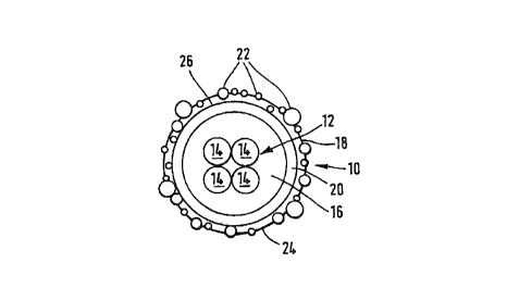
In order that the invention may be well understood, an
embodiment thereof which is given by way of example only will now
be described with reference to the accompanying drawing, in which
the single figure is a schematic cross-section of an optical fibre
assembly for blown installation.
The illustrated assembly 10 comprises a fibre unit 12
comprising a plurality of coated optical fibres 14. The
illustrated unit 12 comprises four coated optical fibres, but it
is to be understood that it may comprise a number of fibres other
than four, for example eight, or only one fibre.
Each coated fibre 14 is provided with primary and secondary
coatings as is conventional and the coated fibres are disposed
with their secondary coatings touching. The fibre unit 12 is
provided with a coating comprising an inner layer 16, an external
layer 18 and an intermediate layer 20. Each layer comprises a
radiation-cured polymer. The inner layer comprises a material


_ -3-

A '~

21 33356

having a lower modulus of elasticity than that of the external
layer and forms a soft buffer layer for the fibre unit. The
external layer is harder and more robust than the buffer layer and
functions to protect the buffer layer and fibre unit. The
external layer 18 contains particulate material in the form of
hollow glass beads 22, some of which project from the outer
surface 24 of the external layer 18. It will also be noted that
some of the beads are disposed adjacent the inner surface 26 of
the external layer 18. It is this disposition of the beads which
is considered in EP-A-0521710 to initiate the formation of cracks
during bending of the assembly. It is also believed that cracks
in the external layer may be initiated from the outer surface
thereof. The intermediate layer is provided to arrest the
propagation of cracks in the external layer towards the inner
buffer layer and may be formed of the same material as the
material of the external layer, but does not contain any beads 22.
In this case the modulus of elasticity of the material of the
intermediate layer is the same as that of the external layer.
However, it is to be understood that it may be formed of another
material but the modulus of elasticity, and/or the thickness, of
the intermediate layer is selected to enable the assembly to have
a desired overall stiffness.
In the illustrated embodiment the outside diameter of the
inner layer is 800Amm, the outside diameter of the intermediate
layer is 850Amm and the outside diameter of the external layer is
910Amm. The average diameter of the beads contained in the
external layer is 35Amm, and accordingly with close tolerances on


A

21 333s6

the layer and bead diameters the required amount of bead
projection from the outer surface of the external layer for good
blowability is provided.
In the disclosed embodiment, the materials forming the layers
s are W curable multi-functional acrylates. Specifically the
material forming the inner layer is Cablelite 3287-9-37, the
material forming the intermediate layer is Cablelite 950-705 or
Zeneca NEP 87 and the external layer which contains the beads is
formed from Zeneca NEP 86. Cablelite and Zeneca are trade names
of DSM Desotech BV and Zeneca, respectively.
As will be appreciated from the above, the requirement of
bead projection from the outer surface of the external layer is
incompatible with the requirement for there to be an absence of
beads adjacent the inner surface of the external layer in the
method disclosed in EP-A-0345968. Unless the bead diameter is
greater than the thickness of the external layer, in which case
beads will be positioned adjacent the inner surface, bead
projection cannot be guaranteed. If the diameter of the beads is
less than the thickness of the external layer neither bead
projection from the outer surface nor absence of beads adjacent
the inner surface can be guaranteed. In fact, in these
circumstances the situation is aggravated because the beads sink
in the material of the external layer as it is applied in liquid
form. The use of an intermediate crack arresting layer avoids the
problems associated with the location of the beads adjacent the
inner surface and allows the use of beads with a greater diameter
than the thickness of the external layer.


A~

21 33356
Additionally, the use of an intermediate layer provides a
means by which the overall stiffness of the optical fibre assembly
may be adjusted to a value which provides good blow
characteristics, since the thickness and modulus of elasticity of
the intermediate layer are both variables which can alter this
overall stiffness.


A

Representative Drawing
A single figure which represents the drawing illustrating the invention.
Administrative Status

For a clearer understanding of the status of the application/patent presented on this page, the site Disclaimer , as well as the definitions for Patent , Administrative Status , Maintenance Fee  and Payment History  should be consulted.

Administrative Status

Title Date
Forecasted Issue Date 1997-12-16
(22) Filed 1994-09-30
(41) Open to Public Inspection 1995-04-02
Examination Requested 1996-12-09
(45) Issued 1997-12-16
Deemed Expired 2009-09-30

Abandonment History

There is no abandonment history.

Payment History

Fee Type Anniversary Year Due Date Amount Paid Paid Date
Application Fee $0.00 1994-09-30
Registration of a document - section 124 $0.00 1995-06-29
Maintenance Fee - Application - New Act 2 1996-09-30 $100.00 1996-08-19
Request for Examination $400.00 1996-12-09
Final Fee $300.00 1997-08-19
Maintenance Fee - Application - New Act 3 1997-09-30 $100.00 1997-09-11
Maintenance Fee - Patent - New Act 4 1998-09-30 $100.00 1998-09-10
Maintenance Fee - Patent - New Act 5 1999-09-30 $150.00 1999-09-02
Maintenance Fee - Patent - New Act 6 2000-10-02 $150.00 2000-09-05
Maintenance Fee - Patent - New Act 7 2001-10-01 $150.00 2001-08-31
Maintenance Fee - Patent - New Act 8 2002-09-30 $150.00 2002-09-03
Maintenance Fee - Patent - New Act 9 2003-09-30 $150.00 2003-09-03
Maintenance Fee - Patent - New Act 10 2004-09-30 $250.00 2004-09-01
Maintenance Fee - Patent - New Act 11 2005-09-30 $250.00 2005-09-01
Maintenance Fee - Patent - New Act 12 2006-10-02 $250.00 2006-08-30
Maintenance Fee - Patent - New Act 13 2007-10-01 $250.00 2007-08-31
Owners on Record

Note: Records showing the ownership history in alphabetical order.

Current Owners on Record
PIRELLI GENERAL PLC
Past Owners on Record
PRESTON, ROGER STEPHEN
SMITH, DAVID BRIAN
Past Owners that do not appear in the "Owners on Record" listing will appear in other documentation within the application.
Documents

To view selected files, please enter reCAPTCHA code :


To view images, click a link in the Document Description column. To download the documents, select one or more checkboxes in the first column and then click the "Download Selected in PDF format (Zip Archive)" or the "Download Selected as Single PDF" button.

List of published and non-published patent-specific documents on the CPD .

If you have any difficulty accessing content, you can call the Client Service Centre at 1-866-997-1936 or send them an e-mail at CIPO Client Service Centre.


Document
Description 
Date
(yyyy-mm-dd) 
Number of pages   Size of Image (KB) 
Cover Page 1997-12-12 1 40
Cover Page 1995-10-22 1 83
Abstract 1995-10-22 1 46
Claims 1995-10-22 2 121
Drawings 1995-10-22 1 49
Description 1995-10-22 6 349
Drawings 1997-04-22 1 9
Claims 1997-04-22 3 105
Abstract 1997-04-22 1 14
Description 1997-04-22 6 221
Representative Drawing 1997-12-12 1 6
Correspondence Related to Formalities 1997-08-19 1 51
Prosecution Correspondence 1996-12-09 1 48
Prosecution Correspondence 1995-01-10 1 41
Prosecution Correspondence 1994-09-30 16 573
Fees 1996-08-19 1 72