Note: Descriptions are shown in the official language in which they were submitted.
":
zi33~s8
EXPRESS MAIL N0. IB59787871X
METHOD AND APPARATUS FOR BENDING TUBES USING SPLIT BEND DIE
Background of the Invention
The field of the invention generally relates to a
method and apparatus for bending tubes such as for making
heat exchangers, and more particularly relates to a split
bend die and method of rotating the split sections of the
bend die after bending a tube to reduce bend angles and
vertical spacings between adjacent parallel segments of a
tubular heat exchanger.
As is well known, residential furnaces have been
constructed using tubular heat exchangers instead of the
more conventional clam-shell heat exchangers. With such
arrangement, a plurality of stainless steel or aluminized
steel tubes are arranged within a heat exchange chamber of a
furnace, and one end of each is fired by an individual
burner. The hot combustion gases pass through the tubes,
and heat is transferred to household return air that is
forced across outside surfaces of the tubes.
In the above-described furnace arrangement, it is
desirable to maximize the heat exchange surface area within
the confined or restricted volume inside the heat exchange
chamber. It may also be desirable to minimize the size, and
in particular, the height of the heat exchange chamber so
that the furnace can be used at installations that have
height restrictions. Accordingly, tubes have been bent into
1
~13~36g
serpentine configurations with parallel straight segments to
increase the length of tubes that will fit into a heat
exchange chamber. In particular, tubes have been rotated
between successive bends so that the parallel straight
segments are not linearly aligned. Thus, the bends can be
seen to zigzag back and forth when the parallel segments are
viewed from their ends. The zigzagging is desirable because
it promotes turbulence in household return air that is
forced across the outside surfaces of the tubes. Thus, heat
transfer is enhanced.
Another reason for zigzagging relates to the apparatus
used to bend the tubes. In particular, one apparatus is
described in U.S. Pat. No. 5,142,895. A tube is seated in
the groove of a rotary bend die, and a pressure die and
clamp die are moved up against the opposite side of the
tube. The bend die and the clamp die are then rotated
approximately 180° about a vertical axis while the pressure
die moves forward linearly carrying the tube tangentially to
the bend point. The clamp die and pressure die are then
retracted and returned to their respective initial
positions, and the tube is repositioned with respect to the
bend die so that another 180° bend can be made. The tube is
also rotated to elevate the just formed segment above the
path used by the clamp die on the next bend. This tube
rotation leads to segments that zigzag rather than being
2
CA 02133368 2004-09-22
77643-5
disposed in a single plane. The apparatus used a split bend
die wherein an upper section was elevated from a lower
section to remove the tube which had been formed with
controlled wrinkles past the 180° tangent point.
A later tube bending improvement was described in
U.S. Patent No. 5,284,041. After bending the tube, the
upper section of the bend die was independently rotated
through a 90° angle about a vertical axis different than the
bend die rotation axis. That is, after the upper and lower
sections were rotated together about a first vertical axis
to form a bend, the upper and lower sections of the bend die
were split and then the upper section was independently
rotated about a different axis. The independent rotation
caused a portion of the upper section to be displaced
laterally to vacate a region directly above the lower
section. Then, when the tube was rotated to form a zigzag
and/or moved forwardly to position for the next bend, a
portion of the tube was permitted to pass through the
vacated region. With such arrangement, the minimum bend
angle between successive bends was less restricted than
without rotating the upper section of the split bend die.
For example, without rotating the upper section of the split
bend die, the angle between successive bends or segments in
the zigzag configuration had
3
X133368
to be relatively large such as 108° to clear the upper
section of the bend die. However, by rotating the upper
section out of the way, smaller bend angles such as, for
example, 60° could be formed. As a result, heat exchanger
segments could be densely packed in a relatively low profile
furnace.
One drawback of the above described arrangement is that
a complicated mechanism using nonstandard designs or
practices is generally required to rotate the upper section
of the bend die independently. During a bending operation,
the upper and lower bend die sections are lacked together
and rotated about a first axis. It then becomes a
complicated mechanical task to lift the upper section and
rotate it about a second axis.
4
CA 02133368 2004-09-22
77643-5
Summary Of The Invention
It is an object of the invention to make
successive bends of a tube such as for a heat exchanger, and
to provide relatively small bend angles with relatively
small center line radii to arrange parallel segments of the
tube relatively close together in a zigzag pattern. By such
arrangement, the parallel segments can be densely packed
into a heat exchange chamber of restricted volume for
optimal heat transfer.
It is a further object to limit the complexity of
the bending equipment, and to use relatively conventional
and standard mechanisms. For example, it is an object to
avoid using an upper bend die that has a second axis of
rotation different than the rotational axis used for the
bending.
It is also an object to use a bend die that can be
split, but the upper and lower sections are always in
registration during bending and in preparing for a
subsequent bend.
According to one aspect the invention provides a
method of bending a tube comprising the steps of: seating
said tube tangentially in a tube groove of a bend die with a
first portion of the tube extending forward from the bend
die and a second portion extending rearward from the bend
die; clamping said tube to said bend die with a clamp die;
moving said tube tangentially toward said bend die with a
pressure die while rotating said bend die and said clamp die
to form a bend in said tube wherein said first portion
5
CA 02133368 2004-09-22
77643-5
extends rearwardly from said bend die substantially parallel
with said second portion of said tube in said bend die;
splitting upper and lower sections of said bend die along a
shaft; rotating said upper and lower bend die sections in
unison through a predetermined angle to position a
substantially straight end of said upper bend die
substantially parallel with said first portion of said tube;
providing relative motion between said tube and said bend
die to position said second portion of said tube adjacent
said shaft; rotating said tube about said second portion to
raise said first portion above said upper bend die section;
closing said bend die sections back together and rotating
said bend die back to its initial angular orientation; and
moving said tube relative to said bend die to position said
tube for a subsequent bend.
Simply viewed, the relative motion between the
split bend die and the tube positions the tube up against or
next to the shaft, and reduces spacing between parallel
segments that is required to clear the upper die section as
the tube is moved in preparation for a subsequent bend.
This process is mechanically simpler to implement than
rotating the upper die section about an axis other than the
rotational axis of the bend die to vacate a region above the
lower die section.
6
~1~3368
The result, however, is essentially the same in that
relatively small bend angles and vertical spacings between
parallel segments are achieved for dense packing of parallel
heat exchanger segments.
In addition to providing relative motion between the
tube and the split bend die sections, a number of other
features may preferably be used to further limit the
required spacing between parallel segments. For example,
the upper bend die section preferably has a truncated upper
portion along the substantially straight end; this feature
enables the parallel segments to be closer because the tube
can pass through the truncated portion as the tube is
rotated about the second portion. Another preferable
feature is that the sides of the bend die be of differerLt
lengths with the clamp die clamping the tube to the longer
side. In particular, the side facing the clamp die should
have a minimum length to properly mate with the clamp die,
and the opposite side should have a minimum length to
properly complete the bend. However, these two minimum
lengths are different with the clamp requirement generally
being longer. Therefore, by making each side only. so long
as generally required to perform its intended function, and
forming the straight end of the upper bend die section at
oblique angles to the sides, the straight end is made as
close to the center of rotation as possible. Simply stated,
7
CA 02133368 2004-09-22
77643-5
the bend die is made as short as possible to further limit
the parallel segment spacing that will clear the upper
section as the tube is rotated. Another feature is that the
shaft may comprise an indentation at the level to which the
second portion is moved to be adjacent to the shaft.
Therefore, the tube can be moved closer to the center of the
shaft.
It is also preferable that the method further
comprise a step of moving the tube forwardly before rotating
the tube about the second portion. Also, it is preferable
that the shaft extend through at least one of the bend die
sections, and that the shaft be keyed to the one section to
cause the shaft and the upper section to be rotated in
unison and in response to the lower section being rotated.
According to another aspect the invention provides
a method of bending a tube, comprising the steps of:
providing a bend die having opposing sides with respective
tube grooves and a bend-forming end with a curved tube
groove extending between the tube grooves of the opposing
sides to form a continuous tube groove adapted for receiving
a tube while a bend is being formed, the bend die comprising
upper and lower sections splitable along a shaft extending
up through at least one of the sections, the upper section
having a second end with an upper truncated portion;
providing a clamp die having a tube groove operative with
one of the opposing sides of the bend die to clamp the tube
in the tube groove of the one side in preparation for
bending the tube; rotating the bend die through a first
predetermined angle and moving the clamp die through a
corresponding arc to maintain clamping of the tube with the
8
CA 02133368 2004-09-22
77643-5
one side of the bend die as the bend die is rotated to bend
the tube; retracting the clamp die from the one side of the
bend die after the bend die has been rotated; rotating the
upper and lower sections through a second predetermined
angle less than the first predetermined angle to align the
second end of the upper section with a straight segment of
the tube on one side of the bend die; and rotating the tube
about a second straight segment of the tube on the side
opposite the one side of the bend die to pass the first
straight segment through the truncated portion of the upper
bend die as a step in positioning the tube in preparation
for a subsequent bending operation.
According to another aspect the invention provides
tube bending apparatus comprising: a bend die having
opposing sides and a bend-forming end extending between the
opposing sides, the bend-forming end and the opposing sides
having a continuous tube groove adapted for receiving a tube
while a bend is being formed; a clamp die having a tube
groove operative with one of the opposing sides of the bend
die to clamp the tube in the tube groove of the one side,
the clamp die being moveable through an arc to maintain
clamping of the tube with the one side of the bend die as
the bend die is rotated through a first predetermined angle
to bend the tube, the clamp die being retractable from the
one side of the bend die after rotation of the bend die; and
the bend die comprising upper and lower sections splitable
along a shaft extending through at least one of the
sections, the upper section having a second end with a
truncated upper portion wherein, after a bend has been
9
CA 02133368 2004-09-22
77643-5
formed, the upper and lower sections are split and rotated
through a second predetermined angle less than the first
predetermined angle to align the second end with a first
straight segment of the tube on one side of the bend die and
the tube is rotated about a second straight segment of the
tube on the opposite side of the bend die with t:he first
straight segment passing through the truncated portion of
the upper bend die in preparation for a subsequent bend.
According to yet another aspect the invention
provides tube bending apparatus comprising: a bend die
having opposing sides with respective tube grooves and a
bend-forming end with a curved tube groove extending between
the tube grooves of the opposing sides to form a continuous
tube groove adapted for receiving a tube while a bend is
being formed, the bend die comprising upper and lower
sections splitable along a shaft extending up through the
lower section; a clamp die having a tube groove operative
with one of the opposing sides of the bend die t:o clamp the
tube in the tube groove of the one side; means for rotating
the bend die through a first predetermined angle and moving
the clamp die through an arc to maintain clamping of the
tube with the one side of the bend die as the bend die is
rotated to bend the tube; means for retracting the clamp die
from the one side of the bend die after the bend die has
been rotated; means for rotating the upper and lower
sections in unison through a second predetermined angle less
than the first predetermined angle to align a second end of
the upper section with a straight segment of the tube on one
side of the bend die; means for providing relative movement
9a
CA 02133368 2004-09-22
77643-5
between the tube and the upper and lower sections of the
bend die when the upper and lower sections are split to
position the second segment of the tube adjacent to the
shaft; and means for rotating the tube about a second
straight segment of the tube on the opposite side of the
bend die to move the tube to a position in preparation for a
subsequent bending operation.
9b
X133368
Brief Description of the Drawings
The foregoing objects and advantages will be more fully
understood by reading the following Description of the
Preferred Embodiment with reference to the drawings wherein:
FIG. 1 is a perspective view of tube bending equipment
in accordance with the invention;
FIG. 2 is a perspective view of a tube positioned in
the equipment of FIG. 1 at the commencement of a bending
operation;
FIG. 3 is a perspective view of the equipment of FIG. 2
at an intenaediate stage of bending;
FIG. 4 is a perspective view of the equipment of FIG. 2
after completion of a bending operation and before the tube
is repositioned for a subsequent bending operation of the
tube;
FIG. 5 is a partially sectioned front view of the bend
die, clamp die and pressure die after completion of a bend;
FIG. 6 is a top view of the bend die after retraction
of the clamp die and pressure die after completion of a
bend;
FIG. 7 is a partially sectioned front view of. the bend
die after being split;
FIG. 8 is a top view after the tube has been moved
forward and the bend die has been rotated through a
predetermined angle A; and
2133368
FIG. 9 is a front view of the split bend die with the
tube positioned in accordance with the invention for
rotation about an input segment.
11
~13336~
Descri~t~ion of the Preferred Embodimen
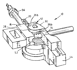
Referring-to FIG.1, tube bending tooling 10 includes
bend die 12, clamp die 14, pressure die 16, plastic plug
mandrel 18 and plastic follower 20. As will be described in
detail later herein, bend die 12 is a split die having
upper and lower sections 22a and b which, as shown in FIG.
7, can be vertically separated at a mid portion 24. Also
referring to FIGS. 5-9, bend die 12 has two opposing sides
26a and b, a bend forming end 28, and a substantially
straight back end 30. Opposing sides 26a and b and bend
forming end 28 have a continuous horizontal tube groove 32
that has generally elliptical curvature and is adapted for
receiving a tube 34 of predetermined diameter such as 1.25
inches and predetermined wall thickness such as 0.035 inches~
as a bend is being formed. Bend forming end 28 is rounded
and slightly larger than a semicircle, and opposing side 26a
is straight and substantially tangent thereto. Side 26a
functions as a grip section with clamp die 14, and therefore
has a minimum suitable length such as o.833 inches for
0 performing this function. For reasons to be described in
detail in accordance with the invention, side 26a of the
upper section 22a is made as short as suitably possible,
while the corresponding side 26a of the lower section 22b is
preferably longer. The second opposing side 26b is also
5 straight and tangent to bend-forming end 28. Because bend-
12
~13~36~
forming end 28 is slightly greater than a semicircle, side
26b is angled inwardly such as by 7° from parallel with side
26a to provide an overbend to compensate for springback.
Thus, after a bend has been formed in a manner to be
described, output and input straight segments 62a and b of
tube 34 are substantially parallel as desired. Side 26b
generally has a minimum length such as 0.473 inches to
properly complete a bend. For reasons to be described in
detail in accordance with the invention, side 26a of the
upper section 22b is made as short a suitably possible,
while the corresponding side 26b of the lower section 22b is
preferably longer. As has been described, side 26a of upper
die section 22a is longer than side 26b because side 26a
performs the function of gripping the tube 34 with clamp. die
14. Thus, as shown best in FIGS. 6 and 8, back end 30 is
oblique to sides 26a and b, and has a minimum spacing to the
axis of rotation 38 of bend die 12. Still referring to FIG.
9, upper bend die section 22a has a truncated upper portion
40 along back end 30. Tube groove 32 here has a plurality
of vertically elongated controlled-wrinkle indentations 42
or serrations that are disposed in an arc greater than 180°.
Bend die 12 is mounted to a conventional rotary arm 44
such that bend die 12 can be rotated during a bending
operation. In particular, as shown best in FIG. 5, a keyed
shaft 46 such as a square shaft 46 passing up through a
13
~1~~36~
corresponding square bore 48 is securely affixed to upper
bend die section 22a. Thus, as lower section 22b is rotated
with rotary drive arm 44, upper section 22a is
correspondingly driven by shaft 46.
Clamp die 14 and pressure die 16 have respective linear
tube grooves 50 and 52 (FIG. 3) that may preferably be
elliptically shaped and adapted to receive a tube 34.
Initially, pressure die 16 and clamp die 14 are lined side
by side with tube grooves 50 and 52 linearly aligned, and
they are spaced from the axis defined by side 26a as shown
in FIG. 1. A plastic follower 20 having an arcuate surface
generally conforming to the outer diameter of the tube 34
being bent is mounted behind the bend die 12 diametrically
opposite pressure die 16. A mandrel rod 54 with a plastic
plug mandrel 18 on the end extends forwardly with bend die .
12 and plastic follower 20 on one side, and pressure die 16
and clamp die 14 on the opposite side. Supporting and drive
mechanisms for bend die 12, pressure die 16, clamp die 14,
mandrel rod 54 and plastic follower 20 are not described in
detail herein because they are conventional, and an
explanation of them is not necessary for an understanding of
the invention.
Referring to FIG. 2, the first step in a bending
operation is to insert tube 34 onto mandrel rod 54. Tube 34
is held in place there by collet 56. Pressure die 16 and
14
~13336~
clamp die 14 are then moved laterally to engage tube 34 as
shown. In particular, clamp die 14 is moved diametrically
opposite side 26a of bend die 12 and mates therewith. The
mating portion 58 of clamp die 14 may be unconventionally
short because, as described earlier, the corresponding side
26a of upper bend die 12 has a minimum length such as, for
example, 0.833 inches. Clamp die 14 and the grip section of
side 26a are interlocked, and tube 34 is firmly clamped
therebetween. In FIG. 5, face edges of clamp die 14 can be
seen to seat in mating channels of bend die 12.
Alternately, face portions of clamp die 14 and bend die 12
can be mated or interlocked using a tongue and groove
arrangement to reduce the profile of bend die 12. As will
be apparent later herein, a bend die of lower profile
enables the use of smaller angles between consecutive bends.
Similarly, the portion of tube 34 immediately behind clamp
die 14 is received in tube groove 52 of pressure die 16.
Lateral pressure exerted on tube 34 by pressure die 16 is
restrained by plastic follower 20.
Referring to FIG. 3, bend die 12 and clamp die 14 are
rotated in unison while pressure die 16 drives linearly
forward. Tube 34, which remains held by collet 56, is
driven forwardly to the tangent or bend point of die 12.
Plastic follower 20 has a relatively low coefficient of
friction such that tube 34 readily slides over it while
zm33s~
plastic follower 20 continues to restrain the gressure of
pressure die 16. During a bending operation, tube 34
continues to be clamped between clamp die 14 and die side
26a as clamp die 14 is driven through a corresponding arc by
a suitable rotating arm 44. As tube 34 bends around
rotating bend die 12, the inside of the tube bend is
compressed and the metal flows into the elongated vertical
serrations 42 thereby forming controlled-wrinkles 60 as
shown in FIG. 8.
Referring to FIG. 4, tube 34 is shown after it has been
bent a full 180° such that straight output segment 62a is
substantially parallel with a straight input segment 62b
extending from collet 56. Actually, bend die 12 is rotated
slightly more than 180° such that segment 62a and b will be
substantially parallel when they spring back. In such
state, bend die 12 has rotated approximately 180° from the
initial angular orientation, and likewise clamp die 14 has
moved through an approximate 180°arc about the central axis
of rotation 38 such that tube groove 50 now faces in the
opposite direction from the initial orientation, and still
clamps tube 34 to side 26a of bend die 12. Also, pressure
die 16 is shown to have linearly traversed to its forward-
most position where it still engages tube 34 at its tangent
point to bend die 12. During the entire bending operation,
plastic plug mandrel 18 remains in a stationary position
16
X133368
within tube 34, and thereby functions to limit or control
the collapse of tube 34. More specifically, plastic plug
mandrel 18 does not advance around the bend as a multiple
ball mandrel would, but rather remains stationary with its
tip being in the approximate region of the tangent or bend
point. Plastic mandrel 18 is subject to wear that
particularly occurs on the outside as the wall of tube 34
slides against it, but plastic plug mandrels 18 are
relatively inexpensive to replace. As the plastic wears,
the plastic plug mandrel 18 is moved slightly forward by a
simple adjustment so that the tip remains properly
positioned to control collapse to the desired degree. In an
alternate embodiment, tubes 34 may be bent without using a
plastic plug mandrel 18 or any other internal supporting
structure. In other words, tubes 34 can be bent without any
collapse suppressing structure on the inside. Also, tubes
34 can be bent without a bend die 12 having elongated
serrations 42 to provide controlled-wrinkles 60. This
concludes the description of a single bending operation.
Referring to FIG. 5, a partially sectioned view shows
bend die 12 at the completion of a bending operation. In
particular, pressure die 16 is shown at the left or input
side and clamping die 14 is shown at the right or output
side of bend die 12. As shown, shaft 46 extends through
bore 48 in the lower section 22b and is secured to the upper
17
~13336~
section 22a. More specifically, upper section 22a has a
bore 64 with a annular ring 66 or ledge, and a fastening
member 68 with a head 70 passes down through bore 64 and is
secured into the top of shaft 46. The head 70 seats against
the annular ring 66 to securely affix upper section 22a to
shaft 46. The shaft 46 below ring 66 is keyed to bore 64 to
provide registration between upper and lower sections 22a
and b.
Referring to FIG. 6 and 7, top and partially sectioned
front views of bend die 12 are shown after bend die 12 has
been split into upper and lower sections Z2a and b. As
shown here, collet 56 holds tube 34 at its present level
after bending, and upper section 22a is raised by elevating
shaft 46 using a suitable mechanism. Further, lower section'
22b is lowered into a keyway 72 of rotary arm 44 as shown in
FIG. 1 to position tube 34 substantially at a mid-level
between upper and lower sections 22a and b. A shoulder 76
of shaft 46 contacts a lip 78 of bore 48 to insure precise
alignment. 'Such action may be implemented using a suitable
mechanism (not shown) such as a double action cylinder
wherein the plunger or shaft 46 is raised while the outer
cylinder or-lower section 22b is lowered. Alternatively,
lower section 22b or upper section 22a could be held
stationary while the other section 22a or b is separated or
split therefrom, and then tube 34 could be moved vertically
18
m3~3ss
by collet 56 to a mid-level therebetween. For reasons to be
described subsequently, the under surface of upper section
22a is spaced from the top surface of lower section 22b by a
distance larger than the outer diameter of tube 34. For
example, when the outer diameter of tube 34 is, for example,
1.25 inches, upper and lower sections 22a and b may
preferably be split or separated by 1.38 inches.
The next steps in preparing for a subsequent bend of
tube 34 is for collet 56 to move tube 34 forwardly as shown
in FIG. 8 and laterally as shown in FIG. 9. The forward
motion of tube 34 moves tube 34 out of tube groove 32 so
that straight output segment 62a of tube 34 may be rotated
up and over upper section 22a in a manner to be~described.
Alternate to moving tube 34 laterally as shown in FIG. 9',
the split sections 22a and b of bend die 12 may be moved
laterally to tube 34. The important function is that there
be relative motion between tube 34 and sections 22a and b of
split bend die 12 to position the input straight segment 62b
of tube 34 adjacent or next to shaft 46 so that the input
straight segment 62b can be as close as possible to the
output straight segment 62a and still have the output
segment 62a clear the upper section 22a as tube 34 is
rotated about input segment 62b in a manner to be described.
As described earlier herein, shaft 46 is square to key shaft
46 to upper section 22a and lower section 22b. However,
19
~13336~
indentation portion 74 is located at the height of tube
segment 62b which here is the mid-level between upper and
lower sections 22a and b as shown in FIG. 9. Indentation
portion 74 is here circular with upper and lower transition
regions from square to circular and visa versa, respectively
By such arrangement, input straight segment 62b is
positioned closer to the center of shaft 46 to further
reduce the required spacing between input straight segment
62b and output straight segment 62a that will clear upper
section 22a as tube 34 is rotated about input segment 62b.
Referring to FIG. 8, the next step in preparing to make
a subsequent bend is rotating upper section 22a, as well as
lower section 22b which for simplicity is not shown in
FIG.8, through a predetermined angle A about the axis of
rotation 38 of bend die 12 to position the straight back end
30 of the upper section 22a substantially parallel to the
output straight segment 62a of tube 34. As described
earlier, straight back end 30 is oblique to sides 26a and b,
so angle A would typically be other than 90°. In
particular, angle A would typically be in the range from
100° to 120° depending on the parameters of upper section
22a, and rotation would be counter to the bending direction.
Referring to FIG. 9, the next step in positioning tube
34 for a subsequent bend is to rotate the collet 56 to
rotate tube 34 about the axis of the straight input straight
~13336~
segment 62b to raise the output segment 62a above upper
section 22a of bend die 12. As output segment 62a is
raised by rotation of tube 34 about input segment 62b,
output segment 62a passes through the truncated portion 40.
In particular, the envelope 80 in moving segment 62a to
position 62a' is shown passing through truncated portion 40.
In such manner, the required spacing between input segment
62b and output segment 62a is further reduced by cutting off
or truncating an upper portion 40 of upper section 22a. In
a preferred embodiment, truncated portion 40 is angled at
15° from vertical. By such arrangement, a tube with an
outer diameter of 1.25 inches may be bent with a center line
radius of 1.5 inches, and the bend angles B between adjacent
straight segments, here shown as segments 62b, 62a', 62d,
and 62d, may typically be in the range from 48° to 60°.
In summary, the upper bend die section 22a is made
relatively short, and after splitting the bend die 12, is
rotated in unison with the lower bend die section 22b until
the back end 30 of the upper section 22a is substantially
parallel with the straight segment 62a of the tube 34 at the
output side of the bend die 12. Relative motion is provided
to position the straight segment 62b at the input side of
the bend die 12 adjacent or next to shaft 46. By such
action, input and output sections 62a and b can be made
closer together and still have output segment 62a clear
21
~1~~36~
upper section 22a as tube 34 is rotated about input segment
62b. Some combination of a plurality of other features may
be combined to further reduce the center line radius or
spacing between two consecutive segments identified as input
segment 62b and output segment 62a as shown best in FIG. 9.
First, even though shaft 46 is keyed to cause rotation of
bend die sections 22a and b in unison and thereby simplify
the rotating mechanisms, shaft 46 has an indentation portion
74 to locate the input segment 62b closer to the center of
shaft 46. Second, upper section 22a is made relatively
short from bend-forming end 28 to the back end 30. More
particularly, the distance from the center axis 38 of
rotation of shaft 46 to back end 30 is minimized. Side 26a
has to be relatively long to provide clamping with clamp die
14, but side 26b can be made relatively short while having
enough length to complete a bend. Thus, back end 30 is
angled to be as close as possible to the center of shaft 46
while still enabling the required functions to be performed.
Finally, the upper portion 40 along the upper edge of back
end 30 is truncated. By combining these described features,
a radius of 2.375 can be provided between the center of
input segment 62b and output segment 62a to clear upper
section 22a with a tube having a diameter of 1.25 inches.
To complete the steps in preparation for making another
bend, collet 56 moves tube 34 out from in-between upper and
22
~~~~~b$
lower sections 22a and b, and moves tube 30 forwardly to
position the next desired bend location of tube 34 adjacent
to bend die 12. As can be seen from FIG. 9, if one or more
bends had previously been made in a process to form a
serpentine heat exchanger with zigzag parallel segments 62b,
62a', 62c, and 62d, the segments and bends would clear bend
die 12. The final steps are to close bend die sections 22a
and b back together and rotate bend die 12 back to its
initial angular orientation as shown in FIG. 1. Clamp die
14 and pressure die 16 are also repositioned in their
respective initial locations in preparation for making
another bend.
With the bending apparatus and method described
heretofore, relatively tight bends such as bends having ~
center line radius with 1.25 inch tube 34 can be made using.
relatively standard tube bending equipment. For example,
other than positioning and rotating the tube 34 using collet
56, the only nonstandard equipment is a mechanism to lift
shaft 46 to raise upper section 22a while lowering lower
section 22b. The rotation of upper and lower sections 22a
and 22b to the angular orientation as shown in FIG. 8 is
accomplished merely by programming rotary arm 44 to stop
momentarily after rotation back through predetermined angle
A. The apparatus and method simplified the prior art
23
~133~e~
actuation mechanism by eliminating the need to rotate the
upper section 22a independent of upper section 22b.
This completes the Description of the Preferred
Embodiment. A reading of it by those skilled in the art
will bring to mend many alterations and modification that do
not depart from the spirit and scope of the invention.
Therefore, it is intended that the scope of the invention be
limited only by the appended claims.
24