Language selection

Search

Patent 2133510 Summary

Third-party information liability

Some of the information on this Web page has been provided by external sources. The Government of Canada is not responsible for the accuracy, reliability or currency of the information supplied by external sources. Users wishing to rely upon this information should consult directly with the source of the information. Content provided by external sources is not subject to official languages, privacy and accessibility requirements.

Claims and Abstract availability

Any discrepancies in the text and image of the Claims and Abstract are due to differing posting times. Text of the Claims and Abstract are posted:

  • At the time the application is open to public inspection;
  • At the time of issue of the patent (grant).
(12) Patent Application: (11) CA 2133510
(54) English Title: ELECTRODELESS FLUORESCENT LAMP WITH OPTIMIZED AMALGAM POSITIONING
(54) French Title: LAMPE FLUORESCENTE SANS ELECTRODE AVEC MISE EN PLACE OPTIMISEE D'UN AMALGAME
Status: Deemed Abandoned and Beyond the Period of Reinstatement - Pending Response to Notice of Disregarded Communication
Bibliographic Data
(51) International Patent Classification (IPC):
  • H01J 65/00 (2006.01)
  • H01J 7/22 (2006.01)
  • H01J 9/00 (2006.01)
  • H01J 9/38 (2006.01)
  • H01J 9/395 (2006.01)
  • H01J 61/24 (2006.01)
  • H01J 61/28 (2006.01)
  • H01J 61/30 (2006.01)
  • H01J 61/42 (2006.01)
  • H01J 65/04 (2006.01)
(72) Inventors :
  • BOROWIEC, JOSEPH CHRISTOPHER (United States of America)
  • CHANG, HSUEH-RONG (United States of America)
  • SENECAL, ROBERT ARTHUR (United States of America)
(73) Owners :
  • GENERAL ELECTRIC COMPANY
(71) Applicants :
  • GENERAL ELECTRIC COMPANY (United States of America)
(74) Agent: CRAIG WILSON AND COMPANY
(74) Associate agent:
(45) Issued:
(22) Filed Date: 1994-10-03
(41) Open to Public Inspection: 1995-04-05
Availability of licence: N/A
Dedicated to the Public: N/A
(25) Language of filing: English

Patent Cooperation Treaty (PCT): No

(30) Application Priority Data:
Application No. Country/Territory Date
08/130,935 (United States of America) 1993-10-04

Abstracts

English Abstract


ELECTRODELESS FLUORESCENT LAMP
WITH OPTIMIZED AMALGAM
POSITIONING
Abstract
An amalgam is accurately placed and
retained in an optimal location near the cold spot of
an electrodeless SEF lamp for operation at a mercury
vapor pressure in the optimum range from approximately
four to seven millitorr. The amalgam is positioned at
the tip of an extended exhaust tube near the apex of
the lamp envelope by forming an indentation in the
exhaust tube and, in some embodiments, a dose locating
member in combination therewith. An evacuation hole
is formed below the indentation for evacuation of the
lamp envelope, or bulb, during lamp fabrication. In
an alternative embodiment, the extension of the
exhaust tube is situated perpendicular to the main
portion of the tube to allow for lateral adjustment of
the position of the amalgam, thereby allowing for even
further control of the amalgam operating temperature.


Claims

Note: Claims are shown in the official language in which they were submitted.


- 8 -
CLAIMS:
1. A method for manufacturing a solenoidal electric field (SEF)
fluorescent discharge lamp, comprising the steps of:
providing a light-transmissive envelope having an interior
phosphor coating for emitting visible radiation when excited by ultraviolet
radiation, said envelops having an apex portion, said envelope further
having a re-entrant cavity formed therein for containing an excitation coil,
said re-entrant cavity having an exhaust tube with an extension toward said
apex portion of said envelope, said extension having a tip;
inserting an amalgam into said exhaust tube and maintaining
said amalgam substantially at said tip of said extension thereof;
forming an indentation in said exhaust tube at a predetermined
location between said re-entrant cavity and said tip of said extension of said
exhaust tube;
forming an evacuation hole in said exhaust tube between said
indentation and said re-entrant cavity; and
evacuating and filling said envelope through said exhaust tube.
2. The method of claim 1, wherein said predetermined location is
such that mercury vapor pressure within said envelope is maintained within
the range from approximately four to seven millitorr during lamp operation.
3. The method of claim 1, further comprising the step of inserting
a dose locating member into said exhaust tube after inserting said amalgam
and before forming said indentation.

- 9 -
4. The method of claim 3, wherein said dose locating member
comprises a glass ball.
5. The method of claim 1, wherein said amalgam is selected from
the group consisting of: indium; a combination of bismuth and indium; a
combination of lead, bismuth and tin; zinc; and a combination of zinc,
indium and tin.
6. The method of any one of claims 1 to 5, wherein said extension
is situated perpendicular to said exhaust tube and said re-entrant cavity.
7. A solenoidal electric field (SEF) fluorescent discharge lamp,
comprising:
a light-transmissive envelope containing an ionizable, gaseous
fill for sustaining an arc discharge when subjected to a radio frequency
magnetic field and for emitting ultraviolet radiation as a result thereof, said
envelope having an interior phosphor coating for emitting visible radiation
when excited by said ultraviolet radiation, said envelope having an apex
portion, said envelope further having a re-entrant cavity formed therein;
an excitation contained within said re-entrant cavity for
providing said radio frequency magnetic field when excited by a radio
frequency power supply;
an exhaust tube having an extension extending through said re-
entrant cavity and toward said apex portion of said envelope, said exhaust
tube having a tip;
an indentation in said exhaust tube at a predetermined location
between said re-entrant cavity and said tip of said extension of said exhaust
tube;
an amalgam situated within said exhaust tube and maintained
in position substantially at said tip of said extension by said indentation.

- 10-
8. The SEF lamp of claim 7, wherein said predetermined location
is such that mercury vapor pressure within said envelope is maintained
within the range from approximately four to seven millitorr during lamp
operation.
9. The SEF lamp of claim 7, further comprising a dose locating
member for operating in combination with said indentation to maintain said
amalgam in position in said exhaust tube.
10. The SEF lamp of claim 9, wherein said dose locating member
comprises a glass ball.
11. The SEF lamp of claim 7, wherein said amalgam is selected
from the group consisting of: indium; a combination of bismuth and indium;
a combination of lead, bismuth and tin; zinc; and a combination of zinc,
indium and tin.
12. A solenoidal electric field (SEF) fluorescent discharge lamp
according to any one of claims 7 to 11, wherein said extension is situated
perpendicular to said exhaust tube and said re-entrant cavity.

Description

Note: Descriptions are shown in the official language in which they were submitted.


RD 22894
,~,
: " :
- 1- 21~3510 ~
ELECTRODELESS FLUORESCENT LA~
~ITH OPTIMIZED AMALGAM
. - ..
Field of the Invention
- ,:: :
:: 5 The present invention relates generally to
; ~ - . . ~.:- . ~
~ : fluorescent lamps and, more particularly, to accurate
. .
placement and retention of an amalgam in a solenoidal
: electric field~fluorescent discharge la~p for
optimally control~llng~mercury vapor pressure therein,
which amalgam placement~ and retention do not interfere
wi~h lamp proces~sing and~furthermore are maintained~
during lamp~operat~ion, regardless of lamp orientation. ~ ~-
' _ ~; ,:,
; The~optimum~merc~ury~vapor pressure for
:15 production of ~ 253?~A~ radiation to exoite a phosphar
coating in a fluorescent lamp is approximately six
millitorr, correspondi~ng to a mercury reservoir~ .
temperature of approximately 40 C. Conventional ~-
tubular fluorescent lamps operate at a power density : ~:~
2~ (i.e,, typically measured as power input per phosphor
area) and in a fixture configured to ensure operation
of the lamp at or about a mercury vapor pressure of
six milli~orr (typically in a range from approximately

RD 22894
~33~0
-- 2
four to seven millitorr); that is, the lamp and
fixture are designed such that the coolest location
~i.e., cold spot) of the fluorescent lamp is
approximately 40 C. Compact fluorescent lamps,
however, including electrodeless solenoidal electric
field (SEF) fluorescent discharge lamps, operate at
higher power densities with the cold spot temperature
typically exceeding 50 C. As a result, the mercury
vapor pressure is higher than the optimum four to
seven millitorr range, and the luminous output of the
lamp is decreased.
One approach to controlling the mercury
vapor pressure in an SEF lamp is to use an alloy
capable of absorbing mercury from its gaseous phase in
varying amounts, depending upon temperature
conditions. Alloys capable of forming amalgams with
mercury have been found to be particularly useful.
The mercury vapor pressure of such an amalgam at a
given temperature is lower than the mercury vapor
pressure of pure liquid mercury.
Unfortunately, accurate placement and
retention of an amalgam to achieve a mercury vapor
pressure in the optimum range in an SEF lamp are
difficult. For stable long-~erm operation, the
amalgam should be pl~ced and retained in a relatively
cool location with minimal tempera~ure variation.
Such optimal locations are at or near the tip, or ~ -
apex, of the lamp envelope, or crown. Accordingly, it
is desirable to place the amalgam in an optimal
position n~ar the cold spot of the lamp. Moreover, to
achieve the desired beneficial effects of an amalgam
in an SEF lamp, the amalgam should maintain its
composition and optimized location during lamp

RD 22894
`: ~`
.,..
~1335~0
-- 3 --
processing and manufacturing steps as well as during
lamp operation.
Summa~y_of the Invention
An amalgam is accurately placed and
5 retained in an optimal location near the cold spot of ~- ~
an electrodeless SEF lamp for operation at a mercury `
vapor pressure in the optimal range from approximately
four to seven millitorr. The amalgam is positioned at
the tip of an exhaust tube extension near the apex of ` ~ -
the lamp envelope by forming an indentation therein
and, in some embodiments, using a dose locating member ~-
in combination with the indentation. An evacuation
hole is formed below the indentation for evacuation of
:: :
~ the lamp envelope,;or bulb, during lamp fabrication.
~ .
In an alternative embodiment, the exhaust
tube extension is situated perpendicular to the main
portion of the tube to aIlow for lateraI adjustment of
~ the position of the amalgam, thereby allowlng for even
-~ further control oS the amalgam operating temperature~
.: .
The features~and advantages of the present
invention will become apparent from the ~ollowing
-~ detailed description of the invention ~hen read with
the accompanying drawings in which:
Figure 1 illustrates, in partlal cross
section, a typical electrodeless S~F fluorescent
discharge lamp;
Figure 2 illus~rates, in partial cross `
section, an electrodeless SEF fluorescent discharge

RD 22894
S 1 0
lamp aecording to one embodiment of the present
invention; and
Figure 3 illustrates, in partial cross
section, an electrodeless SEF fluorescen~ discharge
lamp according to an alternative embodiment of the
present invention.
~etailed DescriDtion of th~
I~vention
Figure 1 illustrates a typical
electrodeless SEF fluorescent discharge lamp 10 having
an envelope 12 containing an ionizable gaseous fill.
A suitable fill, for example, comprises a mixture of a
rare gas ~e.g., krypton and/or argon) and mercury
vapor and/or cadmium vapor. An excitation coil 14 is
situated within, and removable from, a re-entrant
cavity 15 within envelope 12. For purposes of
illustration, coil 14 is shown schematically as being
wound about an exhaust tube 20 which is used for
filling the lamp. ~owever, the coil may be spaced
apart from the exhaust tube and ~ound about a core of
insulating material or may be free standing, as
desired. The interior surfaces of envelope 12 are
coated in well-known manner with a suitable phosphor
18. Envelope 12 fits into one end of a base assembly
17 containing a radio frequency power supply (not
shown) with a standard (e.g., Edison type~ lamp base
19 at the other end. Envelope 12 is shown in Figure 1
in a "crown-up", or "base-down", position.
In operation, current flows in coil 14 as a
result of excitatlon by a radio frequency power supply
(not shown). As a result, a radio frequency magnetic
field is established wi~hin envelope 12 which ionizes

~D 22894
.... .
.. .. .
_ 5 _ 2 1 3 ~ S ~ O
and excites the gaseous fill contained therein,
resulting in an ultraviolet discharge 23. Phosphor 18:
absorbs the ultraviolet radiation and emits visible ~ -
radiation as a consequence thereof. -
In accordance with the present invention, a
properly constituted amalgam is accurately placed and
retained in an optimal location in an SEF lamp for
operation at a mercury vapor pressure in the optimum -
range from approximately four to seven millitorr,~
which amalgam maintains its composition and location
during lamp processing as well as during lamp `
operation, regardless of lamp orientation. In ~-
particular, the amaIgam is~accurately positioned and
retained at a relatively cool location with minimal
temperature variation near the apex of the lamp
envelope. The apex of~the lamp envelope typically
comprises the cold spot of the lamp.
An exemplary amalgam comprises a
combination of bismuth~and indium. Another exemplary
amalgam comprlses pure indium. Still another
exemplary amalgam~comprises;a combination of lead,
bismuth and tin,~such as described in commonly
; assigned V.S. Pat~. No. i,262,231 of;J.M. Anderson and
P.D. Johnson, issued April 14, 19~1, which is
;~ 25 incorporated by refe~rence~herein. Yet~another amalgam -~
may comprise zinc. And yet another amalgam may ~-
comprise a combination of zinc, indium and tin. Each
amalgam has its own optimum range of operating
temperatures.
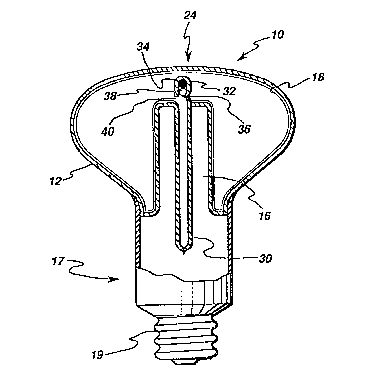
Figure 2 illustrates an electrodeless SEF
lamp in accordance~with one embodiment of the present
; invention~ The SEF lamp of Figure 2 includes an
extended exhaust tube 30; that is, exhaust tube 30 has

RD 22894
, ~
2~33~1~
-- 6 --
an extension 32 through re-entrant cavity 16 for
positioning an amalgam 34 near the apex 24 of the
lamp. Before the lamp is filled through exhaust tube
30, amalgam 34 is inserted through the exhaust tube
with lamp lO in a crown-down position. Then, an
indentation 36, shown in Figure 2 as being relatively
sharp, is ~ormed in the exhaust tube for holding - ~
amalgam 32 in place. The location of indentation 36 ~!i
depends on the optimum operating temperature range for
the particular amalgam employed. If desired, a dose
locating member 38 comprising, for example, a glass
ball, may be inserted after amalgam 34 to further
ensure tha~ amalgam 34 maintains its position toward
or at the end of extension 32. A hole 40 is formed in
~- 15 exhaust tube 30, and envelope 12 is evacuated and
filled therethrough.
Figure 3 illustrates an alternative
embodiment of the present invention w~erein an
~ . .
extension 52 of an extended exhaust tube 50 is
positioned substantially perpendicular to the main
portion of the exhaust tube. Amalgam 34 is positioned
in extension 52 of exhaust tube 50 by forming an
indentation 56 therein in similar manner as described
with reference to indentat~on 36 of Figure 2. As
shown, dose locating member 38 may be employed, i~
desired, to further ensure that amalgam 34 maintains
its position. Evacuation hole 60 is formed in exhaust
tube 50, and envelope 12 is evacu~ted and filled
therethrou~h. Advantageously, by the embodiment of
Figure 3, the amalgam position may be contr~lled
laterally as well as vertically, thus provlding even
further operating temperature control for amalgam 34.

RD 22894
_ 7 _ 213351~
While the preferred embodiments of the ~ -
present invention have been shown and described
herein, it will be obvious that such embodiments are
provided by way of example only. Numerous variations,
changes and substitutions will occur to those of skill
in the art without departing from the invention
herein. Accordingly, it is intended that the
invention be limited only by the spirit and scope of
the appended claims. ~ :

Representative Drawing
A single figure which represents the drawing illustrating the invention.
Administrative Status

2024-08-01:As part of the Next Generation Patents (NGP) transition, the Canadian Patents Database (CPD) now contains a more detailed Event History, which replicates the Event Log of our new back-office solution.

Please note that "Inactive:" events refers to events no longer in use in our new back-office solution.

For a clearer understanding of the status of the application/patent presented on this page, the site Disclaimer , as well as the definitions for Patent , Event History , Maintenance Fee  and Payment History  should be consulted.

Event History

Description Date
Inactive: IPC from MCD 2006-03-11
Time Limit for Reversal Expired 2002-10-03
Application Not Reinstated by Deadline 2002-10-03
Deemed Abandoned - Failure to Respond to Maintenance Fee Notice 2001-10-03
Inactive: Abandon-RFE+Late fee unpaid-Correspondence sent 2001-10-03
Application Published (Open to Public Inspection) 1995-04-05

Abandonment History

Abandonment Date Reason Reinstatement Date
2001-10-03

Maintenance Fee

The last payment was received on 2000-09-28

Note : If the full payment has not been received on or before the date indicated, a further fee may be required which may be one of the following

  • the reinstatement fee;
  • the late payment fee; or
  • additional fee to reverse deemed expiry.

Please refer to the CIPO Patent Fees web page to see all current fee amounts.

Fee History

Fee Type Anniversary Year Due Date Paid Date
MF (application, 3rd anniv.) - standard 03 1997-10-03 1997-09-18
MF (application, 4th anniv.) - standard 04 1998-10-05 1998-09-16
MF (application, 5th anniv.) - standard 05 1999-10-04 1999-09-24
MF (application, 6th anniv.) - standard 06 2000-10-03 2000-09-28
Owners on Record

Note: Records showing the ownership history in alphabetical order.

Current Owners on Record
GENERAL ELECTRIC COMPANY
Past Owners on Record
HSUEH-RONG CHANG
JOSEPH CHRISTOPHER BOROWIEC
ROBERT ARTHUR SENECAL
Past Owners that do not appear in the "Owners on Record" listing will appear in other documentation within the application.
Documents

To view selected files, please enter reCAPTCHA code :


To view images, click a link in the Document Description column. To download the documents, select one or more checkboxes in the first column and then click the "Download Selected in PDF format (Zip Archive)" or the "Download Selected as Single PDF" button.

List of published and non-published patent-specific documents on the CPD .

If you have any difficulty accessing content, you can call the Client Service Centre at 1-866-997-1936 or send them an e-mail at CIPO Client Service Centre.


Document
Description 
Date
(yyyy-mm-dd) 
Number of pages   Size of Image (KB) 
Descriptions 1995-04-05 7 490
Drawings 1995-04-05 3 131
Cover Page 1995-04-05 1 66
Abstract 1995-04-05 1 85
Claims 1995-04-05 3 186
Representative drawing 1999-10-27 1 17
Reminder - Request for Examination 2001-06-05 1 118
Courtesy - Abandonment Letter (Maintenance Fee) 2001-10-31 1 183
Courtesy - Abandonment Letter (Request for Examination) 2001-11-14 1 171
Fees 1996-09-19 1 55
PCT Correspondence 1994-12-23 1 23
PCT Correspondence 1994-12-23 1 22
PCT Correspondence 1994-12-15 1 19