Sélection de la langue

Search

Sommaire du brevet 2133510 

Énoncé de désistement de responsabilité concernant l'information provenant de tiers

Une partie des informations de ce site Web a été fournie par des sources externes. Le gouvernement du Canada n'assume aucune responsabilité concernant la précision, l'actualité ou la fiabilité des informations fournies par les sources externes. Les utilisateurs qui désirent employer cette information devraient consulter directement la source des informations. Le contenu fourni par les sources externes n'est pas assujetti aux exigences sur les langues officielles, la protection des renseignements personnels et l'accessibilité.

Disponibilité de l'Abrégé et des Revendications

L'apparition de différences dans le texte et l'image des Revendications et de l'Abrégé dépend du moment auquel le document est publié. Les textes des Revendications et de l'Abrégé sont affichés :

  • lorsque la demande peut être examinée par le public;
  • lorsque le brevet est émis (délivrance).
(12) Demande de brevet: (11) CA 2133510
(54) Titre français: LAMPE FLUORESCENTE SANS ELECTRODE AVEC MISE EN PLACE OPTIMISEE D'UN AMALGAME
(54) Titre anglais: ELECTRODELESS FLUORESCENT LAMP WITH OPTIMIZED AMALGAM POSITIONING
Statut: Réputée abandonnée et au-delà du délai pour le rétablissement - en attente de la réponse à l’avis de communication rejetée
Données bibliographiques
(51) Classification internationale des brevets (CIB):
  • H01J 65/00 (2006.01)
  • H01J 7/22 (2006.01)
  • H01J 9/00 (2006.01)
  • H01J 9/38 (2006.01)
  • H01J 9/395 (2006.01)
  • H01J 61/24 (2006.01)
  • H01J 61/28 (2006.01)
  • H01J 61/30 (2006.01)
  • H01J 61/42 (2006.01)
  • H01J 65/04 (2006.01)
(72) Inventeurs :
  • BOROWIEC, JOSEPH CHRISTOPHER (Etats-Unis d'Amérique)
  • CHANG, HSUEH-RONG (Etats-Unis d'Amérique)
  • SENECAL, ROBERT ARTHUR (Etats-Unis d'Amérique)
(73) Titulaires :
  • GENERAL ELECTRIC COMPANY
(71) Demandeurs :
  • GENERAL ELECTRIC COMPANY (Etats-Unis d'Amérique)
(74) Agent: CRAIG WILSON AND COMPANY
(74) Co-agent:
(45) Délivré:
(22) Date de dépôt: 1994-10-03
(41) Mise à la disponibilité du public: 1995-04-05
Licence disponible: S.O.
Cédé au domaine public: S.O.
(25) Langue des documents déposés: Anglais

Traité de coopération en matière de brevets (PCT): Non

(30) Données de priorité de la demande:
Numéro de la demande Pays / territoire Date
08/130,935 (Etats-Unis d'Amérique) 1993-10-04

Abrégés

Abrégé anglais


ELECTRODELESS FLUORESCENT LAMP
WITH OPTIMIZED AMALGAM
POSITIONING
Abstract
An amalgam is accurately placed and
retained in an optimal location near the cold spot of
an electrodeless SEF lamp for operation at a mercury
vapor pressure in the optimum range from approximately
four to seven millitorr. The amalgam is positioned at
the tip of an extended exhaust tube near the apex of
the lamp envelope by forming an indentation in the
exhaust tube and, in some embodiments, a dose locating
member in combination therewith. An evacuation hole
is formed below the indentation for evacuation of the
lamp envelope, or bulb, during lamp fabrication. In
an alternative embodiment, the extension of the
exhaust tube is situated perpendicular to the main
portion of the tube to allow for lateral adjustment of
the position of the amalgam, thereby allowing for even
further control of the amalgam operating temperature.

Revendications

Note : Les revendications sont présentées dans la langue officielle dans laquelle elles ont été soumises.


- 8 -
CLAIMS:
1. A method for manufacturing a solenoidal electric field (SEF)
fluorescent discharge lamp, comprising the steps of:
providing a light-transmissive envelope having an interior
phosphor coating for emitting visible radiation when excited by ultraviolet
radiation, said envelops having an apex portion, said envelope further
having a re-entrant cavity formed therein for containing an excitation coil,
said re-entrant cavity having an exhaust tube with an extension toward said
apex portion of said envelope, said extension having a tip;
inserting an amalgam into said exhaust tube and maintaining
said amalgam substantially at said tip of said extension thereof;
forming an indentation in said exhaust tube at a predetermined
location between said re-entrant cavity and said tip of said extension of said
exhaust tube;
forming an evacuation hole in said exhaust tube between said
indentation and said re-entrant cavity; and
evacuating and filling said envelope through said exhaust tube.
2. The method of claim 1, wherein said predetermined location is
such that mercury vapor pressure within said envelope is maintained within
the range from approximately four to seven millitorr during lamp operation.
3. The method of claim 1, further comprising the step of inserting
a dose locating member into said exhaust tube after inserting said amalgam
and before forming said indentation.

- 9 -
4. The method of claim 3, wherein said dose locating member
comprises a glass ball.
5. The method of claim 1, wherein said amalgam is selected from
the group consisting of: indium; a combination of bismuth and indium; a
combination of lead, bismuth and tin; zinc; and a combination of zinc,
indium and tin.
6. The method of any one of claims 1 to 5, wherein said extension
is situated perpendicular to said exhaust tube and said re-entrant cavity.
7. A solenoidal electric field (SEF) fluorescent discharge lamp,
comprising:
a light-transmissive envelope containing an ionizable, gaseous
fill for sustaining an arc discharge when subjected to a radio frequency
magnetic field and for emitting ultraviolet radiation as a result thereof, said
envelope having an interior phosphor coating for emitting visible radiation
when excited by said ultraviolet radiation, said envelope having an apex
portion, said envelope further having a re-entrant cavity formed therein;
an excitation contained within said re-entrant cavity for
providing said radio frequency magnetic field when excited by a radio
frequency power supply;
an exhaust tube having an extension extending through said re-
entrant cavity and toward said apex portion of said envelope, said exhaust
tube having a tip;
an indentation in said exhaust tube at a predetermined location
between said re-entrant cavity and said tip of said extension of said exhaust
tube;
an amalgam situated within said exhaust tube and maintained
in position substantially at said tip of said extension by said indentation.

- 10-
8. The SEF lamp of claim 7, wherein said predetermined location
is such that mercury vapor pressure within said envelope is maintained
within the range from approximately four to seven millitorr during lamp
operation.
9. The SEF lamp of claim 7, further comprising a dose locating
member for operating in combination with said indentation to maintain said
amalgam in position in said exhaust tube.
10. The SEF lamp of claim 9, wherein said dose locating member
comprises a glass ball.
11. The SEF lamp of claim 7, wherein said amalgam is selected
from the group consisting of: indium; a combination of bismuth and indium;
a combination of lead, bismuth and tin; zinc; and a combination of zinc,
indium and tin.
12. A solenoidal electric field (SEF) fluorescent discharge lamp
according to any one of claims 7 to 11, wherein said extension is situated
perpendicular to said exhaust tube and said re-entrant cavity.

Description

Note : Les descriptions sont présentées dans la langue officielle dans laquelle elles ont été soumises.

RD 22894
,~,
: " :
- 1- 21~3510 ~
ELECTRODELESS FLUORESCENT LA~
~ITH OPTIMIZED AMALGAM
. - ..
Field of the Invention
- ,:: :
:: 5 The present invention relates generally to
; ~ - . . ~.:- . ~
~ : fluorescent lamps and, more particularly, to accurate
. .
placement and retention of an amalgam in a solenoidal
: electric field~fluorescent discharge la~p for
optimally control~llng~mercury vapor pressure therein,
which amalgam placement~ and retention do not interfere
wi~h lamp proces~sing and~furthermore are maintained~
during lamp~operat~ion, regardless of lamp orientation. ~ ~-
' _ ~; ,:,
; The~optimum~merc~ury~vapor pressure for
:15 production of ~ 253?~A~ radiation to exoite a phosphar
coating in a fluorescent lamp is approximately six
millitorr, correspondi~ng to a mercury reservoir~ .
temperature of approximately 40 C. Conventional ~-
tubular fluorescent lamps operate at a power density : ~:~
2~ (i.e,, typically measured as power input per phosphor
area) and in a fixture configured to ensure operation
of the lamp at or about a mercury vapor pressure of
six milli~orr (typically in a range from approximately

RD 22894
~33~0
-- 2
four to seven millitorr); that is, the lamp and
fixture are designed such that the coolest location
~i.e., cold spot) of the fluorescent lamp is
approximately 40 C. Compact fluorescent lamps,
however, including electrodeless solenoidal electric
field (SEF) fluorescent discharge lamps, operate at
higher power densities with the cold spot temperature
typically exceeding 50 C. As a result, the mercury
vapor pressure is higher than the optimum four to
seven millitorr range, and the luminous output of the
lamp is decreased.
One approach to controlling the mercury
vapor pressure in an SEF lamp is to use an alloy
capable of absorbing mercury from its gaseous phase in
varying amounts, depending upon temperature
conditions. Alloys capable of forming amalgams with
mercury have been found to be particularly useful.
The mercury vapor pressure of such an amalgam at a
given temperature is lower than the mercury vapor
pressure of pure liquid mercury.
Unfortunately, accurate placement and
retention of an amalgam to achieve a mercury vapor
pressure in the optimum range in an SEF lamp are
difficult. For stable long-~erm operation, the
amalgam should be pl~ced and retained in a relatively
cool location with minimal tempera~ure variation.
Such optimal locations are at or near the tip, or ~ -
apex, of the lamp envelope, or crown. Accordingly, it
is desirable to place the amalgam in an optimal
position n~ar the cold spot of the lamp. Moreover, to
achieve the desired beneficial effects of an amalgam
in an SEF lamp, the amalgam should maintain its
composition and optimized location during lamp

RD 22894
`: ~`
.,..
~1335~0
-- 3 --
processing and manufacturing steps as well as during
lamp operation.
Summa~y_of the Invention
An amalgam is accurately placed and
5 retained in an optimal location near the cold spot of ~- ~
an electrodeless SEF lamp for operation at a mercury `
vapor pressure in the optimal range from approximately
four to seven millitorr. The amalgam is positioned at
the tip of an exhaust tube extension near the apex of ` ~ -
the lamp envelope by forming an indentation therein
and, in some embodiments, using a dose locating member ~-
in combination with the indentation. An evacuation
hole is formed below the indentation for evacuation of
:: :
~ the lamp envelope,;or bulb, during lamp fabrication.
~ .
In an alternative embodiment, the exhaust
tube extension is situated perpendicular to the main
portion of the tube to aIlow for lateraI adjustment of
~ the position of the amalgam, thereby allowlng for even
-~ further control oS the amalgam operating temperature~
.: .
The features~and advantages of the present
invention will become apparent from the ~ollowing
-~ detailed description of the invention ~hen read with
the accompanying drawings in which:
Figure 1 illustrates, in partlal cross
section, a typical electrodeless S~F fluorescent
discharge lamp;
Figure 2 illus~rates, in partial cross `
section, an electrodeless SEF fluorescent discharge

RD 22894
S 1 0
lamp aecording to one embodiment of the present
invention; and
Figure 3 illustrates, in partial cross
section, an electrodeless SEF fluorescen~ discharge
lamp according to an alternative embodiment of the
present invention.
~etailed DescriDtion of th~
I~vention
Figure 1 illustrates a typical
electrodeless SEF fluorescent discharge lamp 10 having
an envelope 12 containing an ionizable gaseous fill.
A suitable fill, for example, comprises a mixture of a
rare gas ~e.g., krypton and/or argon) and mercury
vapor and/or cadmium vapor. An excitation coil 14 is
situated within, and removable from, a re-entrant
cavity 15 within envelope 12. For purposes of
illustration, coil 14 is shown schematically as being
wound about an exhaust tube 20 which is used for
filling the lamp. ~owever, the coil may be spaced
apart from the exhaust tube and ~ound about a core of
insulating material or may be free standing, as
desired. The interior surfaces of envelope 12 are
coated in well-known manner with a suitable phosphor
18. Envelope 12 fits into one end of a base assembly
17 containing a radio frequency power supply (not
shown) with a standard (e.g., Edison type~ lamp base
19 at the other end. Envelope 12 is shown in Figure 1
in a "crown-up", or "base-down", position.
In operation, current flows in coil 14 as a
result of excitatlon by a radio frequency power supply
(not shown). As a result, a radio frequency magnetic
field is established wi~hin envelope 12 which ionizes

~D 22894
.... .
.. .. .
_ 5 _ 2 1 3 ~ S ~ O
and excites the gaseous fill contained therein,
resulting in an ultraviolet discharge 23. Phosphor 18:
absorbs the ultraviolet radiation and emits visible ~ -
radiation as a consequence thereof. -
In accordance with the present invention, a
properly constituted amalgam is accurately placed and
retained in an optimal location in an SEF lamp for
operation at a mercury vapor pressure in the optimum -
range from approximately four to seven millitorr,~
which amalgam maintains its composition and location
during lamp processing as well as during lamp `
operation, regardless of lamp orientation. In ~-
particular, the amaIgam is~accurately positioned and
retained at a relatively cool location with minimal
temperature variation near the apex of the lamp
envelope. The apex of~the lamp envelope typically
comprises the cold spot of the lamp.
An exemplary amalgam comprises a
combination of bismuth~and indium. Another exemplary
amalgam comprlses pure indium. Still another
exemplary amalgam~comprises;a combination of lead,
bismuth and tin,~such as described in commonly
; assigned V.S. Pat~. No. i,262,231 of;J.M. Anderson and
P.D. Johnson, issued April 14, 19~1, which is
;~ 25 incorporated by refe~rence~herein. Yet~another amalgam -~
may comprise zinc. And yet another amalgam may ~-
comprise a combination of zinc, indium and tin. Each
amalgam has its own optimum range of operating
temperatures.
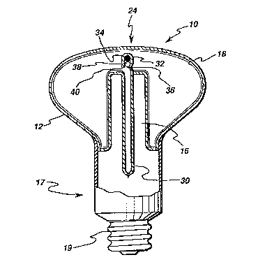
Figure 2 illustrates an electrodeless SEF
lamp in accordance~with one embodiment of the present
; invention~ The SEF lamp of Figure 2 includes an
extended exhaust tube 30; that is, exhaust tube 30 has

RD 22894
, ~
2~33~1~
-- 6 --
an extension 32 through re-entrant cavity 16 for
positioning an amalgam 34 near the apex 24 of the
lamp. Before the lamp is filled through exhaust tube
30, amalgam 34 is inserted through the exhaust tube
with lamp lO in a crown-down position. Then, an
indentation 36, shown in Figure 2 as being relatively
sharp, is ~ormed in the exhaust tube for holding - ~
amalgam 32 in place. The location of indentation 36 ~!i
depends on the optimum operating temperature range for
the particular amalgam employed. If desired, a dose
locating member 38 comprising, for example, a glass
ball, may be inserted after amalgam 34 to further
ensure tha~ amalgam 34 maintains its position toward
or at the end of extension 32. A hole 40 is formed in
~- 15 exhaust tube 30, and envelope 12 is evacuated and
filled therethrough.
Figure 3 illustrates an alternative
embodiment of the present invention w~erein an
~ . .
extension 52 of an extended exhaust tube 50 is
positioned substantially perpendicular to the main
portion of the exhaust tube. Amalgam 34 is positioned
in extension 52 of exhaust tube 50 by forming an
indentation 56 therein in similar manner as described
with reference to indentat~on 36 of Figure 2. As
shown, dose locating member 38 may be employed, i~
desired, to further ensure that amalgam 34 maintains
its position. Evacuation hole 60 is formed in exhaust
tube 50, and envelope 12 is evacu~ted and filled
therethrou~h. Advantageously, by the embodiment of
Figure 3, the amalgam position may be contr~lled
laterally as well as vertically, thus provlding even
further operating temperature control for amalgam 34.

RD 22894
_ 7 _ 213351~
While the preferred embodiments of the ~ -
present invention have been shown and described
herein, it will be obvious that such embodiments are
provided by way of example only. Numerous variations,
changes and substitutions will occur to those of skill
in the art without departing from the invention
herein. Accordingly, it is intended that the
invention be limited only by the spirit and scope of
the appended claims. ~ :

Dessin représentatif
Une figure unique qui représente un dessin illustrant l'invention.
États administratifs

2024-08-01 : Dans le cadre de la transition vers les Brevets de nouvelle génération (BNG), la base de données sur les brevets canadiens (BDBC) contient désormais un Historique d'événement plus détaillé, qui reproduit le Journal des événements de notre nouvelle solution interne.

Veuillez noter que les événements débutant par « Inactive : » se réfèrent à des événements qui ne sont plus utilisés dans notre nouvelle solution interne.

Pour une meilleure compréhension de l'état de la demande ou brevet qui figure sur cette page, la rubrique Mise en garde , et les descriptions de Brevet , Historique d'événement , Taxes périodiques et Historique des paiements devraient être consultées.

Historique d'événement

Description Date
Inactive : CIB de MCD 2006-03-11
Le délai pour l'annulation est expiré 2002-10-03
Demande non rétablie avant l'échéance 2002-10-03
Réputée abandonnée - omission de répondre à un avis sur les taxes pour le maintien en état 2001-10-03
Inactive : Abandon.-RE+surtaxe impayées-Corr envoyée 2001-10-03
Demande publiée (accessible au public) 1995-04-05

Historique d'abandonnement

Date d'abandonnement Raison Date de rétablissement
2001-10-03

Taxes périodiques

Le dernier paiement a été reçu le 2000-09-28

Avis : Si le paiement en totalité n'a pas été reçu au plus tard à la date indiquée, une taxe supplémentaire peut être imposée, soit une des taxes suivantes :

  • taxe de rétablissement ;
  • taxe pour paiement en souffrance ; ou
  • taxe additionnelle pour le renversement d'une péremption réputée.

Veuillez vous référer à la page web des taxes sur les brevets de l'OPIC pour voir tous les montants actuels des taxes.

Historique des taxes

Type de taxes Anniversaire Échéance Date payée
TM (demande, 3e anniv.) - générale 03 1997-10-03 1997-09-18
TM (demande, 4e anniv.) - générale 04 1998-10-05 1998-09-16
TM (demande, 5e anniv.) - générale 05 1999-10-04 1999-09-24
TM (demande, 6e anniv.) - générale 06 2000-10-03 2000-09-28
Titulaires au dossier

Les titulaires actuels et antérieures au dossier sont affichés en ordre alphabétique.

Titulaires actuels au dossier
GENERAL ELECTRIC COMPANY
Titulaires antérieures au dossier
HSUEH-RONG CHANG
JOSEPH CHRISTOPHER BOROWIEC
ROBERT ARTHUR SENECAL
Les propriétaires antérieurs qui ne figurent pas dans la liste des « Propriétaires au dossier » apparaîtront dans d'autres documents au dossier.
Documents

Pour visionner les fichiers sélectionnés, entrer le code reCAPTCHA :


Pour visualiser une image, cliquer sur un lien dans la colonne description du document. Pour télécharger l'image (les images), cliquer l'une ou plusieurs cases à cocher dans la première colonne et ensuite cliquer sur le bouton "Télécharger sélection en format PDF (archive Zip)" ou le bouton "Télécharger sélection (en un fichier PDF fusionné)".

Liste des documents de brevet publiés et non publiés sur la BDBC .

Si vous avez des difficultés à accéder au contenu, veuillez communiquer avec le Centre de services à la clientèle au 1-866-997-1936, ou envoyer un courriel au Centre de service à la clientèle de l'OPIC.


Description du
Document 
Date
(aaaa-mm-jj) 
Nombre de pages   Taille de l'image (Ko) 
Description 1995-04-05 7 490
Dessins 1995-04-05 3 131
Page couverture 1995-04-05 1 66
Abrégé 1995-04-05 1 85
Revendications 1995-04-05 3 186
Dessin représentatif 1999-10-27 1 17
Rappel - requête d'examen 2001-06-05 1 118
Courtoisie - Lettre d'abandon (taxe de maintien en état) 2001-10-31 1 183
Courtoisie - Lettre d'abandon (requête d'examen) 2001-11-14 1 171
Taxes 1996-09-19 1 55
Correspondance reliée au PCT 1994-12-23 1 23
Correspondance reliée au PCT 1994-12-23 1 22
Correspondance reliée au PCT 1994-12-15 1 19