Note: Descriptions are shown in the official language in which they were submitted.
; ~ W O 93/21353 21~ 3 7 2 9 PCT/G B93/00637
Y1brat~ng ring motor for feedlng part~cular substances.
This lnventlon relates to motors the motor
effect of which can be employed in two dlfferent ways
giving lt an important but by no means exclusive
application in apparatus for manufacturlng metal matrlx
composite materials, i.e. metals incorporating
particulate substances. The term "partlculate
substances" is used hereln to include substances ln
chopped or short fibre form in addition to powdered and
granular substances.
Very fine powders are difficult to make flow
in a controlled manner and one means of producing a
flow is to cause the material to vlbrate. The present
invention is based on the discovery that lf a ring
disposed substantlally horizontally lS caused to
vibrate radially, preferably at its natural frequency,
a flowable substance deposited on the upper surface of
the ring moves to the central aperture of the ring and
~- further, that material tends during ltS fall throuqh
29 the ring to move then towards the axls of the ring
under the radial compressing force of gas present in
the hole and vibrating at the same frequency as the
ring.
- According to this invention there is provided
a motor comprising a ring arranged with its axis in an
up and down direction, and having its upper surface
either disposed substantially horizontally or with a
downward inclination towards the axis of the ring, and
mqans for imparting radial vibration to the ring so to
3o form a node on the axis of the ring.
Where the motor is used as a feed motor for a
particulate substance, means is provided for directing
the substance on to the upper surface of the ring.
A hopper for the material may conveniently
have its lower end secured to the ring in a manner to
vibrate with the ring.
W093/213~3 21 ~ 3 7 2 ~ PCT/GB93/00637~
- 2 -
The upper surface of the ring may
advantageously be lnclined towards the axls of the ring
and may be smooth or formed with concentric grooves or
a spiral groove of saw-tooth section. In one
construction the groove or grooves are of ratchet-to~th
section with the steeper face of the section facing
towards the axis of the ring.
A useful way of producing metal matrix
composites ls to atomize the molten matrix metal by gas
or other means and lntroduce into the atomized spray
the second phase which can be in the form of solid
metalllc or non-metallic particles or chopped fibres
entr~lned in a gas stream. The combined stream of metal
matrix and second phase particles may then be directed
on to a substrate where it solidifies, or may be
allowed to solidify as a powder. This procedure has
many advantages but is not free from technical
problems. One such problem is to achieve some degree of
penetration. of the metal spray with the gas-entrained
second phase to produce a spray in which the second
phase is uni,ormly distributed so as to give a
solidified product which has a uniformly distributed
second phase. A special difficulty arises when the
second phase consists of a very fine powder which may
be sub-micron in size. In these circumstances it is
difficult to add the particles to the metal stream at a
uniform controlled rate with the result that the
efficiency of the operation is low.
The invention also provides apparatus for
3~ mixing a particulate substance with a matrix metal
comprising, for the addition of the particulate ~`
substance, a feed motor comprislng a ring arranged with
its axis in an up and down direction, and having its
upper surface either disposed substantially
horizontally or with a downward inclination towards the
axis of the ring, means for imparting radial vibration
~ W O 93/21353 21~3729 PC~r/GB93/00637
~ .
- 3 -
to the ring so to form a node on the axls of the rlng
and means for depositlng the substance on to the upper
surface of the ring, for directing a stream of the
metal in molten form axially downward through the rlng,
and means for directing one or more downwardly incllned
jets of atomizing gas on to the combined flow of molten
metal and partlculate material.
A process may thus be obtained in which a
stream of liquid, which may be coherent or particulate,
is passed through a ring, the top surface of which may
be sloping inwards and the lnner surface of which is
not necessarily parallel, containing in the central
aperture of the rlng a gas which the rlng is radiall~
resonating at high frequency, and in which a
particulate solid is passed on to the top surface of
the vibrating ring such that both the particulate solid
and the stream of liquid are forced by the vibration of
the rinq and the vibration of the gas enclosed in the
central aperture towards a central nodal position in
the ring where they are brought together and may or may
not intermingle, the combined streams then being
atomized either by gas or other means, to form a spray
in which the component parts are uniformly distributed.
Such a spray may be directed onto a surface where lt
solidifies to form a spray deposit or may be allowed to
solidify in flight to form a particulate material or
may be collected as a liquid containing a dispersion of ,
solid particles.
, The process is applicable to any metal that
3o can be melted and atomized into a stream of liquid
particles. Moreover, any powder or chopped fibre can be
used provided the powders or chopped fibre will pass `~
easily into the central aperture of the ring.
A particular feature of the process is that
the powder or chopped fibre is forced by the radial
vibration of the ring to move from the hopper towards
21~129 . ~
WO93/21353 PCT/GB93/00637
-- 4
the central aperture. This forced movement can be
intenslfied by machlning rlngs or spirals on the top
surface of the resonator
In an application of the lnvention to an
apparatus to carry out this process the second phase
particles and the metal stream are moved to a central
nodal positlon on passage through a ring that is
vibrating ln an ultrasonlc mode. The rapidly vibratlng
ring has two motor effects. Firstly it causes the
particulate solid to move across the top face of the
vibrating ring towards a central position. The movement
can be accentuated by providing a downward slope on the
top face of the rlng. Secondly the vibrating rlng
causes the gas within the ring to vibrate
correspondingly such that a node is formed in the gas
at a central axial position. Any streams of liquid or
particulate solid are moved towards this node on
passage through the ring. In the case of a metal matrix
composite being made from a powder which may be a
ceramic or oxide and a stream of liquid metal, the
powder is moved rapidly towards the liquid metal stream
across the top face of the rlng and is forced into
contact with the liquid metal stream which itself is
moved to a central position, if not already there, and
extended axially. The movement of both the powder and
the liquid metal into a central nodal position as they
pass through the ring enables the subsequent atomizing
to give a uniform distribution of the second phase ln
the spray and ultimately in the solidified spray
deposit.
The ring should vibrate at or close to its ~;
natural resonant frequency to maximise the displacement
amplitude. The shape and dimensions of the rlng should
be such as to optimise the radial motion and to avoid
fatigue failure but, within this constraint, it is
possible to contour both the external and any internal
r
~ 1 ~3 3 7 2
~ WO93/21353 PCT/GB93/00637 ~
i,,. I ~
surfaces to minimise the risk of fatigue and the
dissipation of vibrational energy. Stainless steel has
been found to be a satisfactory material from which to
make the ring. I.
The frequency of vibration is preferably
selected to satisfy several criteria. Relatively low
frequencies such as 50-5000 Hz give rise to
unacceptable des1gn constraints and to distressing
audible disturbance which at high powers can be a
serious health hazard. Above 18 kHz the vibratlon
ceases to be audible to most humans. The range of 18-25
kHz usually avoids discomfort or aural damage. Higher
frequencies can be used but for a given power input the
displacement amplitude is correspondingly reduced, the
t5 beneficial effect with regard to the invention is
- reduced and the power effectlveness is lower.
Furthermore there may again be an un~cceptable
engineering design constraint in that the radially
resonant ring may have too small a diameter to be
useful.
The invention will now be described in more
- detail with reference by way of example to the
accompanying diagrammatic drawings ln which:
Figure 1 shows an axial section a first
embodiment of the invention as applied in an apparatus
for mixing a particulate substance with a matrix metal,
and
Figure 2 is a view similar to Figure 1 of a
modified form of the apparatus.
,~ .
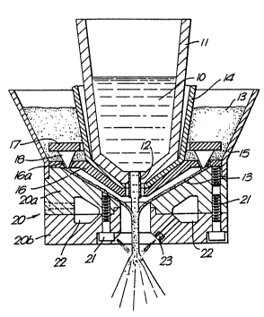
Referring to Figure 1, the matrix molten
metal 10, e.g. aluminium alloy, is contained in a tun~
dish 11 at the bottom of which is a pouring nozzle 12
for the metal. The particulate material, which in this
instance may be silicon carbide in the form of 10 um
powder 13, is contained in an annular hopper comprising
an inner wall 14 encircling the tun-dish 11, an outer
r - .
WO 93/21353 213 ~ 7 2 ~ PCr/GB93/00637 . ~
-- 6 ~ .
wall 15 and a bottom wall 16. A series of valve
apertures 16a are formed in the bottom wall 16, and an
annular plate 17 carrying valve elements 18 engaged in
the valve apertures can be raised and lowered to
control the outlet area of the hopper. The side wall 15
of the hopper is secured to the upper end of a
stainless steel ring 20 comprising upper and lower
parts 20a, 20b secured together by bolts 21. An annular
plenum chamber 22 is formed in the parts 20a, 20b
jointly and gas under pressure, which may be a gas to
which the metal is inert such as nitrogen or argon, is
supplied to the chamber and from the chamber is
supplied to a ring of nozzles 23 mounted in the ring 20
and inclined downward towards the axis of the ring 20.
The ring 20 is caused by means not shown to vibrate at
20 kHz by way of concentrators and transducers from a 3
kw ultrasonic generator, and the ring 20 is so designed
that it resonates at the selected vibration frequency.
In operation of the apparatus, the outer wall
of the hopper vibrates with the ring 20 and causes the
powder to flGw through the valve apertures 16a on to the
upper surface of the ring. The radial vibration of the
riny causes the powder to move radially inward along
the upper surface of the ring and into the central
aperture at the same time as the matrix metal 10 flows
downwardly through the aperture. A flow of the inert
gas above the powder on the upper surface of the ring
is caused to vibrate radially when it enters the
c,entral aperture of the ring and the powder is impelled
3~ by the vibration into close contact with the stream of
metal and in some cases partially to penetrate the j~;
metal stream as it accelerates in a downward direction
and attenuates. The combined stream of particles and
molten metal is atomized by the jets of qas issuing
from the nozzles 23 to give a spray having a uniform
distribution of powder particles. The combined stream
WO93/21353 ~1 ~ 3 7 Z 9 PCT/GB93/00637
- 7
may be directed onto a cool substrate to form a deposlt
of a metal matrix composite having a uniform dispersion
of the siLicon carbide powder in the aluminium alloy.
It will be understood that any metal or alloy ~`
can be used as the matrix and any powder or powder
mixture or short or chopped fibre can be used as the
added phase.
The resonating ring 20 centralises the metal
stream and prevents or reduces sideways break-up. This
ls a very useful characteristic since small deviatlons
- in the metal stream can cause major changes in
behaviour on atomization.
Provision may be made for cooling of the
resonating ring 20 b'r a suitable coolant flowing
1~ through passages formed in the ring.
The mechanism of the centralising movement
within the central aperture is related to the pattern
of vibration of the gas. The molecules of gas in the
central aperture are set in vibration and produce a
20 node at a central position. Any solid or iiquid within
this aperture is forced towards the node, the driving
force diminishing as the nodal position approached.
This causes constriction of a stream of liquid metal
and of any suspended particles. The constriction causes
25 a stream of liquid metal to become smaller in diameter
~; and elongate usually in a downward direction assisted
by gravity; the constriction also has the effect of
`~ driving particles into the attenuating liquid stream. ~
Thje effect occurs with particles having a very wide 5
3o range of sizes including sub-micron particles. This
application of the invention is particularly useful :
with sub-micron particles because their handling and
.
propulsion by conventional means from a hopper towards
the liquid metal stream is difficult if they are not
agglomerated into granules.
The velocity of gas within the central
,:,
-,~
~VO 93/21353 213 3 72 ~ PC~r/GB93/00637
- 8
aperture of the vlbrating rlng 20 lS not lmportant
unless the velocity is high. High velocities cause
particles to be propelled so rapidly through the
central orifice that there is too little time for the
centralising forces to operate effectively. Lower ~as
velocities, however, may be very useful to maintain the
entrainment of small particles and also to prevent
- blow-back during atomlzation.
A further important point of note is that the
upper surface of the ring need not be inclined downward
towards the axis but may be horizontal sinc~ the motor
effect driving particulate material radially inward is
still obtained. Also the rlng lS not necessarily
clrcular and the cross-section of the ring may be
shaped either for concentrating the vibrational effect
at the central part or to conform with external
requirements or for a compromise between the two. In
all cases it is however necessary, for energy efficient
operatlon, to ensure that the applied frequency
, 2Q coincides with the current resonant frequency of the
j ring.
¦ In the modified construction shown in Figure
¦ 2, the ring 20 is formed in one piece, and the gas
nozzles 23 are formed in a separate hollow ring member
- 25 24 disposed just below and concentrically with the
ring. As in the previous construction the gas jets
incline downwardly and towards the axis of the ring.
I This construction has the advantage that the ring is
¦ iealsier to manufacture than the two-part ring and that
1 3o the ring is easier to tune to the required frequency
¦ and resonates more effectively. It also reduces the ~.
likelihood of fatigue failure of the ring but has the
disadvantage of lengthening the free-fall of the metal
and powder before atomization takes place.
Also in the arrangement of Figure 2, the
upper surface of the ring is formed with a series of
~ WO93/21353 ~1~3 7 2 9 PCT/GB93/00637
. . .-
g
' I
concentric grooves of somewhat saw-tooth form, or
preferably of ratchet-tooth form wlth the steeper face
of the tooth facing towards the axis of the ring. A
hellcal groove of similar section may be provided
instead of the concentric grooves if desired. The
grooves drive the powder more effectively towards the
central aperture because the surfaces vibrate in a
horizontal mode. Any vertical compor~ent of the
vibration has the supplementary effect of causing
fluidizatlon of the powder flowing across the
upper surface of the ring and promotes unlform
distribution of the particles.
In another application of the inventlon, the
- feed motor constituted by the radially vibrating ring may be employed to produce a uniform flow of fine
~- powder from a hopper through the central aperture of
the ring. In such embodiments, the cuter wall of the
opper is secured to the ring at or near the periphery
~ of the ring. Fine powders which do not readily flow are
-~ 20 caused by the vibration of the ring and the hopper to
be deposited on the upper surface of the ring and to
flow towards the central aperture in a steady stream.
When vibration is stopped the flow of powder stops
almost instantly. Such an apparatus may operate in
conjunction with a weight sensing device to fill
~- containers with a predetermined weight of powder. If
the pow~er has a higher degree of flowability the
hopper may be provided with a valve to control the flow
' of the powder onto the upper surface of the ring.
In another application of the feed motor, the
ring is employed in conjunction with a tun-dish 11 of rt--`
molten metal 10 arranged to flow in a stream downward
--~ coaxially through the centre of the ring. Provision is
made also for a flow of air or other gas through the
centre of the ring about the flow of molten metal. When
the ring is caused to vibrate at resonant frequency the
:
W o 93/21353 ~ 1 ~ 3 7 2 9 Pc~r/G B93/00637.~
1 0
radial vibration of the gas stream about the molten
metal within the central aperture of the ring
centralizes the flow of molten metal and prevents or
reduces sideways break-up of the metal stream. As
previously described, this is advantageous where the
stream of molten metal is to be atomized to produce
either a powder or a spray-formed product.
The radial vibration of the ring is
accomplished through a transducer system in a manner
known ~E se and will not be described here. The amount
of vibrational energy required is an important factor
because the radially inward driving force is
proportional to the amplitude of vibrations which is,
in most cases, proportional to the energy input, so ;
that a degree of control of the rate of flow can be
obtained by adjusting the power input and hence the
amplitude of the vibrations. It has been found in
practice that in most cases it is necessary to have an
input of at least 1 kW. For dealing with large
quantities o'. materials, energies between 3 and 10 kW
may be necessary. The amount of energy required also
depends on the design of the resonator. A well designed
resonator will resonate with a minimum dissipation of
energy whereas a poorly designed, or poorly matched
one, will be inefficient. For continuous operation it
may be necessary to cool the ring to avoid a rise in
temperature that would change the acoustic properties.
Either external or internal cooling may be
used but in the case of internal cooling the cooling
3o channels needed either for gas or water cooling must be
designed to minimise the deleterious effects on the ~-
acoustic performance of the ring.
The equipment need not be used in a
completely vertical attitude because the centralising
effect operates irrespective of gravity and this can be
a useful way of deflecting the stream of metal through
21~72~ ~
.. :;.. WO93/21353 PC~/GB93/00637 ~',,4.;S,
1 1 - ! j '-
a small desired angle. Gravitational effects will, of
course, cause deviation of the metal stream and
asymmetry of distribution of the particles which is not
desirable in most cases.
-
~; ~ 25
~.
~; i.
'.