Note: Descriptions are shown in the official language in which they were submitted.
~33~31 ~:
WINDOW LACE ASSEMBLY HAVING EMBEDDED
ANTENNAS AND METHOD FOR MAKING SAME
BACKGROUND OF ~HE INVENTION
This invention relates generally to an antenna for use in an
automotive vehicle and specifically to a pair of antennas which are embedded
within a window lace of an automotive vehicle.
Automotive vehicles commonly include devices requiring antennas
For example, cellular telephones have become an increasingly popular option
within automotive vehicles. Cellular telephones require a cellular telephone
antenna which is commonly an antenna mounted to the vehicle in addition to a
separate factory installed radio antenna. Often the cellular phone antenna is
permanently attached to the vehicle's back window or temporarily attached to theinside of a window or windshield by suction cups. Permanent installation of a
cellular telephone antenna to a back window generally requires disassembly of
portions of the vehicle interior trim for routing of the appropriate wires and then
reassembly of the trim. Unfortunately, exterior mounted antennas are sometimes
. .
visually displeasing and such antennas often serve to notify potential thieves that ; .
, a cellular telephone unit is located within the vehicle. Moreover, it is ofter
visually displeasing to have multiple antennas mounted on the vehicle, as may
be the case where the vehicle has AM/FM radio and cellular phone antennas ` :~
, ... ..
mounted thereon. Internally mounted antennas such as those mounted by
20 suction cups are also sometimes unsightly and potentially interfere with the
driver's vision. . ;;
~''-' '~; .
., .,.,.., ., ~" ,
~:~33g31 ':
In accordance with the present invention, the above disadvantages ;
are overcome by concealing an antenna within a window lace assembly. Two
.
prior patents are known which show a radio antenna within an automotive
weatherstrip. These are shown in: U.S. Patent 4,758,166 entitled "Concealed
Radio Antenna," issued to Bonnett et al. on July 19, 1988; and U.S. Patent
2,481,978 entitled "Automobile Radio Coupler and Method of Communication," ; .: ;`
issued to Clough on September 13, 1949. Furthermore, it is known within the :
weatherstrip and window lace industry that a wire may be inserted with a molding ~ ; i` `
during the extrusion process to control the lace's shape and shrinkage
;,.
characteristics while adding longitudinal strength. While the preceding antenna `
devices and patents depict improvements in the art, the traditional problems ;:: -
associated with a cellular telephone antenna in addition to a radio antenna are ; .
still present. ~``/` `~
: `: '' ' ' ~',.
SUMMARY OF THE INVENTION :;
In accordance with the present invention, a preferred embodiment .
of a window lace assembly comprises a window lace with a pair of antennas ` ~ -
embedded therewithin. The antennas are electrically isolated frorn one another.
In the preferred embodiment, the two antennas are linearly aligned with eac
other along an elongated dimension of the window lace and are separated by a
notched-away portion. In an alternate embodiment, the two antennas are parallel
and adjacent to one another throughout a substantial portion of the window lace's ~ t~, .
elongated dimension. In both embodiments, the first antenna can be used with . .:
~, ~ .... ~-;
, .. ... .
an AM/FM radio receiver or the like and the second antenna can be used with
a cellular telephone device.
The window lace assembly with embedded antennas of the present
invention is advantageous. Both a cellular telephone antenna and a radio :
5 antenna can be concealed within an easily installed window lace. Thus, the
unsightly appearance of a pair of visible antennas is avoided. Furthermore, the
integration of parts saves assembly time, part proliferation and cost. Moreover,
the potential for theft of the cellular telephone device is reduced since the cellular
telephone antenna is now hidden.
10Additional advantages and features of the present invention will
become apparent from the following description and the appended claims, taken
in conjunction with the accompanying drawings.
BRIEF pESCRlPTlON OF THE DRAWINGS
Figure 1 is a perspective view showing the preferred embodiment ~;
15 of the present invention window lace assembly in relation to an automotive
vehicle;
Figure 2 is an elevation view of the present invention window lace
assembly of Figure 1; ~.-
Figure 3 is a side elevation view of the present invention window ~ `
20lace assembly of Figure 2; ;. ~ ~
Figure 4 is a cross sectional view of the present invention window ~ -
lace assembly, taken along line 3-3 of Figure 1; ;~
' ~ .
~ l 3 ~ 3
Figure 5 is a cross sectional view showing an alternate embodiment
of the present invention window lace assembly, taken aiong line 3-3 of Figùre 1; ~ .
and :: .
Figure 6 is a perspective view showing the proGess used to .. -.manufacture the preferred embodiment of the present invention window lace ;~
assembly of Figure 1. ;;
DETAILED DESCRIPTION OF THE PREFERRED EMBODIMENT .. ` `~
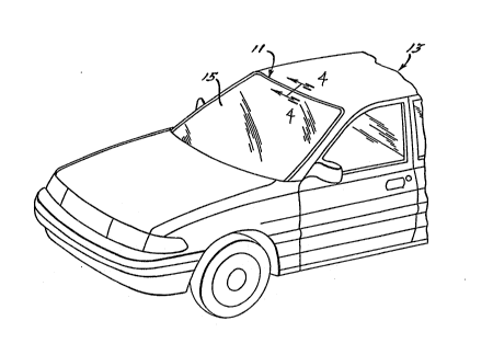
Referring to Figure 1, a window lace assembly 11 of the present `.invention is shown installed on an automotive vehicle 13. Window lace assembly
10 11 is located around three.sides of front windshield 15. Of course, window lace
assembly 11 can be located on only one side or as desired around the sides of
a windshield 15 or other window such as a back light. As can best be seen in `~
Figures 2-4, the preferred embodiment of window lace assembly 11 comprises
a window lace 17, a first conductive member 19 such as a first antenna and a
15 second conductive member 21 such as a second antenna. h.
As shown in cross section, window lace 17 has an aesthetically
pleasing cap portion 23, an intermediate portion 25 perpendicularly located .:
thereto, a flexible finger 27 protruding from one side of intermediate portion 25, ;~
and a stationary finger 29 which protrudes from an opposite side of intermediate20 portion 25. Intermediate portion 25 and flexible finger 27 fit within a gap 31 ~ `.. `j:`
defined between an edge 33 of window 15 and an offset 35 of a vehicle body , ~; .
panel 37. Furthermore, stationary finger 29 is adjacent to the backside 39 of .j, ,~
.. ~ .,, . ~
,, ., " .
:~=
~339~
:' !
window 15. Moreover, cap portion 23 overlaps a portion 41 of body panel 37
and a portion 43 of window panel 15 thereby aesthetically covering gap 31 from
view. Window panel 15 is held onto a flange 45 of body panel 37 by a urethane
adhesive bead 47 as is known to one skilled in the art.
Antenna 19 has an elongated dimension 61 measured between a
first end 63 and a second connecting end 65. Antenna 19 also has a circular
cross sectional dimension 67 which is significantly thinner than elongated
dimension 61. Similarly, antenna 21 has an elongated dimension 71 measured
between a first end 73 and a second connecting end 75. Antenna 21 also has
a circular cross sectional dimension (shown as 67) which is significantly thinner
than elongated dimension 71. Both antenna 19 and antenna 21 are completely
embedded within window lace 17, however, connecting ends 65 and 75,
respectively, must be accessible for electrical attachment. Antenna 19 is
electrically connected to a radio receiver 81 and a suitable grounding plane 83.1~ Antenna 21 is electrically connected to a cellular telephone device 85 and an
appropriate grounding plane 87, if required. Furthermore, in the preferred
embodiment, antennas 19 and 21 are positioned coincident with an elongated
dimension 91 of window lace 17 and are linearly aligned with one another
.
therein. Nevertheless first ends 63 and 73 are spatially isolated from one . .~ `
20 another by a notched-away portion 93 of window lace 17 therebetween.
:.; ', '
An alternate embodiment of a window lace assembly 101 is shown .
in Figure 5. Window lace assembly 101 is comprised of a window lace 103, a
first conductive member for use as a radio antenna 105, and a second ~
:
- ~ 33~3~ :
conductive member.for use as a cellular telephone antenna 107. Window lace : ;
103 is similar in configuration to that of the preferred embodiment, however, in .~
this assembly 101 antennas 105 and 107 are positioned adjacent and parallel to ~ ~ ;
one another within window lace 103. Furthermore, antenna 105 and antenna . ~:
107 are electrically isolated from one another by a section 109 of window lace " -
103. The electrical connections for each antenna 105 and 107 can be made at ~ ~ ~
the same end of window lace 103. Moreover, a notched-away portion, as is . ~.. ;
used in the preferred embodiment, is not necessary with this window lace `i ~
.....
assembly 101. This embodiment is suitable for longer length antennas, for loop
10 antennas that need to be connected at both ends, or for window laces that
cannot have a notched away portion.
Window laces 17 and 103 are made from an elastomeric rubber or ;~
thermoplastic such as EPDM (ethylene-propylene terpolymer). Also, conductive i~
members 19, 21, 105 and 107 are preferably discrete insulated copper wires. . . `
The preferred embodiment of window lace assembly 11 can be
manufactured by using conventional extruding equipment with modified cutting
dies. Referring to Figure 6, a roll 111 longitudinally feeds wire 113 into a cross- .,,
head extrusion die 115. Simultaneously, an extruder 117 extrudes polymeric
resin around wire 113 and through die 115. Next, a match metal die 120
notches-away the window lace intermediate portion 25, flexible finger 27, . ~ .
,. .- ,
stationary finger 29 and wire 113. Another match metal die 121 then cuts .
window lace assembly 11 to predetermined lengths. Finally, a stripping device~ ,.
i` . ;: i ~
119 can be used in combination with match metal die 121 to remove the window' -.
6 . .
. " ., .; ..
~ 3~3~
, ` . , .
lace 17 from around wire 113 in order to later make the necessary electrical
connections.
While various embodiments of the present invention window lace
assembly having a pair of antennas embedded therewithin have been disclosed,
5 it will be appreciated that various modifications may be made without departing
from the present invention. For example, the window lace assembly of the
present invention may have more than two conductive members embedded
therewithin. Furthermore, while a specific window lace shape has been
described, many other profiles may be employed without departing from the
10 scope of this invention. Also, electrica? devices other than cellular telephones,
which require a dedicated antenna, may be connected to the second antenna
Moreover, a conductive metallic mesh or metallic flat tape rnay be embedded
within the window lace instead of discrete insulated copper wires. Various
materials have been disclosed in an exemplary fashion, however, other materials
15 may of course be used. It is intended by the following claims to cover these and
any other departures from the disclosed embodiments which fall within the true
~ .
spirit of this invention.
! ` I ' - ` '
7 ~ ~
~;
' `: ";
.. , ,,, .,, ,. , ., , ~ ~::