Note: Descriptions are shown in the official language in which they were submitted.
CA 02134296 2006-06-30
-1-
METHOD OF FOLDING COLLATIONS HAVING TWO
DIFFERENT SIZE DOCUMENTS
Field of the Invention
The invention disclosed herein relates generally to
apparatus for processing sheets and more particularly with
apparatus for nesting one sheet with another, folded sheet.
Background of the Invention
As shown in F. J. Rouan et al. U.S. Pat. No. 2,736,999,
apparatus has been provided for feeding individual pieces of
mailing material, from each of a plurality of hoppers, to an
intermittently movable conveyor on which one of the pieces of
material is nested within another, pre-folded piece of material
preparatory to stuffing the assembled pieces into an envelope.
As shown in Luperti U.S. Pat. No. 4,898,570, a method and
apparatus have been provided for half folding sequentially and
nesting a plurality of identically sized paper sheets. Thus it
is generally known in the art to nest one sheet within another,
folded, sheet.
Heretofore, folders, such as the aforementioned folders,
have been limited to folding and nesting a collation of sheets
having the same size.
There is now an interest in forming collations of documents
of more than one size and folding such collations with the smaller
documents nested in the fold of the larger documents. For
example, it is desired that a full size insurance statement (or
collation of statements) be folded around a smaller size check
that is
-2-
2134296
to be mailed with the statement. The typical collating
machines and folders do not easily provide for such
special processing because of the problem of controlling
the smaller document in the collating machine and the
folder.
It is an object of the present invention to provide
an improvement to folders that will allow the folder to
perfoxxa such nested folding of collat.lons of different
size documents.
Summazry of the invention
The present invention provides a method and
apparatus for nest folding smaller documents of a
collation into the fold of the larger documents of the
collation. It has been found that such nest folding can
be achieved by bouncing the smaller documents out of a
buckle chute while the first fold is being made to the
larger documents.
In, accordance with the present invention, a method
for nest folding at least one smaller document of a
collation while folding larger documents of the collation
comprises the steps of: providing a buckle chute folder
having a plurality of buckle chutes with one of the
buckle chutes including a kicker structure adjacent a
buckle chute stop; transporting to the buckle chute
folder a collation having documents of at least two
sizes; feeding the collation into the buckle chute having
the kicker structure; buckling the larger of the
documents into a nip of fold rollers as the lead edge of
the collation hits the buckle chute stop; bouncing the
smaller of the documents out of the buckle chute as the
larger of the documents enter the nip of the fold
rollers; and completing the first fold of the larger
documents with the smaller documents riested within the
first fold.
The method comprises the further steps of providing
the buckle chute with, a steel spring as the kicker
structure; and forming a collatio of two different size
CA 02134296 2006-06-30
-3-
documents before transporting the collation to the buckle
chute folder.
In accordance with the present invention, an improvement
for nest folding smaller documents of a collation within the
folds of the larger documents of the collation is provided to
a buckle chute folder having a plurality of buckle chutes
with fold stops therein and a plurality of fold rollers. The
improvement comprises kicking structure adjacent the fold
stop in one of the buckle chutes. The kicker structure
bounces the smaller documents out of the buckle chute as the
larger of the documents buckle into the nip of a pair of the
fold rollers after being stopped by the fold stop in the one
of the buckle chutes. In the preferred embodiment the kicker
structure is a steel spring.
Description of the Drawings
The above and other objects and advantages of the
present invention will be apparent upon consideration of the
following detailed description, taken in conjunction with
accompanying drawings, in which like reference characters
refer to like parts throughout, and in which:
Fig. 1 is a top plan view of a dual in-line collating
machine in accordance with the present invention;
Fig. 2 is a side elevational view of the collating
machine of Fig. 1;
Fig. 3 is a perspective view of the downstream end of
the collating machine of Fig. 1;
Fig. 4 is a horizontal sectional view taken on the plane
indicated by line 4-4 in Fig. 1;
Fig. 5 is a sectional view taken on the plane indicated
by line 5-5 in Fig. 2;
Fig. 6 is a sectional view taken on the plane indicated
by line 6-6 in Fig. 2;
Fig. 7 is a sectional view taken on the plane indicated
by line 7-7 in Fig. 2;
2134296
-4-
FIG. 8 is a side elevational view of the downstream end of
the collating machine of FI.G. 1 and a chute of a buckle chute
folder;
FIG. 9 is similar to FIG. 8 showing a smaller document and
a larger document being conveyed out of the collating machine
into the folder; and
FIG. 10 is similar t:o FIG. 9 showing the smaller document
nested in a first fold of the larger document.
Detailed Description of the Present Invention
In describing the preferred embodiment of the present
invention, reference is made to U.S. Pat.. Nos. 4,640,506 and
4, 805, 891, both assigned to the assignee of the present invention
fcr showing the capability of stacking sheets of paper in the
same or reverse order in which they are fed to the collating
machine.
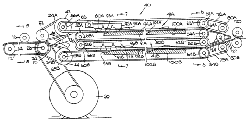
Referring now to the drawings, the preferred embodiment of
the present invention is shown wherein a system, generally
designated 10, for nesting smaller documents into larger
dccuments includes feedinq apparatus (not shown), a transport 20,
a dual level accumulator or collator, generally designated 40,
an.d a folder 130. System 10 processes two different size
dccuments fed from one feeder or separate feeders (not shown),
fcrms a collation of the documents and nests the smaller document
in the larger document for further processing, for example by an
inserting machine (not shown).
Referring now to FIGS. 1, 2 and 5, transport 20 includes two
endless, lower flat belts 12 which travel around pulleys 14 and
15. Each of belts 12 has an upper reach which is opposed by at
least one biased, idler roller 16. The number of rol:Lers opposing
each belt depends on the length of transport 10 and size of the
smallest document that will be handled by transport 20. The
rollers opposing each belt are longitudinally spaced a distance
that is less that the length of the smallest
~~..
CA 02134296 2006-06-30
-5-
document to be transported. Rollers 16 and belts 12 are
approximately one inch wide and have a relatively high
coefficient of friction. This structure deters any skewing
of the documents being transported and provides maximum
control of the smaller documents that are transported to
accumulator 40. At the downstream end of transport 20 a pair
of upper and lower dual function pulley/rollers 22 and 24 are
used to transport documents to accumulator 40 and to drive
the belt and pulley system of accumulator 40, which is
described below. In the preferred embodiment of the present
invention, lower pulley/rollers 24 and pulleys 15 are fixed
to drive shaft 26 which is coupled to a conventional pulley
system coupled to motor 30. Upper pulley/rollers 22 are in
turn conventionally driven, for example by gear d'rive.
Accumulator 40 is a dual pocket accumulator with
identical upper and lower pockets, generally designated 41A
and 41B respectively. Each of pockets 41A and 41B is capable
of accumulating a one or more of the small documents in the
order to which they are fed into the respective pocket, and
accumulating one or more of the larger documents in the same
or reverse order in which they are fed into the pocket. Like
components in pockets 41A and 41B are designated with the
same reference numeral with an additional reference of
letters A or B for the upper or lower pocket respectively.
Because the pockets are identically structured with like
components having the same reference numerals, except for the
A or B designated, the two sections will be described once
without the A and B designations.
Referring now to Figures 1 and 2, transport 20 is
coupled to accumulator 40 by two pairs of upper and lower 0-
ring belts 34A,34B. Upper and lower belts 34A,34B travel
around pulley/rollers 22 and 24 respectively at one end and
pulleys 42 and 44 at the other end. Between pulleys 42 and
44 there is a wedge-shaped deflector 46, which has a tapered
end facing transport 20. Deflector 46 is fixedly secured to
CA 02134296 2006-06-30
-6-
a shaft 48 which pivots between two positions, as shown in
Figure 2. The pivoting motion of deflector 46 is controlled
by a rotary solenoid (not shown) having an internal return
spring. A more detailed description of the operational
structure of deflector 46 is provided in U.S. Patent
5,083,769, previously noted.
Each of pockets 41A and 41B include a transport system
which controls the movement of documents fed into accumulator
40. The accumulator transport system comprises three upper,
endless 0-ring belts 50 and two lower, flat belts 60. Flat
belts 60 are each opposed by a set of longitudinally spaced
steel balls 90 that rest against belts 60. Three pulleys 62
are rotatably mounted to shaft 52 while two idler pulleys 64
are rotatably mounted on shaft 54. Three pulleys 66 are
secured to shaft 56 while two pulleys 68 are secured to shaft
58. Shafts 52, 54, 56 and 58 are rotatably mounted in the
frame (not shown) of accumulator 40 in a conventional manner.
0-ring belts 50 are suspended on the pulleys 66 and 62. Flat
belts 60 are suspended on pulleys 68 and 64.
Each set of steel balls 90 are suspended over a
corresponding flat belt 60 from a housing 92 that is rigidly
mounted to a bar 94 which is transversely mounted to a frame
member (not shown) of accumulator 40. In the lower section
of each housing 92 there are a plurality of holes 96 through
which balls 90 protrude and rest against flat belts 60.
Balls 90 are biased toward belts 60 by the weight of the
balls. Balls 90 have room in housing 92 to move upward to
handle different thickness of documents. In the preferred
embodiment of the present invention, steel balls 90 are
spaced approximately one and 1/4 inches apart to deter
skewing of the smaller documents. Rollers similar to rollers
16 in transport 20 may be used instead of steel balls 16
should more control of the smaller documents be desired.
As best seen in Fig. 6, two exit roller pairs, generally
designated 70 include upper idler rollers 72
-7- 2134296
which are rotatably mounted on shaft 52 and lower rollers 74
which are secured to shaft 54. In addition to transporting
ccllations from accumulator 40, exit rollers 70 act as
registration stops for sheets transported into accumulator 40.
Each of upper exit rollers 72 have a center groove by which it
functions as a pulley over which 0-ring belt '78 is suspended.
Belts 78 are suspended downstream on pulleys 80. Shaft 54 is
operatively coupled to a drive system, such as a clutch and brake
system, (not shown) in a conventional manner whereby shaft 54,
and thus lower exit rollers 74, rotate to transport collations
from accumulator 40, but do not rotate when the collations are
being formed.
As best shown in FIGS. 2 and 7, a pair of ramp guide blocks
91 are mounted to a trarisverse mounting arm riot shown. Guide
blocks 91 include a ramp section 93 on the upstream side for
intercepting a leading end of sheets as they are transported
individually by the transport system of accumulator 40. Each of
guide blocks 91 includes an L-shaped portion on the downstream
side defined by horizontal support surface 94 and vertical
abutment surface 96. Guide blocks 91 are positioned in
accumulator 40 such that vertical abutment -ourface 96 is a
distance from exit rollers 70 approximately equal to, but not
less than, the length of the larger document being processed in
accumulator 40. A more detailed description of the slidable
mounting and positioning of guide blocks 91 is provided in U.S.
Pat. Nos. 4,805,891 and 5,083,769.
In accordance with the present invention, a second pair of
ramp guide blocks 100 are mounted to a second transverse mounting
arm not shown. Each of guide blocks 91 has a shape similar to
guide blocks 91, having a ramp section 102, a horizontal support
surface 104 and a vertical abutment surface 106. Vertical
abutment surface 106 may by smaller than vertical abutment
surface 96 if accumulator 40 is handling a lessor number of small
2134296
-8-
dccuments than larger documents. Suitable paper side guides 110
are secured to side frame member (not shown) on each side of
accumulator 40 for gui_ding the sheets 6.
The collations fed front accumulator pockets 41A and 41B are
funneled into a single paper path by an output transport 121
which includes exit belts 78 suspended over pulley/rollers 72 and
80. Guide plates 122 and idler roller 124 assist iri the exiting
of the collations. A pair of conveying rollers 120 are suitably
jcurnaled, supported and driven by a drive system (not shown) for
ccnveying collations which are fed from the accumulator 40.
Rcllers 120 are positioned between accumulator 40 and folder 130
such that positive control of the smal.ler document(s) in the
collation is maintained.
Folder 130 is a conventional six roller folder with three
buckle chutes 131, 132 and 1:33. For the purpose of describing the
present invention only the first four rollers 141-145 of folder
130 are shown (FIGS. 9 an(i 10) . A bypass plate 134 is positioned
in place of a fourth buckle chute in the folder. Iri addition to
a conventional fold stop 136 that is used in typical buckle
chutes, such as in buckle chutes 132 and 133, buckle chute 131
has a spring loaded bounce, generally designated 140, that works
in conjunction with but not in place of the folcl stop 136 within
chute 131. Spring loaded bounce 140 includes a spring loaded
kicker 150 and kicker stops (not shown) defining both the forward
and back position of kicker 150. The forward or normal position
locates kicker 150 in the path of the collation coming into
buckle chute 131. The back position limits the deflection of
kicker 150 such that it travels just slightly farther than fold
stop 136. It has been found that if kicker 150 is allowed to go
any farther past stop 136 the reaction time of spring kicker 150
is not fast enough to keep the small document justified to the
large document while i.t is being kicked out of chute 131.
Chute 131 is similar in structure to a typical bouncing
buckle chute which is typically used for
~~A
9-
2134296
inverting sheets. The present invention uses the
w
bouncing buckle chute to nest small documents, such as a
check, into the fold of the larger documents of the
collation.
Having explained the details of the apparatus
hereinabove, the manner of operation will now be
explained. In accordance with the preserzt invention two
different size documents are fed from one or more input
devices into accumulator 40 to form a collation of the
io two different size documents. For example, a dual stage
burster (not shown) may feed a full size (81-1 by 11)
statement from one stage and a smaller size (5 by 2}z)
check from a second stage. One or more of the smaller
documents, which must be nested inside the folded larger
documents of the collation, are fed into accumulator 40
first. After the smaller documents have been fed, the
larger documents are fed into accumulator 40.
Both size documents fed from the input devices are
transported to accumulator 40 by transport 20. The
multiple idler rollers 16 opposing the driven flat belts
12 deter any skewi.ng of the documents as they are
transported into accumulator 40.
For each collation, the smaller documents are fed
seriatim from a corresponding upstream feeder (not shown)
to transport 20. Then the larger documents of the
collation are fed seriatim to transport 20 by their
corresponding feeder (not shown). With deflector 46
pivoted to deflect documents to upper pocket 45A (Fig. 2)
the small and large documents are conveyed seriatim in
the order received to upper pocket 41A by belts 34 and
pulley/rollers 22 and 24. The documents are directed
into the respective pockets 41A or 41B by deflector 46
located at the entry of accumulator 40. As a document
enters accumulator 40, it is in the control of
pulley/rollers 22 and 24 which then pass the document
into the bite of the accumulation transport system in
pocket 41A or 41B which,includes two continuously moving,
lower flat belts 60 opposed by steel balls 90.
-10- 2134296
The documents are transported over the fir9t set of guide
blocks 91 and over the second set of guide blocks 100 and against
exit rollers 70. Upper 0-ring belts 50, which are continuously
moving, provide additional drive to transport the documents
through the accumulator, but the primary function of the of
0-ring belts 50 is to slap down the trailing edge of the
documents as they pass over ramp sections 93 and 102 of guide
blocks 91 and 100 respectively. Exit rollers 70 are clutched on
and off as required during the accumulation of documents into a
collation. At the completion of a collation, rollers 70 are
clutched on releasing the collation which is transported into
folder 130.
As the first document, i.e., the smaller and nested
document, enters accumulator 40, it is transported over both sets
of guide blocks 91 and 100 to the output end of accumulator 40
and is stopped with its lead edge at exi_t rollers 70 and its
trail edge settled just past ramp section 102. The larger
dccument is then transported over both sets of guide blocks 91
and 100 stopping when its lead edge hits exit rollers 70 and its
trail edge settles just past ramp section 93. At: this point, the
dccuments are all justified to the lead edge and accumulated in
the proper order. As exit rollers 70 are activated the total
ccllation moves into the bite of the output transport 121 between
accumulator 40 and folder 1:30. Output trar.isport 121 funnels the
two accumulator paths back to one paper path and transports the
collation into the bite of folder 130.
As a collation containing both large ancl small document
enters folder 130 bypass plate 134 forces the collation by
without any alteration to the collation through the fold rollers
and into buckle chute 131. Fold stop 136 in chute 131 is set to
fold 1/3 of the large document in the chute. This length also
allows the small document to be completely iriserted into buckle
chute 131. As the lead edge of the documents hits stop 136
CA 02134296 2006-06-30
-11-
the fold takes place and the documents begin to exit buckle chute
131. The large documents are being folded and removed by fold
pinch rollers 144 and 145. Normally the small document would be
partially or totally left behind in buckle chute 131. But in the
present invention spring bounce 140 works to complete the nesting
of the smaller document into the fold of the larger document
(FIG. 10). As the collation enters buckle chute 131, the leading
edge of the collation forces a spring kicker 150 to rotate from
its normal position (shown in phantom) loading spring 152. As the
larger documents of the collation buckle and begin to exit from
buckle chute 131, the force of the wrapped torsion spring 152
rotates kicker 150 back to its normal position which pushes the
smaller document(s) out with the larger documents of the
collation. The smaller document(s) is now nested inside the fold
of the large documents which now continues into buckle chute 132
to begin a second fold before leaving folder 130 for further
processing, for example, in an inserting machine.
The preferred embodiment of the present invention has been
described for collations having documents of two different sizes.
It will be appreciated that further sets of guide blocks can be
added to accumulator 40 to form collations having documents of
more than two different sizes, wherein the smallest document is
accumulated first and the largest document is accumulated last.
In an alternate embodiment (not shown) of the present
invention, a normal force is applied to the collation such that
the smaller document is removed from the buckle chute as the
larger documents are folded by the folding rollers. For example,
instead of kicker spring 150, a spring or brush is mounted in a
wall of the buckle chute to provide a normal force to the
collation as the collation enters and leaves the buckle chute.
This normal force arrangement causes the smaller documents to
exit the buckle chute with the larger documents.
2134296
While the present invention has been disclosed and
described with reference to a single embodiment thereof,
it will be apparent, as noted above that variations and
modifications may be made therein. It is also noted that
s the present invention is independent of the machine being
controlled, and is not limited to the control of
inserting machines. It is, thus, intended in the
following claims to cover each variation and modification
that falls within the true spirit and scope of the
present invention.