Note: Descriptions are shown in the official language in which they were submitted.
~13~300
IMPROVED INFLATABLE PROSTHESIS
Technical Field
The present invention relates generally to medical
devices and procedures. More specifically the present invention
relates to an infl~t~ble prosthesis for implantation within the
periurethral tissues of a patient to treat urinary incontinence.
Background of the Invention
It is known to implant inflatable prostheses in the
periurethral tissues of a patient to provide support to the
urethral sphincter as a treatment for urinary incontinence. Such
implants are described, for example, in U.S. Patent No.
4,832,680 to Haber et al. The prostheses, similar to tiny
balloons, are introduced into the periurethral tissues and
positioned, one on either side of the urethra, in an uninflated
condition. The prostheses are then inflated by infusing saline
solution through a cannula. As the prostheses expand they exert
pressure and cause coaptation of the urethra.
The inflatable prostheses normally used for this
procedure comprise a balloon mounted around a main body and
anchored to the body at its rearward end. As the balloon is
inflated, the major direction of elongation is longitudinal, that
iS, parallel to the urethra. Thus if the prostheses are not
~134~00
positioned closely enough to the urethra, or if the periurethral
tissues tend to be inelastic, as in the case of scar tissue from
previous surgery or radiation treatment, considerable additional
inflation of the prostheses is required to result in relatively
minor increases in coaptative pressure.
Inflatable prostheses are known which expand
primarily in a radial direction. Such prostheses are disclosed,
for example, in U.S. Patent No. 3,834,394 to Hunter et al.
These prostheses comprise a balloon whose opposite ends are
o linked to prevent axial elongation. As the balloon is first
inflated, the only possible direction of expansion is radially.
The infl~t~kle prosthesis of the aforementioned U.S. Patent No.
3,834,394 is disclosed only with respect to vascular
applications. Furthermore, even though such a prosthesis might
s provide advantages in terms of enhanced lateral pressure, the
pressure tends to be exerted at only a single point.
Thus there is a need for an improved inflatable
prosthesis which when positioned within the periurethral tissues
will exert radial pressure against the urethra but which will
exert that pressure along a substantial length of the urethra.
There is a further need for an infl~t~ble prosthesis
for impl~ntin~ in periurethral tissues which will expand in such
a way as to provide a greater margin of error with respect to
placement of the devices.
There is also a need for an inflatable implant which
expands primarily radially but which exhibits some limited
degree of longitudinal expansion.
Summary of the Invention
As will be seen, the present invention overcomes
these and other problems associated with prior art inflatable
implants. Stated generally, the inflatable implant of the present
invention is adapted to treat urinary incontinence when
positioned within the periurethral tissues inflates in such a
3s manner as to exert a radial pressure against the urethra and
3 ~ ~ 3~3~ ~
exerts that pressure along a substantial length of the urethra. The implant expands in such a
way as to provide a greater margin for error in placement of the device by expanding primarily
radially while exhibiting a limited degree of axial elongation.
Stated more specifically, the present invention comprises an inflatable prosthesis
5 comprising a structural member having front and back ends and an exterior surface and having
a longitll(lin~l bore formed in the back end of the structural member dimensioned to receive a
needle therewithin. An elastomeric balloon has a back end in sealing association with the
structural member and has a front end extending beyond the front end of the structural member
such that a portion of the structural member is contained within the balloon. The structural
0 member has a port means defined therein for placing the bore in fluid co~ ication with a
port location exterior of the structural member which is contained within the balloon, whereby
fluid infused into the bore passes through the port means and into a space between the balloon
and the exterior surface of the structural member to inflate the balloon. Elastomeric means has
a rearward portion attached to the structural member at a location rearward of the port means
15 and has a forward portion attached to the front end of the balloon for partially constraining
axial expansion of the balloon as the balloon is infl~te~l
In a plef~ d embodiment the elastomeric member comprises an elastomeric
tubular housing sealed to the perimeter of the structural member at a location rearward of the
port location. The elastomeric tubular housing is stretched against the exterior surface of the
2 o structural member and has a hole formed therethrough at a location removed from the port
location. When fluid exits the port under pressure, it distends the housing and passes between
the exterior surface of the structural member and the housing to pass through the hole into the
.~
~ ~ 34 30Q
balloon. The elastomeric housing returns against the exterior surface of the structural member
upon release of the pressure to prevent fluid from returning back through the port, whereby the
balloon is m~int~inrd in an inflated state.
In another aspect of the preferred embodiment, the structural member comprises
a needle guide having a longit~ in~l bore formed therewithin and having at least one radial port
formed in a side wall thereof. A needle guide core has a portion disposed within the central
longitll(lin~l bore of the needle guide and is pierceable by a needle. The needle guide core has
a transverse bore in col"~"l-,-ir~tion with the radial port of the needle guide such that fluid
infused by a needle inserted in the longitll-lin~l bore of the needle guide passes through the
transverse bore of the needle guide core and through the radial port of the needle guide.
Thus the present invention seeks to provide an improved inflatable prosthesis
which when positioned within the peliureLlllal tissues will exert radial pressure against the
urethra but which will exert that pressure along a substantial length of the urethra.
Further the present invention seeks to provide an inflatable prosthesis for
implanting in peliuleLl~ldl tissues which will expand in such a way as to provide a greater
margin of error with respect to placement of the devices.
Further still the present invention seeks to provide an inflatable implant whichexpands primarily radially but which exhibits some limited extent of axial elongation.
Other aspects, features and advantages of the present invention will become
2 o appalellL upon reading the following specification, when taken in conjull~;Lion with the drawings
and the appended claims.
Brief D~li~lion of the D~wi~
FIG. 1 is a cross-sectional view of an inflatable prosthesis according to the
present invention.
FIG. 2A is an end view of a needle guide of the inflatable prosthesis of FIG.
1. FIG. 2B is a side view of the needle guide of FIG. 2A.
A
~134300
FIG. 3A is an end view of the needle guide of
FIGS. 2A-B with a needle guide core molding installed therein.
FIG. 3B is a sideview of the needle guide and needle guide core
molding of FIG. 3A. FIG. 3C is a cross-sectional view taken
s along line 3C-3C of FIG. 3B.
FIG. 4A is an end view of an inner housing
molding used to manufacture the inflatable prosthesis of FIG.
1. FIG. 4B is a cross-sectional view taken along line 4B-4B of
FIG. 4A.
FIG. 5A is an end view of the inner housing
molding of FIGS. 4A-B showing a plug disposed within the
bore of the inner housing molding and a port formed in the
housing molding wall. FIG. SB is a sideview of the inner
housing molding and plug of FIG. 5A. FIG. 5C is a cross-
l5 sectional view taken along line SC-5C of FIG. 5B.
FIG. 6A is an end view of a balloon of the
inflatable prosthesis of FIG. 1. FIG. 6B is a cross-sectional
view taken along line 6B-6B of FIG. 6A.
FIG. 7 is a side cutaway view showing the inner
20 housing molding and plug of FIGS. SA-C being bonded to the
needle guide with needle guide core molding of FIGS. 3A-C.
FIG. 8 is a side cutaway view showing the
assembly of FIG. 7 with pressure being applied to the bond.
FIG. 9 is a side cutaway view showing the balloon
25 of FIG. 6A-B being bonded to the assembly of FIG. 7.
FIG. 10 is a side cutaway view of the assembly of
FIG. 9 showing pressure being applied to the bonds.
FIG. 11 is a side cutaway view of the assembly of
FIG. 9 showing how excess portions of the needle guide core
30 molding and inner housing molding and plug are trimmed away
to complete the assembly of the infl~t~ble prosthesis.
FIG. 12 is a side cutaway view of the inflatable
prosthesis of FIG. 1 showing a needle inserted into the needle
guide with needle guide core and depicting the prosthesis in
35 varying stages of inflation.
213~300
Detailed Description of the Disclosed Embodiment
Referring now in more detail to the drawings, in
which like numerals indicate like elements throughout the
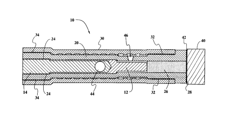
several views, FIG. 1 shows an inflatable prosthesis 10
5 according to the present invention. A needle guide 12 has a
needle guide core 14 mounted thereto.
An inner housing 20 in the shape of a generally
tubular sleeve fits over the needle guide 12 and needle guide
core 14. The inner housing 20 is bonded to the needle guide
lO core 14 at a bonding location 24 adjacent the rearward ends of
the needle guide 12 and inner housing 20. A plug 26 is
disposed within the inner housing 20 adjacent the forward end
28 of the inner housing.
A balloon 30 in the shape of a generally tubular
sleeve is disposed around the inner housing 20 and is bonded to
the inner housing at a forward bonding location 32 and at a
rearward bonding location 34. The balloon 30 is bonded around
the entire periphery of the inner housing 20 at the two bonding
locations 32, 34 so as to form an airtight seal between the
20 balloon and the inner housing between the two bond locations
32, 34.
A cylindrical felt plug 40 comprised of a suitable
material such as polyethyleneterephthalate is bonded to the
forward end of the plug 26 and to the forward end 28 of the
2s inner housing 20 at a bonding location 42. The purpose of the
felt plug 40 is to promote tissue ingrowth and to inhibit
migration of the infl~t~ble prosthesis 10 once implanted.
A radial port 44 is formed through the needle guide
12 and needle guide core 14. An orifice 46 is fo.med in the
30 wall of the inner housing 20 at a location which is both axially
and angularly offset from the port 44. By means of the ports 44
and orifice 46 the interior of the needle guide 12 is in fluid
communication with a location interior of the balloon 30 and
exterior of the inner housing 20.
~ ~ ~4 3~
Referring now to FIGS. 2A and 2B, the needle
guide 12 of the disclosed embodiment is comprised of titanium
and has a cylindrical main portion 48, a reduced cylindrical
forward portion 50, and a forward end 51. The needle guide 12
5 has an axial bore 52 formed in its rearward end 54. Opposed
radial holes 56 are formed through the walls of the needle guide
12 and intersect the bore 52 adjacent its forward end 58.
FIGS.3A-C depict a needle guide core molding 60
assembled to the needle guide 12. The needle guide core
molding 60 is formed from Dow Corning Q7-4720 silicone.
The needle guide core molding 60 has a forward portion 61
disposed within the longitudinal passage 52 (FIGS. 2A-B) of
the needle guide 12. An intermediate portion 62 of the needle
guide core molding 60 is disposed immediately rearward of the
15 rear end 54 of the needle guide 12 and has an outer diameter
corresponding to that of ~e cylindrical main portion 48 of the
needle guide 12. An enlarged rear portion 64 of the needle
guide core molding 60 will eve~hl~lly be trimmed away to forrn
the completed needle guide core 14 but provides a convenient
20 means for h~n-lling the needle guide 12 and needle guide core
molding 60 during assembly.
A transverse bore 66 is formed in the forward
portion 61 of the needle guide core molding 60 between the
opposed holes 56 in the cylindrical main portion 48 of the
25 needle guide 12. In combination, the holes 56 in the needle
guide 12 and the transverse bore 66 in the needle guide core
molding 60 form the radial port 44.
Referring now to FIGS.~4A-B, an inner housing
molding 70, formed from Dow Coming Q7-4735 silicone, takes
30 the form of a generally tubular sleeve. The inner housing
molding 70 includes forward and rear collar sections 71, 72
joined by an intemlediate section 73 of reduced outer diameter.
The inner housing molding has a forward end 74 and a rearward
end 75. A longitudinal passage 76 extends the length of the
35 inner housing molding 70. An ~nn~ r flange 77 is forrned at
* Trade Mark
A
the front end of the forward collar section 71. An extension 78
extends forward of the ~nn~ r flange 77. The extension 78 will
be trimmed away as one of the last steps of manufacture to form
the inner housing 20 but provides a convenient means for
5 holding the inner housing molding 70 during the manufacturing
process.
FIGS. 5A-C show an inner housing assembly 80
comprising the inner housing molding 70 with silicone plug
insert 81 disposed within the longitudinal passage 76 of the
o inner housing molding. The plug insert 81 is formed from Dow
Corning Q7-4840 silicone. The radially extending orifice 46 is
also shown extending through the wall of the reduced
intermediate section 73 of the inner housing molding 70.
Referring now to FIGS. 6A-B, the balloon 30 is
formed from Dow Corning Q7-4720 silicone as a generally
tubular sleeve. The balloon has a longitudinally extending
passage 82. A plurality of ~nn~ r ribs 84 are formed on the
inner wall 86 of the balloon 30 at longitudinally spaced-apart
intervals to promote symmetrical inflation, as will be
20 hereinbelow described.
Manufacture of the inflatable prosthesis 10 will
now be explained. Starting with the needle guide of FIGS. 2A-
B, a pin (not shown) having an outer diarneter corresponding to
the inner diameter of the holes 56 in the needle guide main
25 body portion 48 is positioned through one hole 56, through the
main body portion 48 of the needle guide 12, and out the
opposite hole S6. The needle guide 12 and pin are then placed
into a mold which extends beyond the end 54 of the needle
guide and has cylindrical cavities of suitable configuration to
30 form the intermediate and rearward portions 62, 64 of the
needle guide core 14. Dow Corning Q7~720 silicone Is then
injected into the mold, filling the bore 52 of the needle guide 12
except for the space occupied by the pin, and thereby forming
the needle guide core molding 60. When the silicone has cured,
35 the pin is removed, leaving the transverse recess 66.
* Trade Mark
~134300
The construction of the inner housing assembly 80
will next be explained. A pin (not shown) having an outer
diameter corresponding to the inner diameter of the longitudinal
passage 76 in the inner housing molding 70 is inserted into the
5 rearward end 74 of the inner housing molding. A shoulder
fommed on the pin confronts the rearward end 75 of the inner
housing molding 70 and pemmits only a predetermined length of
the pin to be inserted into the inner housing molding. Viscous
silicone, preferably Dow Coming Q7-4840 silicone, is then
o injected into the longitudinal passage 76 of the inner housing
molding 70 from the forward end 74 the molding. A second pin
having a diameter corresponding to the longitudinal passage 76
of the inner housing molding 70 and having a shoulder formed
thereon to engage the forward end 74 of the inner housing
15 molding and thereby limit the length of the pin which can be
inserted into the longitudinal passage, is inserted into the
forward end 74 of the inner housing molding 70. The entire
assemblage, including pins, is then placed into a fixture of
predetemlined length which exerts an axial compressive force
20 on the pins and imparts pressure on the silicone plug insert 81
during curing. After the silicone plug insert 81 is cured, the
pins are removed.
Referring now to FIG. 7, the inner hous ing
molding 70 is now installed onto the needle guide 12 and
25 associated needle guide core molding 60. The inner housing
molding 70 is first swelled with a suitable expanding agent,
e.g., freon. The rearward end 75 of the inner housing molding
70 with plug insert 81 is then inserted over the forward end Sl
of the needle guide 12 and advanced rearward over the
30 intermediate portion 62 of the needle guide core molding 60
until the rearward end of the inner housing molding 70
confronts the enlarged rear portion 64 of the needle guidc corc
molding 60. As the expanding agent evaporates, the inncr
housing molding returns to its original size fitting ti~hll~
35 against the periphery of the needle guide with needle guidc corc
213~300
- molding. When the expanding agent has completely evaporated
from the inner housing molding 70, a suitable bonding agent,
such as Dow Corning Q7-4840 silicone, is applied between the
intermediate portion 62 of the needle guide core molding 60
s and the overlying portion of the inner housing molding 70.
As next shown in FIG. 8, heat and radially inward
pressure are applied around the periphery of the inner housing
molding 70 adjacent the bond location 24 until the silicone
bond has cured. In the disclosed embodiment a gluing fixture
88 heated to a temperature of 260~-270~F. is applied to the
periphery of the inner housing molding 70 for approximately
four minutes with sufficient force to compress the diarneter of
the assembly by 0-10% of its uncompressed diameter.
Referring now to FIG. 9, the balloon 30 is next
installed onto the inner housing molding 70. The balloon 30 is
first swelled with a suitable expanding agent, e.g., freon. The
expanded balloon 30 is then slipped over the forward end 74 of
the inner housing molding 70 and advanced longitudinally
rearward over the inner housing molding until the leading edge
of the balloon bottoms out against th-e enlarged rear portion 64
of the needle guide core molding 60. After the expanding agent
has evaporated from the balloon, a silicone such as Dow
Corning Q7-4840 silicone, is applied bet~veen the collars 71, 72
of the Lnner housing molding 70 and the overlying portions of
the balloon 30. Then, as shown in FIG. 10, heat and radially
inward force are applied to the periphery of the balloon 30 at
the front and rear bond locations 32, 34. In the preferred
embodiment, the heat and radially inward force are applied by
means of a pair of gluing fixtures 90, 92, which are heated to a
temperature of 260~-270~F. and applied to the periphery of the
balloon 30 for approximately four min~ltes with sufficient force
to compress the diameter of the assembly by up to 10% of its
uncompressed diameter.
The final step in the manufacturing process is
illustrated in FIG. 11. The forward portion 78 of the inner
~13~300
housing molding 70 and the portion of the silicone plug insert
81 lying therewithin are trimmed off along a transverse plane
indicated by the line A-A, which plane is coincident to the
forward edge of the annular flange 77. Similarly, the rear
s portion 64 of the needle guide core molding 60 is trimmed away
along the transverse plane indicated by the line B-B, which
plane is coincident to the rearward edge 75 of the inner housing
molding 70. The cylindrical felt plug 40 (FIG. l) is then
bonded to the forward end of the structure at the bonding
lO location 42 to complete the assembly of the inflatable prosthesis
10 depicted in FIG. l.
Inflation of the prosthesis 10 is illustrated in FIG.
12. A non-coring needle 94 having a forward end 95 and an
orifice 96 adjacent the forward end is inserted into the needle
lS guide core 14 from the rearward end 98 of the prosthesis 10.
The needle is in fluid comm~lnication with a syringe (not
shown). The needle 94 is advanced until its forward end 95
bottoms out against the forward end 58 of the longit~ in~l bore
52 of the needle guide 12. In this position the orifice 96 at the
20 forward end 95 of the needle 94 is axially aligned with the
radial port 44 formed through the needle guide 12 and needle
guide core 14.
A suitable inflation medium such as a saline
solution is then infused from the syringe through the needle 94.
25 The inflation medium exits the orifice 96 of the needle 94 and
passes through the radial port 44 in the needle guide 12 and
needle guide core 14. Fluid pressure distends the inner housing
20 slightly outward, and the inflation medium passes between
the needle guide 12 and the distended inner housing 20, exits
30 through the orifice 46 in the wall of the inner housing, and
passes into the space between the inner housing 20 and the
balloon 30. As the inflation medium is infused through the
needle and along the fluid path into the balloon 30, the balloon
begins to inflate.
213~30~
As shown in FIG. 12, the elastic character of the
inner housing 20 partially constrains axial elongation of the
prosthesis 10 as the balloon 30 is inflated but permits some
expansion in the axial direction. The dashed line 101A
s illustrates the configuration of the balloon 30 of the inflatable
prosthesis 10 when 1 cc of the inflation medium has been
infused, and the dashed line 101B illustrates the position of the
forward end 100 of the prosthesis at that stage of inflation. As
can be seen, the primary direction of expansion is radially
o outward, with only a minor elongation of the prosthesis in the
axial direction.
The dashed lines 102A, 102B illustrate the
configuration of the balloon 30 of the inflatable prosthesis 10
after 2 cc of the inflation medium has been infused, it being
15 understood that the rearward end 98 of the prosthesis 10
remains fixed in location throughout the inflation process as a
result of the prosthesis being mounted to the needle 94. At this
stage of inflation, the primary direction of expansion is still
radially outward, but there is proportionately more elongation
20 of the prosthesis 10 in the axial direction.
The configuration of the prosthesis 10 after
infusion of 3 cc of the inflation medium is shown by the dashed
lines 103A, 103B. At this stage of inflation, the primary
direction of expansion is now in the axial direction, and there is
25 only a minor component of expansion in the radial direction.
When fluid pressure from the syringe is relaxed,
the resilient inner housing 20 returns to its normal position
imposed tightly around the perimeter of the needle guard 12.
This tight fit is further enhanced by the pressure exerted against
30 the outer surface of the inner housing 20 by the inflation
medium within the balloon 30. The inner housing 20 thus
serves as a checkvalve, preventing the inflation medium within
the balloon 30 from returning back through the radial ports 44
and leaking out of the prosthesis 10.
2134300
The capability of the prosthesis 10 to expand in
both a radial and an axial direction affords certain advantages
over prior art inflatable prostheses. Whereas fully constraining
axial elongation of a balloon results in all expansion being
s directed radially outward, and whereas unconstrained axial
elongation of a balloon results subst~nti~lly all of the expansion
being directed axially, the partial axial constraint provided by
the elastic inner housing 20 causes expansion of the balloon 30
to have significant radial and axial components. When the
o inflatable prosthesis 10 is, for example, implanted in
periurethral tissues to provide support to the urethral sphincter
as a treatment for urinary incontinence, expansion of the
prosthesis in the axial direction permits the prosthesis to exert a
coaptive force along a length of the urethra, rather than at only a
single point. However, the fact that the prosthesis 10 still has a
component of expansion in the radial direction means that the
physician can increase the pressure on the urethra by infusing
further inflation medium into the balloon without having to
reposition the balloon with respect to the urethra. This capacity
to expand in a radial direction provide a greater margin of error
with respect to placement of the devices.
The needle valve 12 and needle valve core 14 in
combination comprise a main body component of the prosthesis
10. This main body component serves many functions,
including providing the foundation for bonding the device
assembly, providing a friction fitment for an infusion catheter,
providing the inner workings of a check valve mechanism, and
serving as a structural member to add rigidity during
positioning within the periurethral tissues.
Similarly, the inner housing 20 perforrns several
functions. First, the inner housing serves as a structural
member by partially limiting axial elongation of the outer
balloon 30 during inflation. The inner housing 20 also operates
as an elastic member for the checkvalve mechanism, creating a
fluid pathway for the infusion medium.
- 2134300
14
~- While the preferred embodiment has been
disclosed with respect to components comprised of particular
materials, it will be understood that the disclosed materials are
illustrative only and are not intended to limit the construction of
5 the invention to any particular materials.
Finally, it will be understood that the preferred
embodiment has been disclosed by way of example, and that
other modifications may occur to those skilled in the art without
departing from the scope and spirit of the appended claims.