Note: Descriptions are shown in the official language in which they were submitted.
213440 4
1
MILLING TOOL HOLDER
Background of the Invention
This invention is related to a two-part milling tool holder which
includes a body adapted to be mounted on a milling tool base. A
replaceable head for supporting a pair of indexable inserts has a shank
received in an opening in the body. The end of the shank engages a
key in the shank-receiving opening when the head is seated on the
body. The head can be replaced with another head of the same or a
different style.
Milling tool inserts are commonly mounted on the end of an
elongated tool holder. It is desirable in some cutting situations, to use
one type of insert for heavy milling, and then another insert for cutting a
radius or the like. Occasionally, the cutter head becomes damaged or
worn. Commercially-available heads generally must either be scrapped
or repaired. Most of the expense in making the holder is in the body of
the holder. Further, replacing a complete tool holder is time consuming.
Prior art related to tool holders such as for milling inserts may be
found in United States Patent Nos. 2,217,656 which was issued October
15, 1940 to Paul C. Boehme for "Adjustable Collar"; 3,202,433 which was
issued August 24, 1965 to Arthur G. Davis for "Adapter With Adjustment
for Setting Cutters"; 4,063,843 which was issued December 20, 1977 to
George G. Barkley et al for "Adjustable Boring Bar"; 4,116,573 which was
213440 4
2
issued September 26, 1978 to Lothar U. Fuchs for "Fastening";
4,647,052 which was issued March 3, 1987 to Willy Butikofer
for "Tool-Holding Device and Tool Support"; 4,655,655 which
was issued April 7, 1987 to Horst Schurfeld for "Tool and
Workpiece Holding Arrangement for Material Removing
Machining"; and 4,822,220 which was issued April 18, 1989 to
Sven-Arne Danielsson et al for "Device for Securing Tools in
Metal Working Machine".
Summary of the Invention
According to a first broad aspect, the invention
provides a tool holder assembly comprising: an elongated tool
holder body having a longitudinal axis, an end surface, and an
elongated shank-receiving bore extending from said end surface
along said longitudinal axis; a tool holder head adapted to
support at least one cutting insert; said tool header head
comprising a cylindrical shank slidably receivable in said
shank-receiving bore, and an annular seat axially alignable
with said end surface; means for preventing relative rotation
between said tool holder head and said tool holder body when
said shank is slidably inserted into the bore; means for
biasing said tool holder head along said longitudinal axis so
that said annular seat has pressure engagement with said end
surface on the tool holder body; said biasing means comprising
two threaded openings in said tool holder body extending
normal to said longitudinal axis in a common plane containing
said longitudinal axis; said threaded openings being spaced
about one hundred eighty degrees apart in the circumferential
68387-57
,
2134404
2a
direction, said threaded openings also being spaced in the
axial direction so that said openings communicate with said
bore at axially spaced points therealong; said shank having
two frusto-conical recesses adapted to register with said
threaded openings when said shank is inserted into said bore;
a threaded fastener threaded into each of said threaded
openings to penetrate a respective frusto-conical recess,
whereby said tool holder head is biased along said
longitudinal axis.
The arrangement is such that the user can readily
exchange the head whenever it has become damaged, worn, or
needs to be exchanged to accommodate a head having a different
cutting configura-
68387-57
2134404
tion.
Still further objects and advantages of the invention will become
readily apparent to those skilled in the art to which the invention pertains
upon reference to the following detailed description of the drawings.
Description of the Drawincts
The description refers to the accompanying drawings in which like
reference characters refer to like parts throughout the several views, and
in which:
FIGURE 1 is a longitudinal view of a milling tool holder illustrating
the preferred embodiment of the invention;
FIGURE 2 is an end view as seen from the right side of Figure 1;
FIGURE 3 is a view similar to Figure 1, but in which the body is
partially shown in section;
FIGURE 4 is a view similar to Figure 3, but in which the body has
been rotated 90 degrees and the shank is shown partially in section;
FIGURE 5 is an enlarged view showing the manner in which the
fasteners cam the shank toward its fully-seated position, and
FIGURE 6 is an enlarged view as seen along lines 6-6 of Figure 3.
Description of a Preferred Embodiment
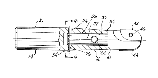
Referring to the drawings, a preferred tool holder comprises an
elongated steel body 10 and an elongated steel head 12. The body is
adapted to be mounted in the conventional manner on a milling machine
213440 4
4
base. Body 10 has a generally cylindrical inner end 14 and a
generally tapered outer end 16. The body has an outer annular shoulder
18 formed around the opening of an internal bore 20. Bore 20 has a
cylindrical inner surface formed about a longitudinal axis 22 which also
corresponds with the longitudinal axis of body 10 and head 12.
For illustrative purposes, bore 20 has a depth of about 2", slightly
less than one-half the overall length of body 10, which has a length of
about 4 1 /4". Bore 20 has a diameter of about 9/16".
A steel pin functions as a key 24. Key 24 has a length corre-
sponding to the thickness of body 10 and for illustrative purposes, has
a diameter of 3/16". Key 24 is permanently driven into an opening 26 in
the body. Opening 26 is formed along an axis that is transverse and
intersects longitudinal axis 22. The key is spaced from the bottom of the
bore.
The body also has a pair of fastener-receiving openings 28 and 30.
The two openings are each formed about parallel axis, and each
disposed at right angles to and intersecting longitudinal axis 22.
Openings 28 and 30 are longitudinally spaced about 5/8". The axis of
threaded opening 28 is spaced about 3/4" from the axis of key 24, as
best illustrated in Figure 4, and rotated 90° with respect to the axis
of the
key.
For illustrative purposes, referring to Figure 2, opening 30 is
2134404
formed along an axis 32 while the key opening is formed about an axis
34 which is at right angles to axis 32.
Head 12 has an enlarged outer end 36 formed with a pair of slots
38 and 40 for mounting indexable inserts 42 and 44. Each insert is
5 releasably fastened to the head by a fastener means 46. The inserts are
relatively flat, with cutting edges 50 and 52, respectively. The axis' of
fastener receiving openings 28 and 30 are disposed perpendicular to the
plane of the inserts.
Head 12 has an annular seat 54, and an elongated cylindrical
shank 56, received in bore 20. Shank 56 has a length less than the
depth of bore 20, and a diameter forming a snug sliding fit in the bore.
Referring to Figures 4 and 6, the inner end of the shank has a slot
58 for receiving key 24. The slot is transverse to the longitudinal axis of
the shank, has a depth greater than the diameter of key 24, and a width
closely corresponding to the diameter of key 24. The shank is inserted
into the bore until shoulder 18 of the body abuts shoulder 54 of the
head, at which time slot 58 receives key 24. Key 24 closely mates with
the slot, preventing any longitudinal rotation of the head with respect to
the body.
The shank has a pair of counter-drilled openings 60 and 62 which
are slightly offset from fastener receiving openings 28 and 30, respective-
ly, when the shank has been fully received in bore 20. A threaded
2134404
6
socket head fastener 64 is threadably received in opening 28, and a
second threaded socket head fastener 66 is threadably received in
fastener opening 30.
The two counter-drilled openings are identical except with respect
to their location along the shank. Openings 28 and 30 are located on
opposite sides of the shank, and the axis of each counter-drilled opening
is at right angles to the axis of key 24. A typical counter-drilled
opening and its fastener is illustrated in Figure 5. Counter-drilled
opening 60 has a concave, frusto-conical surface 68 adjacent the inner
end of fastener opening 28. The axis of counter-drilled hole 70 is offset
from axis 72 of fastener-receiving opening 28. This distance is somewhat
exaggerated in Figure 5 to show that the axis of each counter-drilled
opening is closer to shoulder 18 of the body than the axis of the
corresponding fastener receiving opening.
Fastener 64 has a rounded inner end 76 that slideably engages
frusto-conical surface 68. The arrangement is such that as fastener 64
is threadably inserted into opening 28, inner end 76 engages surface 68
to cam the shank toward the bottom end of the bore, thereby causing
shoulder 54 to tightly abut shoulder 18.
Similarly, the rounded inner end of fastener 66 slideably engages
the frusto-conical surface of counter drilled opening 62 to cam the shawl
toward the bottom end of the bore.
2134404
The diameter of the shank very snugly fits the internal surface of
bore 20, and shoulder 54 tightly abuts shoulder 18 in order to locate the
inserts in a proper cutting position when the head is replaced with a
different pair of inserts.
To assemble the tool holder, the inserts are mounted in the usual
manner on the outer end of the head. The shank is inserted in bore 20
until slot 58 is aligned with and receives key 24.
Threaded fasteners 64 and 66 are then screwed into their
respective counter-drilled openings to cam the shank until shoulder 54
abuts shoulder 18. The process is reversed, to remove the head.
Having described my invention, I claim: