Note: Descriptions are shown in the official language in which they were submitted.
Z1~4~~~
ANTI-EAVESDROPPING DEVICE
BACKGROUND OF THE INVENTION
Field of the Invention
This invention relates generally to anti-
eavesdropping equipment and communication equipment,
specifically it relates to an anti-eavesdropping
device.
-1-
~~3~4~8
Discussion of the Prior Art
Prior art communication devices, such as
telephone, radio, television and similar apparatuses
have not solved the problems of industrial, political
and military eavesdropping. Prior art anti-
eavesdropping devices have been capable only of
detecting the presence and location of some types of
eavesdropping equipment.
-2-
CA 02134408 2000-04-20
SUMMARY OF THE INVENTION
In accordance with an embodiment of the present
invention there is provided an anti-eavesdropping device
which comprises: a) a face mask for containing sound waves
emanating from a mouth of a first person; b) a headset for
containing sound waves entering into the ears of a second
person; c) a microphone in the face mask for converting the
sound waves into electric waves; and d) amplifier means in
- 3 -
CA 02134408 2000-04-20
the headset for converting the electric waves back into the
sound waves, the amplifier means being in cooperative
engagement with the microphone so that the two people can
engage in conversation, in which no sound will escape into
the environment to be detected in any way.
30
- 4 -
CA 02134408 2000-04-20
Further features of the invention will appear as
the description proceeds.
To the accomplishment of the above and related
objects, this invention may be embodied in the form
illustrated in the accompanying drawings, attention being
called to the fact, however, that the drawings are
illustrative only, and that changes may be made in the
specific construction illustrated and described within the
scope of the appended claims.
30
- 5 -
~13440~
BRIEF DESCRIPTION OF THE DRAWING FIGURES
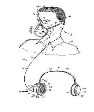
FIGURE 1 is a perspective view of the
invention showing the face mask worn on a person.
FIGURE 2 is a side view taken in direction
of arrow 2 in Figure 1 with parts broken away.
FIGURE 3 is an enlarged cross sectional
view taken along line 3-3 in Figure 1.
FIGURE 4 is an enlarged perspective view
taken in direction of arrow 4 in Figure 1 with parts
broken away.
-6-
DETAILED DESCRIPTION OF THE PREFERRED EMBODIMENTS
Turning now descriptively to the drawings,
in which similar reference characters denote similar
elements throughout the several views, Figures 1
through 4 illustrates an anti-eavesdropping device
10, which consists of a first structure 12 for
containing sound waves emanating from a mouth 14 of a
first person 16. A second structure 18 is for
containing sound waves entering into the ears of a
second person (not shown). A first mechanism 20 in
the first containing structure 12 is for converting
the sound waves into electric waves. A second
mechanism 22 in the second containing structure 18,
is for converting the electric waves back into the
sound waves, so that the two people can engage in
conversation, in which no sound will escape into the
environment to be detected in any way.
~i3~~o~
The first sound containing structure 12 is
a face mask 24. The second sound containing
structure 18 is a headset 26. The first converting
mechanism 20 is a microphone 28.
The second converting mechanism 22 consists
of an amplifier 30 that is electrically connected to
the headset 26. A power supply 32 is electrically
connected to the amplifier 30. A component 34 is for
electrically connecting the amplifier 30 to the
microphone 28.
The face mask 26 contains a flexible
covering 38, to fit over the mouth 14 and nose 40 of
the first person 16. A cushion 42 is on a periphery
of the flexible covering 38, to form an acoustic seal
about the mouth 14 and nose 40. A strap 44 extends
from the flexible covering 38, to fit about the head
46 of the first person 16. The strap 44 includes a
_g_
2i3440~
buckle 48 to make the strap 44 adjustable to fit
different sized heads 46.
The headset 26 consists of a pair of
headphones 47. An adjustable headband 49 extends
between the headphones 47, so that the headphones 47
will be supported against the ears of the second
person.
Each headphone 47 includes a housing 50
connected to one end of the adjustable headband 49.
A grille 52 is on the housing 50, to face one ear. A
small speaker 54 is within the housing 50 behind the
grille 52. A cushion 56 is on a periphery of the
housing 50 about the grille 52, to form an acoustic
seal about the ear.
The power supply 32 is a battery 58. A
receptacle 60 is mounted to one housing 50 opposite
_g_
2134~0~
from the grille 52, to hold the amplifier 30 and the
battery 58 therein. A lid 62 is hinged at 64 to the
receptacle 60, so that the battery 58 can be removed
and replaced when needed.
The electrical connecting component 34
consists of a first jack 66 on the flexible covering
38 of the face mask 24, electrically connected to the
microphone 28 therein. A second jack 68 on the
receptacle 60 is electrically connected to the
amplifier 30 therein. An elongate electrical cord 70
is provided, with a pair of plugs 72, 74 each of
which is connected to each end of the elongate
electrical cord 70. The plugs 72, 74 can engage with
the first jack 66 and the second jack 68.
An apparatus 76 is in the flexible covering
38 of the face mask 24, for allowing air to enter for
breathing, while preventing sound to leave therefrom.
-10-
2~3~~4~8
The breathing apparatus 76, as best seen in Figure 3,
is an elongated hollow tube 78 extending upwardly
from the flexible covering 38 of the face mask 24,
adjacent the nose 40 of the first person 16. The
elongated hollow tube 78 has a plurality of staggered
baffles 80, some of which extend downwardly while
others extend upwardly at an angle therein. The air
can enter the hollow tube 78, while the baffles 80
prevent sound from exiting the hollow tube 78.
The device 10 can also contain an on/off
volume switch. Other embodiments are also possible,
such as the face mask 24 covering only the mouth 14,
leaving the nose 40 to breathe naturally. The face
mask 24 can also cover the mouth 14, the nose 40,
face and head 46 of the first person 16, to contain
the sound waves. Earphones can be used instead of
headphones 47. A combination microphone-earphone can
be utilized to make a version that picks up sound
from the ear.
-11-
213448
The breathing apparatus 76 described above
is the preferred type to be utilized. Other kinds of
breathing apparatuses can also be used.
The function of transferring the electronic
message from the face mask 24 to the headphones 47
can also be done in other ways, such as by radio
transmission for longer distance communications, or
by using hollow tubes which conduct sound in place of
microphones, speakers and wires.
-12-
21~~~~~
LIST OF REFERENCE NUMBERS
10 anti-eavesdropping device
12 first sound containing structure
14 mouth of 16
16 first person
18 second sound containing structure
-13-
213~~08
20 first converting mechanism in 12
22 second converting mechanism in 18
24 face mask for 12
26. headset for 18
28 microphone for 20
30 amplifier
32 power supply
34 electrical connecting component
-14-
~~~~~o~
38 flexible covering
40 nose of 16
42 cushion on 38
44 , strap on 38
46 head of 16
47 headphone
48 buckle on 44
49 adjustable headband
-15-
2~~~~0~
50 housing
52 grille on 50
54 small speaker in 50
56. cushion on 50
58 battery for 32
60 receptacle
62 lid
64 hinge between 60 and 62
-16-
2134408
66 first jack on 38
68 second jack on 60
70 elongate electrical cord
72 , first plug on 70
74 second plug on 70
76 breathing apparatus in 38
78 elongated hollow tube
80 baffle in 78
-17-
213~~~
It will be understood that each of the
elements described above, or two or more together may
also find a useful application in other types of
methods differing from the type described above.
While certain novel features of this
invention have been shown and described and are
pointed out in the annexed claims, it is not intended
to be limited to the details above, since it will be
understood that various omissions, modifications,
substitutions and changes in the forms and details of
the device illustrated and in its operation can be
made by those skilled in the art without departing in
any way from the spirit of the present invention.
Without further analysis, the foregoing
will so fully reveal the gist of the present
invention that others can, by applying current
knowledge, readily adapt it for various applications
without omitting features that, from the standpoint
of prior art, fairly constitute essential
characteristics of the generic or specific aspects of
this invention.
-18-