Note: Descriptions are shown in the official language in which they were submitted.
D-20100 2134S9O
SYSTEMS AND PROCESSES FOR PYROLYZING CONTAMINANTS ON
FOUNDRY SAND AND COMBUSTING THE RESULTING GAS
FIELD OF THE INVENTION
The invention relates to systems and processes for
pyrolizing cont~m;n~nts on foundry sand and combusting
the gas resulting from the pyrolysis.
BACKGROUND OF THE lN V~N'l'lON
The foundry industry uses sand, such as silica,
chromite or olivine sand, extensively in forming molds
which are suitable for casting molten metals. In
forming the molds, the sand is combined with various
binding agents. Usually, the binding agents employed
are natural binders, such as linseed oil and bentonite,
and chemical binders, such as organic resins. The type
of the binding agents employed is dependent on the
desired molding properties. However, bentonite and
organic resin binders are widely utilized. Most of the
organic resin binders are based on phenolic and
furannic resins that form reticular structures under
the influence of a catalyst together with or without
the application of a moderate temperature.
The foundry industry recycles large quantities of
spent sand having binder residues. Most often, the
spent sand is recycled after being subject to a
mechanical/attrition treatment followed by a screening
step. The mechanical/attrition treatment allows to
remove or screen out the binder residues that have been
broken down to extremely fine particles. Such a
treatment, however, also causes the sand grains to
break and erode, thus resulting in removing or
screening out large quantities of the sand with the
binder residues. Typically around 20~ of the sand is
lost in such an operation. That is, millions tons of
the sand are disposed worldwide annually as a waste.
D-20100 213 4 5 9 0
Even though a large quantity of the disposed spent sand
contains bentonite (referred to as "green sand") and
may be harmless to the environment, it is often
combined or mixed with spent sand containing organic
binders due the employment of bentonite and organic
binders for making the different parts of a mold and/or
due to the complexity of the foundry industry's
operation. The disposed spent sand having the organic
binders is normally hazardous to the environment.
To avoid the inefficiency and environmental hazard
associated with the above recycling method, several
thermal sand reclamation processes involving a fluid
bed have been proposed. In these processes,
electricity or natural gas is used for auxiliary
heating while air is normally used as a fluidizing
medium and as a means for burning organic residues
present on the sand. These processes are useful for
continuously treating large quantities of sand
containing substantially identical binders and having
substantially identical granulometry. However, they
are neither effective nor efficient in treating
different sands, i.e., sands having different
granulometry and different binders, sequentially or in
mixture since different operating parameters are needed
for different sands. Moreover, crushing the spent
(used) sand clods to very fine mesh for the fluidized
bed treatment is a process handicap.
Consequently, WO 91/08068 has proposed a different
thermal process for roasting foundry sand. Initially,
the cont~mi n~ ted spent sand is charged into a rotatable
furnace. The furnace rotates about an axis at an angle
ranging from about 5 to about 15~, measured from
vertical. Oxygen is injected at the bottom of the sand
batch and diffuses throughout the sand batch. In the
meantime, a flame front provided from a burner on the
~-20100
213l590
top of the furnace is directed to a upper surface of
the sand batch. After the flame from the burner is
ceased, oxygen is continuously injected to cause a
progressive descent of the flame front until complete
combustion of the contAm;nAnts has taken place. This
thermal process, however, may suffer from certain
disadvantages. First, the flame front may not descent
progressively toward the bottom of the sand batch, when
the sand contains limited burnable contAm;nAnts. The
flame front from the top may be able to co-mbust
cont~m;nAnts on the upper layer of the sand batch, but
may not be able to reach the bottom layer of the sand
batch. Second, the desired temperature uniformity may
not be obtained since the flame from the burner, i.e.,
the tip of a flame, contacts only a small area of the
upper layer of the sand batch. A certain portion of
the sand batch, especially those at the bottom, may not
be subject to the flame front and may still have
contAm;nAnts when the operation is ceased. Third, the
sand grain may be fractioning due to thermal shock
since the sand grain is subject to rapid heating as the
fire front progresses downward. The body of the sand
batch, for example, may be subject to thermal shock
because it does not appear to be preheated. Finally,
an off gas containing substantial amounts of the
partially pyrolized organic contAm;nAnts and CO may be
released to the atmosphere since the injection rate for
oxygen diffusing through the layer of the spent sand
batch is normally kept at a pretty low level to avoid,
among other things, channelling and local fluidization
of the sand batch.
It is an object of the invention to reduce or
eliminate the presence of CO and partially pyrolized
hazardous organic matter in the off gas exiting a
foundry sand roasting rotary furnace.
D-20100
2134590
It is another object of the invention to promote
temperature uniformity within a rotary furnace, i.e.,
the head space and sand batch within a rotary furnace,
during pyrolysis.
It is yet another object of the invention to
provide ways to control the temperature within a rotary
furnace during pyrolysis and co-mbustion to m;n;m;ze any
alteration of the sand grain structure.
It is a further object of the invention to reduce
dust entrainment in the off gas exiting a rotary
furnace.
It is an additional object of the invention to
provide a thermal process useful for treating different
sands effectively and efficiently.
It is an additional object of the invention to
provide a thermal process useful for treating and
decont~m;n~ting spent sand that has to be disposed of,
such as sand fines and dust, so that such a disposal is
harmless to the environment.
It is an additional object of the invention to
allow the use of an iron melting rotary kiln for
pyrolyzing spent sand and com~busting the resulting gas
during dwell times.
SUMMARY OF THE INVENTION
According to one e-m-bodiment of the invention, the
above objectives and advantages are achieved by a
process for roasting foundry sand contaminated by
organic matter in a container capable of rotating about
an axis, said process comprising:
(a) feeding said foundry sand contaminated with
organic matter into said container;
(b) adjusting said container so that said axis is
at an angle ranging about 0 to about +10~, measured
from horizontal;
D-20100
2134590
-- 5
(c) rotating said container about said axis; and
(d) firing at least one flame with excess oxygen
in said container at an angle ranging from about 0 to
about +30~, measured from horizontal or said axis, to
produce an off gas cont~;n;ng oxygen and roasted
foundry sand. The amount of said excess oxygen
introduced into said container is such that pyrolysis
products evolving from the sand batch as the
cont~m;n~nts are heated up and are completely co-mbusted
in the container head space. This is achieved when
said off gas leaving the outle port of the container
contains at least 2~ by volume oxygen. This desired
oxygen concentration in the off gas is maintained by
analyzing the oxygen content of the off gas with an off
gas oxygen analyzer and then adjusting the oxygen flow
accordingly. The firing rate of an oxidant containing
an oxygen concentration greater than about 25 ~ by
volume and fuel used to produce at least one flame and
excess oxygen is controlled to cause to form
recirculating matter and/or reduce particle entr~;nment
in the off gas. Upon ceasing the firing of at least
one flame and excess oxygen, oxidant may be dispersed
at the bottom of said foundry sand in order to
completely combust any hazardous organic matter and/or
any carbon residues left on the sand. The carbon
residue is formed as a result of pyrolyzing the organic
matter on the spent sand with the oxygen-fuel burner.
According another embodiment of the invention, the
above objectives and advantages are achieved by a
combustion system capable of roasting foundry sand
containing cont~m;n~nts, said combustion system
comprising:
(a) a rotary kiln comprising a container, a
circular frame for surrounding and supporting said
container so that said container is capable of rotating
D-20100
213~590
- 6
about an axis, a means for rotating said container
coupled to said circular frame and a base pivotally
coupled to said circular frame, wherein said container
has, at least one side wall, at least one front wall
defining an inlet port and at least one back wall
defining an outlet port;
(b) a means for combusting foundry sand selected
from the group consisting of a porous plug for
distributing oxidant into said container or an oxygen-
fuel burner for firing a flame and excess oxygen into
said container, said means for combusting being
designed to be fitted into and/or fastened to said
inlet port of said container; and
(c) an off gas oxygen analyzer in fluid
comml~n;cation with said outlet port of said container.
Optionally, post treatment systems for the off
gas, such as a post-combustion furnace, a flue gas
cooling device, filtering means and/or a pollutant
removing means may be provided.
As used herein the term "cont~m;n~nts" means any
substance, such as chemical or organic binders, on
foundry sand, which is hazardous to the environment.
As used herein the term "organic matter" means any
organic substance, such as phenolic and furannic
resins, on foundry sand.
As used herein the term "different sands" means
sands having different binding agents and/or sands
having different granulometry.
As used herein the term "at least one oxygen-fuel
burner" means one or more burners, which fires fuel and
an oxidant having an oxygen concentration of greater
than 22~ by volume, preferably greater than 25~ by
volume, more preferably greater than 50~ by volume, to
produce a flame.
D-20100 213459 0
As used herein the term "excess oxygen" means the
amount of oxygen sufficient to cause the off gas
exiting a rotary kiln to contain oxygen.
As used herein the term "dwell time" means a
period in which a rotary kiln is not used to melt
metals.
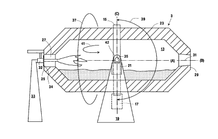
BRIEF DESCRIPTION OF THE DRAWINGS
Figure 1 is a diagrammatic view of a spent sand
treatment system comprising a rotary kiln, an off gas
oxygen analyzer, a post combustion furnace, a flue gas
cooling device, a filtering means, and a pollutant
removing device, which illustrates one embodiment of
the invention.
Figure 2 is a cross-sectional view of a rotatable
kiln having an oxygen-fuel burner illustrating one
embodiment of the invention.
Figure 3 is a cross-sectional view of a rotatable
kiln having a porous plug illustrating one embodiment
of the invention.
DETAILED DESCRIPTION OF THE lNV~NllON
Referring to Figure 1, a spent sand treatment
system (1) is diagrammatically illustrated. The spent
sant treatment system (1) includes a rotary kiln (3),
an oxygen analyzer (5) an off gas combustion furnace
(7), a flue gas cooling means (8), a filtering means
(9) and a pollutant removing system (11) for removing,
e.g. SO2. The rotary kiln (3), as illustrated in
Figures 2 and 3, generally comprises a container (13),
a circular frame (15), a first rotating means (17), a
base structure (19), and a second rotating means (21).
The container (13) has at least one side wall (23), at
least one front wall (25) defining an inlet port (27)
and at least one back wall (29) defining an outlet port
(31). The inlet port (27) of the container (13) is
D-20100
q D
designed to readily accommodate or readily remove a
porous plug (30) and at least one oxygen-fuel burner
(32). This container (13) is surrounded and supported
freely rotatably by the circular frame (15). The
circular frame (15) is equipped with rollers on its
internal face to match with a rolling band fitted at
the outside of the container side wall (23). This
circular frame ( 15) is in turn supported by the base
structure (19). Specifically, the base structure (19)
is connected pivotally to the circular frame (15) via
pivot pins (35), such as two trunnions. The first
rotating means (17), such as an electrical motor, may
be coupled to the outsid of the circular frame (15) in
order to rotate the container (13) in the direction of
an arrow (37) during foundry sand roasting. The second
rotating means (21), such as a pneumatic or electric
rotating device, may be attached to the base structure
(19) in order to tilt or adjust the container (13) in
the direction of an arrow (39) by means of a seal (42)
located on the circular frame trunnions. This allows
the container (13) to be tilted about 180~ in the
vertical plane (C).
Initially, at least a portion of foundry sand,
which has been contaminated with chemical or organic
matter, e.g, organic resin binders, is provided. Such
sand may be crushed to the desired particle sizes. The
foundry sand, which may or may not have been crushed,
is loaded into the container (13) through the inlet
port (27) using a hopper (not shown). The container
(13) may be made with chemical and temperature
resisting materials, such as refractory materials,
alloys, steel or stainless steel. Specifically, the
container shell may be made with heat resisting steel
while lining its internal face with refractory
materials. This container (13) is tilted or adjusted
B-20100 CA 02l34~90 l997-l2-l7
90 that an axis (A) of the container (13) is at an
angle ranging from about 0 to about +10~, preferably 0
to about +5~, measured from the horizontal plan (B).
The tilting or adjustment of the cont~iner (13) is
accomplished by actuating the second rotating means
(21).
After or before tilting the cont~;ner (13), at
least one oxygen-fuel burner (32) is inserted into the
inlet port (27). At least one oxygen-fuel burner (32)
which may be hanging or attached to an outside
structure (33), is pushed into its firing position by
means of, e.g., a pneumatic jack. The oxygen-fuel
burner is free st~n~;ng inside of the inlet port (27).
A plate (34) may be mounted to seal the inlet port (27)
tightly in order to prevent excess atmospheric air from
entering the container (13) during the operation.
At least one oxygen-fuel burner (32) employed may
be any conventional oxygen-fuel burners capable of
providing a flame and excess oxygen, e.g., about 50~ to
about 180~ greater than a stoichiometric amount of
oxygen. The conventional oxygen-fuel burners generally
have at least one passageway for firing an oxidant
having an oxygen concentration of at least about 22~ by
volume, preferably at least about 25 ~ by volume, and
at least one passageway for firing fuel. The oxidant
passageway or passageways should be capable of firing
at least about 50 ~ greater than, preferably at least
100 ~ greater than, a stoichiometric amount of oxygen,
e.g., the amount sufficient to produce a flame (react
with the fuel) and excess oxygen. The preferred
oxygen-fuel burners are aspirating oxygen-fuel burners
such as those described and/or claimed in U.S. Patent
No. 4,541,796 and U.S. Patent No. 4,907,961-Anderson.
These aspirating burners have particularly designed
oxygen passageways
D-20100
2134590
- 10 -
and a fuel passageway such that recirculating matter
(41) can be formed upon firing the oxidant at a certain
velocity and such that excess oxygen can be introduced
easily. The formation of the recirculating matter (41)
within the container (13) is found to promote
temperature uniformity.
The oxygen-fuel burner (32) provided is positioned
to direct a flame above the foundry sand in the
container at an angle ranging from about 0 to about
+30~, preferably about 0 to +10~, more preferably about
0 to +5~, measured from the horizontal plan (B) or the
axis (A). As the direction of the flame is closer to
the horizontal plan (B) or the axis (A), flame energy
can be efficiently and effectively utilized to burn
pyrolysis gas evolving from the sand batch uniformly
above the sand surface, hence promoting complete
burning as well as temperature uniformity within the
container (13). In other word, it is most desirable to
fire a flame parallel to the axis (A) of the container
(13) or the surface of the container (13). Of course,
this may require the inlet port (27) defined in the
front wall (25) to be located just above the surface of
the foundry sand in the container, e.g., the center of
the front wall (25).
Once the oxygen-fuel burner (32) is appropriately
positioned or oriented, oxidant and fuel, such as
natural gas, are delivered to the oxygen-fuel burner
(32). The oxygen-fuel burner (32) may be lighted using
a remote control ignition/control device (not shown) in
order to produce a flame by combusting the fuel in the
presence of oxidant. The firing rates of the fuel and
oxidant are controlled so that the resulting off gas
leaves the container (13) at a velocity below 3 meters
per second, thus reducing or preventing dust
entr~;nment. Optionally, the firing rate of oxidant
D-20100
4 5 ~ ~
may also be adjusted to form the recirculating matter
(41) in order to promote temperature uniformity within
the container (13). Normally, the oxidant is fired at
a velocity of about 200 meters/second to about 300
meters/second to form the recirculating matter (41).
The oxidant employed has an oxygen concentration of
greater than 22 ~ by volume, preferably greater than 25
~ by volume, more preferably greater than 50 ~ by
volume. It is most desirable to use technically pure
oxygen.
The amount of oxidant delivered is such that the
oxygen-fuel burner (32) fires a flame and excess oxygen
into the container (13). The amount of excess oxygen
normally causes the off gas, i.e., the gas formed from
combusting pyrolysis gas emanating from the sand batch,
to contain at least about 2 ~ oxygen by volume or the
resulting container atmosphere to contain at least
about 2 ~ oxygen by volume. In order to obtain such an
off gas or an atmosphere, the amount of oxidant
delivered to the oxygen-fuel burner (32) typically
provides about 50 ~ to about 180~ over a stoichiometric
amount of oxygen for producing a flame or combusting
the fuel. For instance, the fuel, such as natural gas,
may be delivered at a flow rate of about 15 Nm3/hour to
about 60 Nm3/hour per ton of the foundry sand whereas
the oxidant, e.g., technically pure oxygen, is
delivered at a flow rate of about 45 Nm3/hour to about
240 Nm3/hour per ton of the foundry sand. The amount of
oxidant delivered can be controlled or regulated to
maintain the desired oxygen concentration within the
container atmosphere, i.e., the desired off gas
containing at least about 2 ~ oxygen by volume.
Initially, the oxygen content of the off gas leaving
the container (13) through the outlet port (31) or the
oxygen content of the container atmosphere is analyzed
D-20100 2134590
with the oxygen analyzer (5), such as a close-coupled
extractive analyzer that aspirates a sample out of the
furnace and passes it on a probe, eg., a zironium oxide
probe. The konwn close-coupled extractive analyzer is
sold under the Trademark "THERMOX " and "CASA ". The
oxygen analyzer (5) may be connected to/ a conduit
which is in fluid commnn;cation with the outlet port
(31) to analyze and transmit the oxygen concentration
level in the off gas or the container atmosphere.
Based on the analyzed and transmitted concentration
level, the amount of oxidant delivered is adjusted or
regulated manually or automatically to maintain the
desired oxygen concentration within the container
atmosphere or the off gas. Preferably, the adjustment
to the oxidant delivery rate or the oxidant firing rate
may be made relative to time laps or made using an
automatic control loop that adjusts the oxygen to the
fuel ratio from the readings of the off gas oxygen
analyzer (5). By maintaining the desired oxygen
concentration in the container atmosphere, i.e., in the
off gas, any hazardous products of incomplete
combustion or pyrolysis of the cont~m;n~nts are
prevented or substantially prevented from leaving the
container (13) with the off gas, e.g., below the
m~x;mllm tolerable limits. Moreover, the CO content in
the off gas is substantially reduced, e.g., below the
maximum tolerable limits.
During the firing of the flame from the oxygen-
fuel burner (32), the container (13) is rotated about
the axis (A) which is at an angle ranging from about 0
to about +10~, preferably 0 to about +5~, measured from
the horizontal plan (B) (hereinafter referred to as
"horizontal"). The rotation speed of the container
(13) is controlled or regulated by adjusting or
controlling the first rotating means (17). The
D-20100
5 Q ~
rotation speed of the container (13) is maintained at
normally less than about 5 revolutions per minute,
preferably less than about 2 revolution per minute.
Commonly, the firing of the flame and excess oxygen,
together with the rotating of the container (13), is
carried out for a period of about 20 to about 40
minutes. It is possible to fire the flame and excess
oxygen and to rotate the container (13) for a period of
less than 20 minutes or greater than 40 minutes,
depending on the amount of the foundry sand treated,
the size of the container (13).
Once the cont~m;n~nts are substantially pyrolyzed
e.g., once the organic matter, such as phenol, is
reduced to below 1 mg of the organic matter/ton of the
foundry sand, the firing of the flame and the excess
oxygen, as well as the rotation of the container (13),
is ceased. The duration of the firing and rotation may
also be adjusted so that the temperature at a point of
cessation is about 500 to about 800 ~C. The adjustment
of the temperature enhances subsequent combustion of
any r~m~;n;ng uncombusted partially pyrolyzed hazardous
organic matter and/or any carbon residues that have
resulted from the pyrolysis. The temperature at the
point of cessation is inversely related to the amount
of the remaining organic matter and the resulting
carbon residues to be burned at the subsequent
combustion stage.
After cessation, the oxygen-fuel burner (32) is
removed from the inlet port (27). Then, the porous
plug (30) is inserted or screwed into the inlet port
(27). If it is not screwed into the inlet port (27),
it is fastened, e.g., bolted, coupled or attached, so
that the inlet port (27) of the container (13) is
tightly sealed. The porous plug (30) is made with
chemical and temperature resisting materials, such as
D-20100
2134590
- 14 -
refractory materials, alloys, steel or stainless steel.
The porous plug (30), for example, may be a fabricated
block of castable refractory with a plurality of
embedded metal or alloy tubes having an internal
diameter in the rang of about 0.5 to about 3 mm,
preferably about 0.5 to about 1 mm.
To the porous plug (30), an oxidant source (43) is
connected via a flexible hose (45). The flexible hose
(45) is coupled to the base plate of the porous plug
(30) preferably using a rotary joint. Upon connecting,
oxidant is supplied from the oxidant source (43) to the
porous plug (30). The amount of oxidant supplied is
controlled to provide about 40 to about 160 Nm3 of
oxygen/hour per ton of foundry sand to burn any
remaining organic matter and/or any carbon residues,
namely about 0.5 ~ to about 2.0 ~ by weight of the
organic matter and/or elemental carbon based on the
total amount of the foundry sand, organic matter and
carbon residues. As the oxidant is emitted from the
porous plug (30), the container (13) is tilted or
adjusted with the second rotating means (21) so that
the axis (A) of the container is at an angle ranging
from about +1 to +30~, preferably from about +5 to +25~,
measured from the vertical plan (C) (hereinafter
referred to as "vertical"). Subsequent to the tilting,
the oxidant emitting from the porous plug (30) is
directed at an angle ranging from about +1 to +30~,
preferably from about +5 to +25~, measured from the
vertical plan (C) (hereinafter referred to as
"vertical"), from the bottom of the foundry sand. The
porous plug (30) produces effective dispersion of
oxidant through out the sand batch, thus effectively
combusting the left over carbon residues. The porous
plug (30) may be even more effective as the size of the
porous plug (30) increases. In the meantime, the
D-20100
2134S9O
- 15 -
container (13) is rotated about the axis (A) which is
at an angle ranging from about 0 to +30~, preferably
from about +5 to +25~, measured from vertical.
~otating the container (13) about the axis,
particularly the preferably axis, together with the use
of the porous plug (30) in a particular manner,
enhances dispersement and percolation of the oxidant.
It is understood that any gas distributors less
effective than or equivalent to the porous plug (30)
may be used in lieu of the porous plug (30).
Optionally, gas distributors or baffles may be used in
lieu of the porous plug (30) to blow oxidant at a
sufficient flow rate to fluidize and combust the
foundry sand in the container (13). This fluidized
treatment may require the container (13) to be modified
accordingly (higher head space, means for preventing
excessive dust entrainment, etc...).
The oxidant is normally distributed throughout the
foundry sand batch in the container (13). The oxidant
may be air, an oxygen enriched air or technically pure
oxygen. This oxidant is continuously or intermittently
fed into the container (13) until the organic matter
and/or carbon residues are completely combusted.
Usually, the oxidant injection rate is adjusted to
retain the end temperature of about 600 to about 800 ~C
and to complete the treatment (e.g., loss of ignition
below 0.5~) in a period of about 15 to about 30
minutes. The timing and end temperature ensure
complete combustion of the hazardous organic matter and
carbon residue (e.g., loss of ignition below 0.5~).
Upon complete combustion, the container (13) is tilted
and the oxidant flow is ceased. The resulting hot
treated sand is than poured through the outlet port
(31).
D-20100
2134~90
- 16 -
During the combustion of the contAm;nAnts, e.g,
carbon residues CO and possibly hazardous organic
matter, the off gas leaves or exits the container (13).
The off gas may be treated in the post combustion
furnace (7) to further reduce the carbon monoxide
content and the organic matter (if present) therein.
The off gas can also be cooled in a flue gas cooling
means (8) and then filtered in the filtering means (9)
to remove any dust or particulates therein. Moreover,
a pollutant treating means (11), such as adsorbents,
getter materials or a condenser unit, may be used to
treat the off gas. It is understood that the post
combustion furnace (7), the cooling means (8), the
filtering means (9) and the pollutant removing device
(11) can be employed alone as an off gas post
treatment, or in a different sequence. It is also
understood that the post combustion furnace (7), the
cooling means (8), the filtering means (9) and the
pollutant removing device (11) may not be employed.
The following example serves to illustrate the
invention. It is presented for illustrative purposes
and is not intended to be limiting.
BXAMPLE
The rotary kiln (3) illustrated in Figures 2 and 3
was used to treat about 1.4 ton of foundry sand
contaminated by phenolic resins. About 1.4 ton of this
foundry sand was loaded into the container (13).
Subsequent to the loading, an oxygen-fuel burner (32)
was installed in the inlet port (27) of the container
(13). The container (13) was then tilted so that its
axis (C) was at an angle of about 0~, measured from
horizontal. The container (13) was rotated about its
axis at about 1 revolution per minute as the oxygen-
fuel burner (32) fired a flame and excess oxygen. The
flame and excess oxygen heated and pyrolized the
r~-20100 2134590
- 17 -
phenolic resins on the foundry sand for about 29
minutes. During this period, natural gas (fuel) was
delivered to the oxygen-fuel burner at about 25
Nm3/hour. Oxygen, however, was delivered initially at
about 120 Nm3/hour for about 5 minutes and subsequently
at about 140 Nm3/hour for 24 minutes. Recirculating
matter (41) was formed to promote temperature
uniformity. The sand had an estimated temperature of
about 600 ~C by the end of thid period. The total
amount of the fuel consumed per ton of foundry sand was
about 8.6 Nm3 while the total amount of the oxygen
consumed per ton of foundry sand was about 47.1 Nm3.
This low fuel consumption was believed to be partly due
to using a well soaked container (13) at the time the
foundry sand was loaded, i.e., the foundry sand was
loaded one hour and forty five minutes after the
container was used for melting iron. Moreover, dust
entr~;nme~t in the resulting off gas in the container
(13) was m; n; m; zed.
After terminating pyrolysis of the phenolic resins
with the oxygen-fuel burner (32), the oxygen fuel
burner in the inlet port (27) was replaced with a
porous plug (30). The porous plug (30) was mounted in
the inlet port (27) and tightly sealed the front wall
(25). This porous plug (30), which was a fabricated
block of castable alumina refractory with 10 embedded
copper tubes having an internal diameter of about 2.76
mm, was in fluid comml~n;cation with an oxygen source
(43) through a flexible hose (45). The container 13
was then tilted so that the axis (A) of the container
(13) was at an angle of about 0~, measured from
vertical, i.e, in the vertical position. The container
(13) was rotating about the axis (A) as the oxygen fed
to the porous plug (30) was dispersed to the bottom of
the foundry sand. The container (13) constantly
~-20100 2134~90
- 18 -
rotated clockwise and counterclockwise about its axis
(A) since no rotary joint was used to fit the flexible
hose (45) to the base plate of the porous plug (30).
At this vertical position, the oxygen dispersed was not
percolating smoothly through the foundry sand.
Consequently, after about two minutes, the container
(13) was tilted again so that the axis (A) was at an
angle of about 20~, measured from vertical, e.g., in
inclined position. The container (13) constantly
rotated clockwise and counterclockwise about its axis
(A) as oxygen was constantly dispersed. The oxygen was
introduced initially at about 103 Nm3/hour for a period
of about 3 minutes, and then at about 88 Nm3/hour for a
period of about 31 minutes. The amount of oxygen
consumed per ton of the foundry sand is about 31.4 Nm3.
The estimated temperature within the container (3) was
about 900 ~C by the end of this treat~ent. After the
treatment, the container (3) was tilted to pour the
treated foundry sand into a collecting or conveying
means. The resulting sand was analyzed for its
phenolic content and its structure. While the loss on
ignition (LOI) was about 0.01%(the LOI was reduced from
4.95~ on the spent sand to be treated to 0.012~ after
the treatment), granulometry rankings indicated that
the sand structure was not substantially changed
(Average Finesse Size (A.F.S.) index was 63.95 just
before the treatment but was 61.21 after the
treatment).
Although the invention has been described in
detail with reference to certain embodiments, those
skilled in the art will recognize that there are other
embodiments of the invention within the spirit and
scope of the claims.