Note: Descriptions are shown in the official language in which they were submitted.
_ 1
AUTO-IGNITION DETECTION METHOD
FIET~D OF THE INVENTION
The present invention generally relates to a
automotive ignition system for an internal combustion
engine. More particularly, this invention relates to a
coil-~n-plug ignition transformer which is capable of
being fired ~,caording to an algorithm to perform
vari~us engine diagnostic procedures. The spark plug
mounted ignstion system of the present invention
ther~fore operates as a feedback element of the engine
control system.
BACJKGROUND AND SiTMMARY OF THE INVENTION
In order to initiate combustion of an
air/fuel mixture within an int~rnal combustion engine,
a spark'ignition system geaaerates a high voltage arc
across the~spark plug electrodes at the appropriate
time in the,engine operating cycle. The onset of the
arc across the spark plug gap is timed to occur at a
predetermined number of decrees of crankshaft
rotation, usually before the piston has reached top
dead center (TDC).
If the spaxk tinning is properly yet, th~~
combustion process initiated by the spark plug action
will cause a pressure increase to dev~lop within the ,
combustion chamber that will peak dust shortly after
TDC dtnring the,pistan's power stroke. If the spark is
initiated too late in the operating cycle (retarded
~1~~~1~
2
timing). the pressure developed within the combustion
chamber will not be efficiently converted by the engine
into work. On the other hand, if the spark is
initiated too early in the operating cycle (advanced
timing), extremely high and potentially damaging
pressures and temperatures may result. The pressure
and temperature increases associated with advance
timing are also not efficiently converted by the engine
into a useful work output.
Excessive advanced timing can also lead to
the occurrence of several other types of combustion
chamber phenomena. One such phenomena is auto-ignition
of the end gases and another is pre-ignition.
Auto-ignition is a condition where the end
gases (the unburnt portion of the fuel-air mixture
initially ignited by the movement of the flame front)
explode spontaneously as a result of the cylinder
temperature and pressure becoming too high for the type
of fuel being burned in the engine. In response to the
sudden release of energy, the cylinder temperature
dramatically increases and the cylinder pressure
,fluctuates, alternately rising and falling, as a
pressure wave travels back and forth across the
combustiowchamber. When caused by auto-ignition of
the end gases, the rapid pressure and temperature
fluctuations are seen to occur after TDC. If the rate
at which energy is released through auto-ignition is
high enough, the exploding gases will cause the
cylinder walls to vibrate resulting in audible engine
~, , .~
noises, including the distinctive sound~known as
"pingingn.
Many engine developers believe that a mild
degree of auto-ignition is desirable because it
generates turbulence within the combustion chamber,
which hastens the combustion process, at a critical
time when the normal flame kernel is in the process of
being quenched. Slight auto-ignition has also been
~~.~~~1~~
-
found to reduce the amount of unburnt hydrocarbons
remaining after the completion of the spark-triggered
ignition process. By utilizing the energy released
when the hydrocarbons are burned during mild auto-
s ignition, it follows that lower hydrocarbon emissions
and improved fuel economy can be realized.
Because of the benefits stated above, among
others, engine designers often seek to calibrate
ignition systems so that the spark advance is close to
the threshold of auto-ignition. However. excessive
auto-ignition must be avoided since it leads to higher
combustion chamber temperatures and is countex
productive. In fact, these elevated temperatures can
heat the spark plug electrodes to the point where they
will initiate the combustion process independently of
the occurrence of a spark. This phenomena is pre-
7.gn3.tl.On.
Pre-ignition, which can cause significant
engine damage including perforation of the piston, is
characterized by the occurrence of extremely high
cylinder temperatures and pressures near TpC. The
audible sound associated with pre-ignition is produced
by the action of auto-ignition and, when extrem~,
referred to as "knock". Generally, it can be stated
that auta-ignition leads to pre-ignition and,
subsequently, that pre-ignition leads to further auto-
ignition.
A number of factors influence the spark
timing threshold which generates auto-ignition. Some
.. , , ;; ."
of these factors include, inlet~air temperature, eiagine
speed, engine load, air/fuel ratio and fuel
characteristics. Because accurate control of the spark
timing is a significant contributor to engine
performance, numerous types of engine control systems
have been developed. These control systems typically
employ a microprocessor based closed-loop spark timing
control system which simultaneously measures a number
~~.~~~1~
of parameters, such as exhaust composition, coolant
temperature. and the occurrence of spark knock via
transducers. The resulting data is then processed to
set the engine timing near a predicted auto-ignition
threshold.
The knock detectors typically used in engine
control systems are piezoelectric transducers which
sense the intense vibration caused by spark knock.
When used in the environment of an internal combustion
engine, however, these transducers may riot be selective
enough to distinguish the alight vibration produced by
incipient auto-ignition over thg normal amount of
engine vibration. For this reason, these detectors are
typically not capable of sensing, particularly at high
engine speeds, the threshold of auto-ignition. An
engine control system is therefore needed which is
capable of detecting incipient auto-ignition
and which enables more precision in setting the spark
timing in a closed-loop syatenn.
Other characteristics found in ignition
systems and considered to be undesirable include, but
are not limited to: excessive spark plug electrode
wear; the inability to fire fouled spark plugs; poor
cold weather starting; poor exhaust emissions during
cold engine starting and running; the remote generation
of high voltages in the engine compartment by the
ignition system; the routing and distribution of high
voltages over considerable lengths of ignition wire;
and the generation of,aignificant amounts of electra-
magnetic radiation within'and around tho ignition
system, as well as the vehicle, during op~ration of the
engine.
It is therefore an object of the present
invention to provide an engine control and ignition
system which overcomes the limitations and
disadvantages of known syst8ms.
It is also~an object of this invention to
~~a~~~~~
- 5 -
provide an ignition system which is capable of
performing various engine diagnostic procedures so as
to operate as a feedback element of the engine control
system. In particular, the invention operates as a
non-invasive combustion chamber monitor through the
utilization of the ignition transformer and the spark
plug as the feedback elements.
The present invention has as further objects
the providing of a method far determining engine load,
a method for detecting engine misfire and a method for
detecting auto-ignition of the end gases.
Another abject of the invention is to provide
a coil-on-plug ignition transformer which is capable of
charging, firing and refiring the spark plug at short,
repeatable intervals as programmed into the engine
control system.
One feature of this inventian is that it
eliminates the various problems associated with the
distribution of high voltages throughout the ignition
system. Another feature of the present invention is
that it reduces the amount of electro-magnetic
radiation generated by the ignition system around the
~ngine and the vehicle itself.
Reduced spark plug electrode wear is another
feature as well as the ability to fire badly fouled
spark plugs.
A still further feature of the invention is
enhanced cold weather starting capabilities of an
internal combustion engine and the minimization of
I ' i i
exhaust emissions which oceur during cold starting'and
running. A related feature is the extension of the
air/fuel ration toward the lean limit which helps to
further reduce emissians and improve fuel economy
during normal engine operation.
SUMM~rRY OF THE IPNENTION
Recent research, some of which has been
performed by the assignee of the present invention, has
~l~~g~.~
-6_
indicated that combustion within an internal combustion
engine can be improved by initiating the burning
process with a spark of the type known as a breakdown
discharge. The breakdown spark has characteristics
quite different from those generated by conventional
automotive ignition systems and responds differently to
different conditions within the combustion chamber.
This realization has led to the development of the
present invention, an ignition control system having
components which are capable of exploiting the
characteristics of the breakdown spark so ass to enable
the performance of various engine diagnostic procedures
using the spark plug itself as a feedback element of
the engine control system.
The ignition process has been characterized
as consisting of three distinct phases; the breakdown
phase; the arc phase and the glow phase. The initial
phase. the breakdown phase, is characterized by high
current (typically 50 - 200 amperes (A)) which results
from the energy stored in the spark plug capacitance
(typically 10 - 15 picofarad (pF)) discharging through
the arc. The breakdown phase typically lasts less
about a nanosecond (ns). The second phase, the arc
phase, occurs when the arc current is between 0.1 and
1.0 A and the arc voltage is about 180 volts (v). The
discharge current remains in the arc phase for
approximately 100~CS. The glow phase occurs when the
arc current drops below 0.1 milliamperee (mA) and the
voltage across the spark plug electrodes goes to 500v.
These three'phases. the break3own,~arc and
glow phases, have been found to reliably initiate
combustion of the air/fuel mixture when the air/fuel
ratio ie respectively twenty-one to one, eighteen to
one and sixteen to one. If the breakdown phase is
exploited, it follows that the lean limit can be
extended and numerous benefits realized.
As mentioned above, the present invention
zl.~~~~1~
details an ignition and engine control system which is
not only capable of firing the spark plug, but which is
also capable of performing diagnostic functions.
Specifically, one aspect of the present invention
details the ignition and engine control system itself.
Another aspect details the methods for perforaning
various diagnostic procedures: A further aspect of
this invention is a low impedance ignition transformer,
mounted directly on the spark plug, which enables both
of the above. The transformer's low impedarace augments
the capabilities of the engine control system's
microprocessor unit (MPU) making it gossible for the
MPU to use the agark plug to monitor a number of engine
conditions including misfire, auto-ignition and engine
load.
The ignition and engine control system of the
greaent invention includes six principal components not
counting the engine itself. These are an engine
controller (which has inputs that monitors various
engine parameters), a MPU (which is programmed to carry
out various routines based on the inputs to the engine
controller), ignition or coil driver circuit, an
ignition transformer, a spark plug and current
discharge detection circuitry, all of which are
described in greater detail below.
The design of the ignition transformer
provides for a short charging time and an intense
secondary current of short duration (approximately 0.5-
lA,.decaying to zero in approximately 100~CS) that
reliably initiates stable combustion. This is achieved
while deriving energy directly from the vehicle's 12v
power supply and eliminating the need for an expensive
l2vDC to 250vDC converter.
Because of the intensity and duration spark,
as well as the short charging time of the transformer,
the present transformer configuration enables the
elimination of the ignition system's high voltage
z~.~~8~.
_$_
distribution system and also makes passible the rapid,
mufti-firing of individual spark plugs by the engine
control system. Previously, mufti-firing ignition
systems have had to rely on a fixed countdown counter
or a natural resonance within the ignition circuitry to
retrigger the firing. In a standard ignition system,
the charging time for the primary, and therefore the
time necessary for re-firing of the spark plug, is
about 3000~CS. Relatively slow in terms of the duration
of the engine operating cycle. The present invention,
however, is designed to mufti-fire based on algorithms
programmed into the engine control system itself and
has the capability of refiring the spark plugs at 200~,s
intervals.
Under hard to ignite conditions, it has been
found that the mufti-firing of the spark plug during
the combustion event is beneficial to the combustion
process. According to the present invention, multi-
firing is programmed to occur only under hard-to-ignite
mixture conditions such as throttle tip-ins, cold
starts, idle and at combinations of light loads and low
rpms. By not mufti-firing under other conditions, an
extension in the life of the ignit~Lon~components is
realized, particularly in the spark plug electrodes.
Since spark plug electrode wear is directly
proportional to the time over which the arc current
flows, electrode wear can be reduced by applying a
higher intensity current over a shorter duration. As
mentioned above, when current flowing between the spark
plug'electrodes is above 100mA, th~ voltage is about
180v. Below 100mA, however, the voltage rises to about
500v. When accelerated by a 500v differential, the
electrons and charged particles being exchanged between
the spark plug electrodes penetrate the electrode
surfaces more vigorously than when accelerated by a
180v differential.
In a standard flyback ignition coil system,
_ g
the electrons and charged particles are driven for well
over 1,500~,s at the 500v differential. This results in
significant electrode wear. Tn the low impedance
system of the present invention, the peak voltage
across the spark plug electrodes is intense, about 22
kilovolts (kv), but it is reached approximately 4~,s
after the transformer primary has been switched off and
the overall time spent above the 500v differential is
typically leas than 20~,s. While the increased
intensity of the spark better ensures stable
combustion, its significantly shorter duration
minimizes spark plug electrode wear. This is
beneficial since it makes it possible to reduce the
diameter of the spark plug electrodes themselves. It
1S is well known, that spark plug electrodes havingja
smaller size and mass will minimize quenching of the
initial kernel of burning gases and produce more stable
combustion.
The intensity and short duration of the spark
plug arc current is advantageous and beneficial in
several other regards. These benefits include, but are
not limited to: more stable combustion; reduced energy
coxs,sumption by the ignition process; lower overall
exhaust emissions; extending operation of the engine
further toward the lean limit; extended catalytic
converter life; a reduction in arc current time and
spark plug electrode wear; the increased ability to
fire fouled spark plugs; enhanced cold weather starting
and running capabilities; a reduction of cold start
exhaust emisslions; ~ an ~elinnination of high voltage
routing about the engine; and a reduction in
electromagnetic radiation generation in and around the
vehicle.
As mentioned above, the system of the present
invention can be used to detect the misfiring of a
cylinder in the engine. After the fully charged
ignition transformer has bean switched off generating a
' ~ ~ ~ ~»
maximum secondary voltage across the spark plug
electrodes and starting the combustion process, while
the crankshaft and the combustion cycle are still near
TDC, the MPU causes the ignition transformer to develop
a predetermined applied voltage at the spark plug gap.
Tf combustion has already been initiated, the
combination of temperature and pressure in the area of
the spark plug will enable the applied voltage to
conduct across the electrodes. If the cylinder has
misfired, the predetermined level of applied voltage at
the spark plug gap will not be high enough to cause the
spark plug electrodes to conduct. As a result of the
applied voltage not being spent in a secondary current
discharge, a negative voltage excursion is reflected
back into the primary. The electronic switch of the
primary winding is monitored by the detection circuitry
and the engine control system and, if this negative
voltage excursion is detected, the system records that
misfire has occurred. If the misfire repeats for a
successive combustion cycles, the MPU and engine
controller can be prograamned to shut the cylinder down
preventing unburnt hydrocarbons from being released in
the exhaust emissions and reducing fuel consumption.
In an attempt to curb exhaust emissions, various states
are enacting laws that require that a misfiring
cylinder b~ shut down. One such law goes into effect
in California in 1996.
The present invention can also be used to
detect auto-ignition of the end gases and set the
,,,.,, ~ ,
engiiae timing at the threshold of auto-ignition. Zn
using the spark plug to detect whether auto-ignition of
the end gases is occurring, the MPU causes the ignition
transformer to rapidly duty cycle at a predetermined
voltage. This, is done at a point .in the combustion
cycle where knock is expected to occur (typically after
top-dead-center (ATDC)). The duty-cycle period is
calculated from an algorithm stored in the MPU of the
~1~~8~.~
.. 11 _
engine contxoller and is a function of various engine
parameters including engine load, engine speed, and
charge temperature.
If normal combustion conditions are occurring
in the cylinder at the time of duty cycling, the
current resulting from the duty cycling will not be
transferred across the plug gap, but will instead be
reflected back through the primary as a negative
voltage excursion. The negative excursion can again be
detected at the high side of tha electronic switch by
the detection circuitry and the engine controller. If
auto-ignition is occurring, the resulting temperature
and pressure waves present within the cylinder will
correapond with one or more of the applied duty cycle
voltage potentials enabling it to conduct across the
electrode gap. As a result, not all of applied
voltages will have a corresponding reflected negative
voltage excursion. By monitoring the primary for a
missing negative voltage excursion, auto-ignition of
the end gases can be recognized and detected by the
engine controller. Using this information regarding
the occurrence or non-occurrence of auto-ignition, the
engine controller can progressively step the ignition
timing so that threshold of auto-ignition is
maintained.
Additionally, the uniqueness of the present
ignition transformer facilitates the measurement of the
spark plug breakdown voltage during the combustion
cycle. It is the magnitude of this parameter (which
;;,
refleets the relationship'between the combustion
pressure, temperature and fuel concentration) that
provides a non-intrusive indication of the engine's
performance or load. By enabling monitoring of the
engine load, the ignition and engine control system of
the present invention eliminates the need for expensive
manifold absolute pressure (MAP) sensors. Knowing that
the cylinder pressure is proportional to the engine
~,2
load, the spark plug breakdown voltage can be directly
correlated to the engine load in view of Paschen°a Law.
At an "interrogate" time or crank angle position ATDC,
where other variables such as spark advance and the
air/fuel ratio are no longer an influence on the
cylinder pressure, the breakdown voltage is determined
by firing the spark plug and measuring the time over
which the transformer inductive current discharge. In
view of the transformer's kraown characteristics, the
discharge time is then correlated by the engine
controller into breakdown voltage to determine the
cylinder pressure and, ultimately, the engine load.
All of the above is made possible by the
short charging and discharging time of the ignition
transformer; the ignition and detection circuitry and
the control software programmed into the MPU and engine
controller. In the time it takes a conventional
ignition transformer performs a single charge and
discharge, fihe ignition transformer of the present
invention is capable of initiating combustion,
r~charginc~ and refiring a multiple number of times to
perform the diagnostic procedures.
Intended to operate within the spark plug
v~all of the engine, the flyback transformer of the
present invention incorporates a toradial design that
eliminates the flow of magnetic flux inside the
cylinder defining the spark plug well. This makes the
present ignition transformer largely insensitive to
eddy current loading and is a major reason for the
3eoreased production of electro-magnetic radiation'.
Having a restricted diameter, the ignition
transformer itself includes a cylindrical core whose
length can be varied to provide the necessary cross
sectional area in the transformer core. The core is
positioned within a dielectric bobbin and the primary
and secondary of the transformer are wound around both
the bobbin and the core. The wound core and bobbin is
zi~~~~.
13 _
then positioned within a housing whose lower end is
configured to receive the high side terminal of a spark
plug. The spark plug itself can be of a standard
design or can be modified to reflect the ability to use
smaller electrodes with the present invention.
The electronics of the ignition and engine
control system are controlled by engine controller
which monitors input signals from the cam and crank
speed sensors, as well as the vehicle ignition signal.
These inputs allow the engine controller and the MPU to
calculate engine speed and position. As a result of
these calculations, the MPU calculates and sends output
signals at the proper time, based on its programmed
algorithm, to coil driver circuits which charge and
trigger the ignition transformer. The MPU utilizes the
detection circuitry to manitor the combustion cylinder
and determine the engine load and/or whether a knock or
misfire condition exists. Depending on the existing
conditions, the MPU signals and alerts other circuits
or modules of the engine to take the appropriate
measures.
Additional benefits and advantages of the
present invention will become apparent to those skilled
in the art~to which this invention relates from the
subsequent description of the preferred embodiments and
the appended claims, taken in conjunction with the
accompanying drawings.
BRIEF DESCRIPTION OF THE DRAWINGS
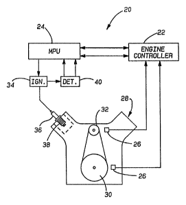
Figure 1 is a schematic illustration showing
the general components of'an ignition and engine
control system embodying the principles of the present
invention;
Figure 2 is a perspective view with portions
broken away showing the ignition transformer of the
present invention positioned on the spark plug of an
internal combustion engine;
Figure 3 is a longitudinal sectional view of
,. a-i
- 14 -
a portion of an ignition transformer embodying the
principles of the present invention;
Figure 4 is a perspective view of the pore,
bobbin, primary.and secondary windings as provided by
the present invention;
Figure 5 is a top plan view of the sore,
bobbin; primary and secondary windings as seen in
Figure 4;
Figure 6 is a perspective view of the
transformer core;
Figure 7 is a longitudinal sectional view of
a second ignition transformer incorporating the
principles of the present invention;
Figures 8(a) and (b) are a graphical
representations of the primary charging current and the
secondary discharge voltage with respect to time;
Figures 9 (a) - (d) are graphical
illustrations of the pressure and temperature at the
spark plug during both a normal combustion event and a
misfire event, as well as the applied voltages and
reflected voltages occurring in the transformer during
both events;
Figures 10(a) - (c) graphically illustrate
the pressure and temperature in the cylinder during a
normal combustion event as well as the applied and
reflected voltages in the ignition transformer during
knock detection;
Figures 11(a) - (c) are graphical
illustrations of the pressure and temperature in the
cylinder during~aut~o-ignition of the en3 gases as tr~ell'
as the applied and reflected voltages in the ignition
transformer;
Figure 12 is a graphical illustration of the
cylinder pressure relative to crank angle position for
various engine loads;
Figure 13 is a graphical illustration of the
breakdown voltage relative to the inductive current
15 -
discharge time; and
Figure 14 is a schematic illustration of the
coil driver circuits, ignition transformer and the
detection circuits utilized in the present invention.
DET~rTLED DESCRIPTION OF THE PREFERRED EMBODIMENT
Referring now to the drawings, an ignition
and engine control system embodying the principles of
the present invention is generally illustrated in
Figur~ 1 and designated at 20. The system includes an
engine controller 22 and an MPU 24 which spends most of
its time executing a main program loop that performs
various engine functions which axe relatively non-
critical from an engine timing standpoint. The rate at
which these functions must be repeated is also
relatively slow in comparison to the engine cycle
itself. This generally means that these "non-critical"
functions can be performed asynchronously from the
engine combustion events.
Fuel injection and ignition events, however,
must be precisely synchronized to the engine cycle. To
accomplish this, the engine controller 22 and MPU 24
are programmed to service interrupts that are triggered
by timing pickups or speed sensors 26 mounted on the
engine 28 r~lative to a flywheel 30 on the crankshaft
and/or a pulley 32 on the camshaft. The interrupts
produced by the timing pickups 26 load a timing element
of the MPU 24 which creates real time control signals
for the fuel injectors and ignition coil drivers at the
correat.instant and for ;the correct duration during the
combustion cycle. The engine controller 22 is also be
coupled to various other engine parameters including
the vehicle ignition signal.
Using the results of the above calculations,
the MPU 24 outputs signals at the proper time through
an ignition or coil driver circuit 34 causing an
ignition coil or transformer 36 to begin charging
directly from the vehicle's 12v power supply. The
~~r~~~~~
- 16
ignition transformer 36, which is mounted directly onto
a spark plug 38 and is known as a coil-on-plug
transformer 36, is charged until its core becomes
saturated. At the appropriate number of engine
degrees before top dead center (HTDC), the MPU 24 then
causes a high speed switching transistor of the coil
driver circuit 34 to open,~ahutting off the current in
the transformer primary. If conditions are right
within the engine cylinder, the secondary capacitance
of the transformer 36 will discharge in a high voltage
current across the spark plug 38 gap and initiate
combustion. After the ignition transformer has been
scheduled to fire, the MPU 24 runs through a series of
programmed algorithms designed to cause mufti-firing of
the spark plug or gerform various engine diagnostic
procedures. If diagnostic procedures are being
performed, the MPU 24 utilizes the detection circuitry
40 as further outlined below.
The ignition transformer 36 of the present
invention is a very low impedance device which, by
design, is capable of generating a significant
secondary voltage (about 25kv) which peaks in
approximately 2-4~s and decays to zero in approximately
100~CS. Since the transformer 36 will fully charge and
saturate its core in about 100~,s from the vehicles 12v
power supply, this means the transformer 36 is capable
of being refired at 200~,s intervals.
Previously, to create signals for
repetitively operating the coil driver circuit 34 or
for nulti-firing an ignition transformer and spark' plug'
at 200~CS intervals, numerous timing interrupts would
have had to been serviced by the engine controller 22
and MPU 24 for each refiring of the spark plug. This,
however, would.result in excessive interrupt loading of
the MPU 24 and would create a significant number of
timing conflicts. With excessive interrupts being
present, the main program the MPU 24 would be disrupted
17 -
at a high frequency during a large percentage of its
execution time resulting in interrupts being nested
within one another. The multiple timing conflicts
would require the MPU 24 to service more than one
interrupt at a time in order to generate the required
control signals. The MPU 24, however, can only execute
one interrupt at a time.
In the present invention, the MPU 24 is
directed by the engine controller 22 to send signals to
the coil driver circuit 34 according to a specific
algorithm programmed into the MPU 24. Thus, the need
~or servicing a multitude of interrupts is eliminated
because of the short time necessary to re-fire the
transformer 36.
' The ignition and engine control system 20 of
the present invention utilizes a specially designed
spark plug mounted ignition coil or transformer 36 as a
feedback element in the engine contral system 20. In
addition to its feedback functions, the ignition
transformer 36 provides an intense, short duration
(less than 100~,s) secondary current that reliably
initiates combustion, even when the spark plug is badly
fouled, and promotes spark plug longevity.
The uniqueness of the ignition transformer 36
provides for a non-intrusive indication of engine
performance by facilitating the measurement of the
spark plug breakdown voltage, a parameter whose
magnitude reflects the relationship between the
combustion pressure. temperature, and fuel
~ , .s, ,
concentration. In general, the relationship between
the pressure, temperature and electrode gap is defined
by Paschen's Law which states:
VBU=R1*Pd+R2* Pd
T T
where P is the pressure; d is the electrode spacings T
ie the temperature; and R1 and R2 are constants.
The voltage level that is generated by the
'~1'~ ~~~.~
- 18 -
ignition transformer 36 is directly related to the
magnitude of the primary winding current, which is a
function of charging time, at the time the ignition
transformer is switched. In the present invention, the
primary current that generates the maximum secondary
voltage is typically reached in a charge time of 100~.s
When the voltage applied to the primary winding is 12v.
A charge time of lass than 100~,s will therefore result
in a secondary voltage that is less than the maximum.
In other words, the shorter the charge tim~, the lower
the secondary voltage of the ignition transformer 36.
Referring now to Figures 2 and 3. the spark
plug mounted or coil-on-plug ignition transformer 36 of
the present invention is generally illustrated therein.
The physical dimensions of the ignition transformer 36
are dictated by the design of the engine 28 itself. To
enable mounting directly on the spark plug 34 itself,
the ignition transformer 36 must be able to fit within
the diameter of a spark plug well 41 of the engine 28.
While this specific design criteria differs ~rom one
engine version to the next, the principles o~ the
present invention will be applicable to the entire
range of spark plug well diameters. The length limit
of the ignition transform is determined by the
clearance between the engine 28 and the hood of the
vehicle (not shown). The length of the ignition
transformer 36 can therefore be adjusted to accoamnodate
the required cross sectional area of its core, as
determined by the various other transformer parameters.
The ignition transformer 36 0'~ the 'presents
invention includes a ferro magnetic core 42 which is
received in a dielectric bobbin 44. Perhaps best seen
in Figures 4-6, the core 42 is substantially
cylindrical and includes portions which define an air
gap 46 that extends the length of the core 42. In
order to provide a very efficient transformer 36, the
retentivity of the core is required to be a very small
_ 1g _
percentage of its maximum flux density, NThen the
magnetizing force (expressed in ampere turns) is
removed from the core 42 of the transformer 36 by
switching off the primary current, the residual
magnetic flux in the core 42 rapidly decreases. The
voltage generated in the secondary winding of the
transformer 36 by the collapse of the primary current
is directly proportional to the number of turns in the
secondary and the magnitude of the change in the core
flux and is inversely proportional to th~ time rate of
change in the core flux. Mathematically stated:
a -Ld6
sec- gt
where esec is the secondary voltage, L is the
inductance of the secondary winding,
_de
Dt is the time rate of change in the care flux, and the
negative sign (-) indicates that the core flux is
decreasing.
To comply with the mathematical performance
requirements, the manufacturing tolerances of the core
42 must be such that the cross sectional area of the
core 42 is substantially constant. While the limit on
the overall length of the transformer 36 and the length
of the transformer core 42 is determined by the
clearance between the engine 28 and the hood of the
vehicle, the dimensional limit on the core's inside
diameter is determined by the access requirements of
the machine which winds the wire of the primary and
secondary windings onto the core 42. The physical ~ '
limits on the outside diameter of the core 42 are
determined by, not only the diameter of the spark plug
well 41, but also the dielectric strength of the
material from which the bobbin 44 is made.
The bobbin 44 which receives the core 42
includes an inner cylindrical sleeve 48 and an outer
cylindrical sleeve 50. Each of the sleeves 48 and 50
'~ ~ e~
further include a radial flange at one end which
extends over the ends of the core 42 to encase it
within the bobbin 44. In the illustrated embodiment,
the inner sleeve.48 is provided with an outwardly
5 directed radial flange 49 at its distal end, while the
outer sleeve 50 is provided with an inwardly directed
radial flange 51 at its proximal end. The outer
diameter of the inner sleeve 48 and the inner diameter
of the outer sleeve 50 are dimensioned sa that the core
10 42 is in surface-to-surface contact with the iruser and
outer sleeves 48 and 50. preferably, the bobbin 44 is
made of a material having a high dielectric strength,
such as one of the well kraown plastics.
Referring now to Figures 3-5, the primary and
15 secondary windings 52 and 54 of the present ignition
trans~oraner 36 can be seer. The windings 52 and 54 are
wound longitudinally about the core 42 and bobbin 44 so
as to extend along the interior surface defined by the
inner sleeve of the bobbin 44, over one of the
20 longitudinal ends of the bobbin 44, along the exterior
surface defined by the outer sleeve 50 and across the
opposing longitudinal end. Facilitating the efficiency
o~ the transformer 36, the primary winding 52 consists
of a lesser number of turns of larger. diameter wire
than the secondary winding 54 and is located on the
bobbin 42 ia~nediately over the air gap 46 defined in
the core 42. The secondary winding 54 of smaller
diam~ter wire substantially covers the remainder of the
core 42 and bobbin 44. The combination of the windings
52 and 54 provides th~ co're 42tand bobbin 44 with a~
generally torodial shape that is best seen in Figure 4.
After the windings 52 and 54 are positioned
over the bobbin 44 and the core 42, the wound assembly
is positioned within a cavity 55 defined within a
cylindrical, insulative housing 56. The inboard or
proximal end of the housing 56, generally designated at
58, is provided with threads 60 engage a similarly
6
- 21 -
threaded adapter 62. The adapter 62 is constructed
from a conductive metal and is configured to allow the
ignition transformer 36 to engage the mounting nut 63
of the spark plug 38.
The proximal end 58 of the housing 56 has
mounted therein, in a threaded engagement, an ignition
terminal 64 which is adapted to electrically engage the
high side terminal 66 of the spark plug 38. To ensure
engagement between the ignition terminal 64 of the
transformer 36 and the high side terminal 66 of the
spark plug 38, the ignition terminal 64 may be provided
with a biased contact element or spring 68 that
positively engages the high side terminal 66 and is
secured by soldering or other bonding techniques within
a seat 70 of tlxe igxaition terminal 64. The biasing of
the contact element 68 not only ensures that electrical
contact will be made with the spark plug terminal 66,
but also provides the transformer 36 with a range over
which it is capable of engaging the spark plug 38.
The transformer 36 is also provided with an
annular seal 72 of rubber or other suitable material in
the housing 56 and is positioned around the high side
terminal 66 and contact element 68. The seal 72
prevents moisture and dirt from entering between the
spark plug 38 and the ignition transformer 36 and
fouling the electrical contact therebetween.
The ignition terminal 64 of the transformer
36 is connected by a lead 74 to the high side 75 of the
secondary winding 64. The low side 77 of the secondary
winding 64 is~conneeted by a second lead 76 to th~
adapter 62 which electrically engages the mounting nut
63 and grounds the spark plug 38. The primary winding
52 has its ends 81 connected to terminals 82, on the
distal end of the transformer 36, which couple the
transformer 36 to the ignition circuitry 34 and the
remainder of the engine control and diagnostic
system 20.
I
,'-.,
- 22 -
Substantially filling the remainder of the
cavity 55 defined by the housing 56 is a suitable
dielectrical material. While numerous other
considerations may dictate the specific nature of the
dielectric filling material, it is believed that
various types of materials could be utilized with
satisfactory~results. For example, the dielectric
filling material may be a preformed solid material
fitted within the housing. Another would include a
setable dielectric material poured into the housing and
allowed to subsequently harden. Still another variety
would include a liquid dielectric material poured into
and sealed within the housing. Additionally, it is
believed that combinations of the above could be used.
As seen in Figure 7, another embodiment of
the transformer 36 of the present invention is
illustrated therein with elements common to the
previaus embodiment being given like designations. In
this second embodiment, the cavity of the transformer
36 is filled with a dielectric liquid and a central
insulative post 83 is positioned to extend into
substantially through the bore of the bobbin 44 from an
end cap 84 which seals the dielectric liquid within the
housing 56.. To further ensure the integrity of the
seal between the end cap 84 and the housing 56, an O-
ring 85 can also be provided at the engagement of the
housing 56 and the adapter 62 for the same purposes.
In substantially all other respects, the transformer 36
of th~ second embodiment is the same as that of the
;.
first.
As an illustrative example of the present
invention, the following is presented for a preferred
embodiment of the ignition transformer 36 when the
diameter restriction on the transformer 36 is 24acmn.
The transformer 36 includes a core 42 made of a
material having the characteristics described above and
which typically experiences a change in flux from about
~1~~'~l~i
- 23 -
14,000 to 500 Gauss. One such material, know as
METGLAS, is produced by the Allied Signal Corporation
and sold as Alloy 2605 TCA. The core 42 has an overall
length of about 3.15 inches, an outer diameter of about
0.67 inches, an inner diameter of about 0.48 and
includes a longitudinal air gap which is about 0.005
inches wide. The bobbin 44 is made from a material
having a dielectric strength of about 680 volts/mil.
One such material is a polyphenylene sulfide
manufactured by the Hoechst Celanese Corporation and
sold under the tradename FORTRON. The inner and outer
sleeves 48 and 50 have a radial thicknesses of about
0.13 inches and 0.11 inches, respectively. Three
turns of #24 wire are provided for the primary winding
52'and 210 turns of #40 wire era provided for the
secondary winding 54. The dielectric liquid is
transformer oil. The resulting transformer 36 exhibits
an inductance of about 12.6~CH (microHenrys) and, when
connected to the vehicle's 12v power source, develops a
maximum primary current of 50A in about 100~.s and
generates a secondary peak volt of about 25kv which
decays to zero in about 100~,s.~
In use. the primary 52 of the ignition
transformer 36 is coupled to the ignition circuit
34. More particularly, the high aide of the primary
winding 52 is connected to a high speed, high current
switching transistor 101 whose function is to switch
the charging current on and off in response to a signal
generated by the MpU 24 (an Tntel 87C51FA 8-bit
microcontroller~in the preferred embodinnent discussed
above) as determined by its programmed algorithm. To
fully charge the transformer 36, the primary winding 52
is connected through the coil driver and ignition
circuit 34 across the vehicle's 12v power supply for
approximately 1,OO~,s. At the end of this time period,
the current within the primary will'have peaked at 50A,
a value at which the transformer core 42 will have
- 24
become saturated. As seen in Figure 8, upon the 50A
current 86 being abruptly shut-off by the high speed
switching transistor 101, a voltage 87 will be induced
in the transformer's secondary 54 which will peak in 2-
4~.s at approximately 25kv and decay to zero in about
100~CS. The low impedance of the ignition transformer
36 results in the voltage being efficiently transferred
to the electrodes 82 of the spark plug 38. Also
because of the transformer's low impedance, the time
necessary to reach a breakdown voltage level that will
cause an arc to form across the electrodes 82 is a
fraction of a microsecond. Under normal engine
operating conditions, the spark plug 38 will conduct in
the range of 7 - l2kv. Tf the primary current in the
transformer 36 is limited by reducing the charging
time, the maximum secondary voltage that is generated
when the primary 52 is turned off will also ba limited.
Referring now to Figure 9, when conditions
exist in the combustion chamber of the engine 28 that
cause the spark plug 38 not to conduct the energy
stored in the capacitance of the secondary 54, the
system 20 of the present invention can be used to
detect this misfiring of the cylinder. During normal
combustion: the MPU 24 causes the coil driver circuit
34 to initiate an increasing coil charging current in
the primary 52 of the transformer 36. Once the
transformer 36 has been fully charged, the current is
switched oft, designated at 88, by the switching
transistors 101 generating a maximum secondary voltage
,~ , , -.
and beginning ignition within the combustion chamber.
If normal combustion has been initiated, the pressure
and temperature at the spark plug electrodes 80 will
generally increase as designated by curves 90 and 92.
To determine whether combustion or misfire
has occurred, the MPU 24 is programmed to cause the
ignition transformer 36 to initiate a charging current
94 and develop a lower, predetermined applied voltage
25 -
at the spark plug gap. This is timed so as to occur
just before top dead center (BTDC). During normal
combustion. the combination of pressure and temperature
at the spark plug electrodes 80 will be sufficient to
permit the lower applied voltage to conduct across the
electrodes 80. As a result, the energy stored in the
secondary capacitance will be discharged across the
electrodes and will not be reflected back into the
primary 54 of the transformer 36. (see Figure 9(c)).
During misfire, however. the pressure and temperature
at the electrode 80 will not have sufficiently
increased, as designated by curves 96 and 98, to enable
the lower applied voltage 94 to conduct. As a result
of this, the energy of the secondary capacitance will
be reflected back into the primary 52 of the
transformer 36 and appear as a negative voltage
excursion 100 which can be detected on the high side of
the switching transistor 101.
AE sears in Figure 14, the detection circuit
40 of the present invention includes a sub-circuit 102
for detecting negative voltage excursions 100. For
each cylinder of the engine 28, the sub-circuit 102
incudes a diode 104 whose cathode is attached to the
one high side of the switching transistor 101. In this
manner, a single detection sub-circuit 102 can be used
to monitor all of the engine's cylinders. For the sake
of clarity, only two of the transistors 101 and diodes
104 are illustrated in Figure 14. The diodes 104 feed
any negative excursion through the sub-circuit 102
whet~ the signal i~s~~conditioned and passed to~ a
negative threshold reference comparator 106. The
comparator 106 outputs a corresponding signal to the
MPU 24 which processes the signal based on its
programmed algorithm and, if necessary, shuts down a
misfiring cylinder.
Detecting auto-ignition of the end gasps
(knock) uses the same basic approach as detecting
- 26 -
misfire. Referring now to Figures 10 and 11, a normal
combustion cycle and a knock combustion cycle are
respectively illustrated therein. During normal
combustion, the .pressure within the cylinder 108, as
indicated by curve 108, does not begin to significantly
increase until ADTC. Thia is also true for the
temperature within the cylinder, as indicated by curve
110. F~owever, during a knock combustion cycle, pockets
of exploding end gas cause pressure waves, which travel
back and forth across the combustion chamber within the
cylinder. along with a dramatic increase in the
cylinder temperature. This typically begins,to occur
around 10° ATDC. The pressure and temperature curves
of the knock combustion cycle are respectively
indicated as curves 112 and 114 in Figure 11, with the
pressure fluctuations being designated at 116 and the
temperature rise being designated at 118.
During the time period when knock is most
likely to occur (typically around 10°-20° ATDC), the
MPU 24 duty cycles the coil driver circuit 34 and
current 120 going to the transformer 36 so as to
produce a series of applied voltages. Because o~ the
combination of pressure 108 and temperature 110 during
normal combustion, the level of the applied voltage 120
is chosen so that the spark plug 38 will not
subsequently conduct during normal combustion. As a
result, a negative voltage excursion 122 is reflected
back into the primary 52. As seen in Figure 10(e), a
negative voltage excursion 122 will be present for each
applied voltage 120~during a normal coribustion cycle.
The sub-circuit 102 feeds this information as an input
to the MPU 24 where it is processed and passed on to
the engine controller 22, which utilizes this
information to.advance the spark timing toward the
threshold of auto-ignition.
In a "knock" combustion cycle (Figure 11),
the applied voltages 120 are again generated when the
'~~~~~~~~1
- 27 -
combination of pressure fluctuations 116 and dramatic
temperature increase 118 are expected to occur. By
applying a series of voltages 120 over this time frame,
the chances that at least one of the applied voltages
120 will correspond with a decreased pressure
fluctuation and allow the applied voltage 120 to
discharge in an arc across the spark plug gap is
increased. As a result, a corresponding negative
voltage excursion 122 will be absent. If one or more
0~ the reflected voltages 122 are missing, designated
at 124, in response to a correspondingly applied
voltage 120, the MPU 24 will sense this through the
detection sub-circuit 102 and send the appropriate
signals to the engine controller 22 so that the spark
timing can be correspondingly stepped toward
eliminating knock. By alternately advancing and
retarding the timing of the engine as described above,
the engine controller 22 is capable of maintaining the
spark timing at the threshold of auto-ignition.
The ignition transformer 36 of the present
invention can also be used to exploit the value of the
breakdown voltage to determine engine load. To
reliably determine the breakdown voltage level, the
relationship between the charging energy (the energy
required to charge the distributed capacitance of the
secondary 54 up to the breakdown voltage level) and the
distributed energy (the energy dissipated by the spark
plug arc current) is used. This relationship is
represented by the equation:
DTs=i/*CVBD2+~*EIp*t
where VBU is the breakdown voltage at the spark plug; C
is the distributive capacitance of the secondary
circuit; E is the arc current voltage at the
electrodes; Ip is the peak arc current at the spark
plug electrodes 80; t is the arc current discharge time
~13~~:~~~
28
which varies inversely with the breakdown voltage; and
DTs is the total energy available to the secondary
circuit. By solving the above equation for the
breakdown voltage, the breakdown voltage can be
expressed as a function of time with the remaining
parameters all being known values dependent on the
specific design of the transformer 36.
Referring now to Figure 12, during the
monitoring of engine load, the spark plug breakdown
voltage is determined at an "interrogat~" time or crank
angle position 126 where the effect of other variables,
such as the temperature, the air/fuel ratio and the
spark advance, are no longer an influence on the
cylinder pressure. This is most likely to occur within
the range of about 20° - 50° ATDC, depending on the
particular engine. The value of the breakdown voltage
at the interrogate crank angle position 126 is
therefore directly proportional to the cylinder
pressure, which in turn is indicative of the engine
load. Three pressure curves, which relate to a heavy
load 128, a light load 130 and an idle load 132, are
shown in Figure 12.
At the "interrogate" crank angle position
126, the coil driver circuit 34 initiates a current 134
(in Figure 9) that charges the primary 52. Specific to
the engine load or pressure then present within the
cylinder, the energy stared in the secondary 54 will
begin discharging at a specific breakdown voltage
across the spark plug gap and will continue discharging
,, ;; .. .
for a corresponding time period.
V~hile direct measurement of the breakdown
voltage is problematic, measuring the duration of the
inductive current discharge, and relating this time to
the breakdown voltage (see Figure 13), is more easily
performed. This is accomplished by a load or second
detection sub-circuit 136 of the detection circuit 40.
Again, a single sub-circuit 136 is used to monitor all
z13~~~~.G
- 29 -
of the engine cylinders.
Once the spark plug 38 has started to conduct
the secondary current, a second set of diodes 138,
whose anodes are attached to the high side of the
switching transistor 101, detect the positive voltage
associated with the secondary current flow and feed the
associated voltage into the load detecting sub-circuit
136 of the detection circuit 40. As long as the arc
current is flowing, the voltage at the high side of the
switching transistor 101 will be significantly above
the l2vdc power supply of the vehicle. The load
detection sub-circuit 136 outputs a pulse to the MPU 24
having a length which corresponds to the duration of
this elevated voltage and the length of time over which
the inductive current discharges. The MPU 24
correlates the inductive pulse width into the breakdown
voltage which, using Paschen's Law, can be correlated
to the pressure in the cylinder and engine load. The
MPU 24 then outputs this information to the engine
controller 22 so that the spark timing, air/fuel ratio
and other ignition and engine control parameters can be
appropriately modified.
More specifically, the inductive pulse width
measurement is started at the end of the ignition dwell
and is done by monitoring the reflection which occurs
in the primary 52 during the secondary discharge. The
reflected signal in the primary 52 and an auto-tracking
reference signal, which compensates for variations in
the power supply voltage, are biased and filtered at
appropriate levels to provid~ an accurate measurement
of the inductive phase. These signals are then fed to
a comparator 140 which detects the inductive current
reducing to zero or near zero. Once the inductive
current has decayed, a signal from the comparator 140
is fed to a flip-flop 142 which has also received an
input indicating the end of the ignition dwell. This
enables the flip-flop 142 to output a signal
~~~~~~~~J
- 30 -
representing the indicting pulse width to the MPU 24.
The MPU 24 then correlates the inductive pulse width to
breakdown voltage allowing the cylinder pressure and
engine load to be determined.
while the above description constitutes the
preferred embodiments of the present invention, it will
be appreciated that the invention is susceptible to
modification, variation and change without departing
from the proper scope and fair meaning of the
accompanying claims.