Language selection

Search

Patent 2134893 Summary

Third-party information liability

Some of the information on this Web page has been provided by external sources. The Government of Canada is not responsible for the accuracy, reliability or currency of the information supplied by external sources. Users wishing to rely upon this information should consult directly with the source of the information. Content provided by external sources is not subject to official languages, privacy and accessibility requirements.

Claims and Abstract availability

Any discrepancies in the text and image of the Claims and Abstract are due to differing posting times. Text of the Claims and Abstract are posted:

  • At the time the application is open to public inspection;
  • At the time of issue of the patent (grant).
(12) Patent: (11) CA 2134893
(54) English Title: METHOD AND COMBUSTOR FOR THE COMBUSTION OF A PREMIXED GAS
(54) French Title: METHODE ET CHAMBRE DE COMBUSTION POUR LA COMBUSTION D'UN PREMELANGE DE GAZ
Status: Expired and beyond the Period of Reversal
Bibliographic Data
(51) International Patent Classification (IPC):
  • F23D 14/02 (2006.01)
  • F23D 14/66 (2006.01)
  • F23L 7/00 (2006.01)
  • F23R 3/10 (2006.01)
  • F23R 3/28 (2006.01)
(72) Inventors :
  • MANDAI, SHIGEMI (Japan)
  • TANAKA, KATSUNORI (Japan)
  • SATO, NOBUO (Japan)
  • TANIMURA, SATOSHI (Japan)
(73) Owners :
  • MITSUBISHI JUKOGYO KABUSHIKI KAISHA
(71) Applicants :
  • MITSUBISHI JUKOGYO KABUSHIKI KAISHA (Japan)
(74) Agent: GOWLING WLG (CANADA) LLP
(74) Associate agent:
(45) Issued: 1999-09-07
(86) PCT Filing Date: 1994-03-08
(87) Open to Public Inspection: 1994-09-15
Examination requested: 1994-11-01
Availability of licence: N/A
Dedicated to the Public: N/A
(25) Language of filing: English

Patent Cooperation Treaty (PCT): Yes
(86) PCT Filing Number: PCT/JP1994/000363
(87) International Publication Number: WO 1994020793
(85) National Entry: 1994-11-01

(30) Application Priority Data:
Application No. Country/Territory Date
72948/1993 (Japan) 1993-03-08

Abstracts

English Abstract


An object of the present invention is to overcome the
disadvantages of a conventional combustor having a fuel-air
premixing nozzle wherein variation in combustion rate
resulting from variation in the fuel concentration of the
premixed gas cause variation in flame length and may
eventually lead to the development of combustive vibration.
This invention provides a combustion method and combustor
which is characterized in that a fluid (8) containing no
fuel is fed between a premixed gas layer (2) formed by
injecting a premixed gas through a premixing nozzle (1) and
a hot gas layer (5) formed from a portion of the hot gas
resulting from the combustion of the premixed gas, the hot
gas layer (5) circulating or staying in a region downstream
of the outlet of the premixing nozzle (1).


Claims

Note: Claims are shown in the official language in which they were submitted.

THE EMBODIMENT OF THE INVENTION IN WHICH AN EXCLUSIVE PROPERTY
OR PRIVILEGE IS CLAIMED ARE DEFINED AS FOLLOWS:
1. A combustor, comprising:
a pilot nozzle arranged in the centre of said combustor and having the
discharge end at a predetermined axial distance for injecting pilot fuel in a
direction
away from the longitudinal axis of said combustor and for generating a first
layer of
hot gas;
an intermediate nozzle arranged around said pilot nozzle and having the
discharge end at same said axial distance for feeding a neutral fluid in said
direction
away from said longitudinal axis and for forming a mid-temperature second
layer
around said first layer; and
a premixing nozzle arranged around said intermediate nozzle and having the
discharge end at same said axial distance for injecting premixed gas in a
direction
parallel to said longitudinal axis and for forming a third layer of premixed
gas around
said second layer, the combustion of said premixed gas being controlled in a
downstream region by the temperature of said second layer.
2. The combustor of claim 1, further comprising a tip at said discharge end of
said pilot nozzle for directing said neutral fluid between said third layer
and said first
layer.
3. A combustion method for burning premixed gas in a combustor, comprising
the steps of:
forming a central layer of hot gas by injecting fuel in a direction away from
the
longitudinal axis of said combustor;
injecting premixed gas in a direction parallel to the longitudinal axis of
said
combustor for forming an exterior layer that is coaxial and about said central
layer;
and
feeding a neutral fluid between said central and said exterior layers in said
direction away from the longitudinal axis of said combustor for forming a
mid-temperature layer between said central and said exterior layers, the
combustion of

said premixed gas being controlled in a downstream region by the temperature
of
said mid-temperature layer.

Description

Note: Descriptions are shown in the official language in which they were submitted.


X134893
DESCRIPTION
Title of the Invention
METHOD AND COMBUSTOR FOR THE COMBUSTION OF A PREMIXED GAS
Technical Field
This invention relates to a method for the combustion
of a premixed gas in a combustor having a fuel-air premix-
ing nozzle and useful for effecting low-NOX combustion and
a combustor therefor. This invention can be applied to
such combustors as gas turbine combustors, boilers, and
furnaces for use in chemical industry.
Background Art
Recently, in order to reduce the NOx content of
exhaust gas from gas turbine combustors and the like, there
is commonly employed a combustion method in which fuel is
premixed with combustion air and the resulting premixed gas
is burned under lean combustion conditions. This method
for the combustion of a premixed gas can eliminate areas
having uneven fuel concentrations and also local areas
burning at higher temperatures, resulting in a marked
reduction in the amount of NOx produced.
FIG. 3 illustrates a part of a burner based on the
conventional method for the combustion of a premixed gas.
In this figure, reference numeral 1 designates a premixing
nozzle, 2 designates a premixed gas, 3 designates a flame
holder, 4 designates a flame, 5 designates a circulating or
- 1 -

2134893
staying hot gas, 6 designates a pilot nozzle, and 7 desig-
nates a pilot fuel.
The premixed gas 2 injected through the premixing
nozzle 1 into the combustion chamber burns so as to go
round the flame holder 3, thus forming downstream a circu-
lating hot gas 5 serving for flame holding.
In this method for the combustion of a premixed gas,
the combustion rate of the premixed gas (i.e., the velocity
at which the flame advances into the unburned mixture)
becomes higher as the temperature of the premixed gas is
elevated and as the fuel concentration of the premixed gas
is increased. In particular, the fuel concentration may
cause marked variation in the resulting combustion rate.
Such variation in combustion rate causes variation in flame
length and may eventually lead to the development of com-
bustive vibration.
Disclosure of the Invention
The present invention has been made for the purpose
of solving the above-described problem and has for its
object the provision of a method and combustor for the
combustion of a premixed gas which can minimize the devel-
opment of combustive vibration due to variation in the fuel
concentration of the premixed gas.
In order to accomplish the above-described object,
the present invention provides:
- 2 -

2 1348 ~ 3
A combustor, comprising: a pilot nozzle; a fuel-air premixing nozzle for
inj ecting a premixed fuel-air gas and forming a premixed fuel-air gas layer
around and
coaxially said pilot nozzle; a passage for feeding a neutral fluid containing
no fuel,
said passage disposed between said pilot nozzle and said fuel-air premixing
nozzle;
and a tip on the discharge end of said pilot nozzle for directing said neutral
fluid
between said premixed fuel-air gas layer and a hot gas layer formed by the
combustion of said premixed fuel-air gas, said hot gas layer circulating or
staying in a
downstream the outlet of said premixing nozzle.
A combustion method for burning premixed gas in a combustor, comprising
the steps of: forming a first layer of hot gas in a central region of said
combustor;
injecting a premixed gas in a second layer that is coaxial and about said
first layer;
and feeding a neutral fluid between said first and second layers, for forming
a third
mid-temperature layer in between said premixed gas and said hot gas.
By the above-described means, a neutral fluid is fed
between the premixed gas layer and the hot gas, so that a
flame is not propagated directly from the hot gas to the
premixed gas. Instead, a mid-temperature gas is generated
by the mixing and diffusion of the hot gas and the neutral
fluid. Thereafter, the premixed gas is burned as a result
of the mixing and diffusion of the mid-temperature gas and
the premixed gas.
The mechanism by which the premixed gas is burned is
such that the hot gas and the premixed gas intermingle with
each other, during this process the premixed gas is heated
- 3 -
Ci..

X134893
by the heat transferred from the hot gas, and combustion is
initiated when the combustion starting temperature is
reached.
Thus, according to the present invention, the pre-
mixed gas is burned under mixing and diffusion rate con-
trol, as contrasted with an ordinary premixed flame in
which combustion is effected by flame propagation. Conse-
quently, it is possible to achieve combustion which is
little affected by the fuel concentration of the premixed
gas. As used herein, "diffusion" means that the hot gas
and the premixed gas intermingle with each other, and "rate
control" means the controlling of the rate of such diffu-
sion. "Diffusion rate control" means the controlling of
the rate at which the hot gas and the premixed gas inter-
mingle with each other.
Moreover, since the hot gas and the neutral fluid are
mixed to generate a mid-temperature gas which is then mixed
with the premixed gas, the flame temperature in this mixing
region is low and the production of NOx in this region is
minimized.
Furthermore, since the premixed gas is burned under
diffusion rate control, the main flame is long, and heat
generation or heat generation quotient can be spread in
space, so that combustive vibration can be prevented. The
reason why combustive vibration can be prevented is that
- 4 -

2134893
the combustion pressure is reduced by dispersion of the
heat generation and, moreover, the variation of flame
length relative to the total flame length becomes smaller
as a result of the prolongation of the flame.
As used herein, "heat generation quotient" means the
per area combustion (dQ/dx) of fuel (Q) with respect to the
axial distance (x) of a combustor.
Hrief Description of the Drawings
FIG. 1 is a schematic diagram illustrating an exem-
plary burner to which the present invention has been ap-
plied;
FIG. 2 is a graphical representation of experimental
data showing the effects of the present invention; and
FIG. 3 is a schematic diagram illustrating a burner
based on the conventional method for the combustion of a
premixed gas.
Best Mode for Carrying Out the Invention
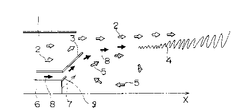
FIG. 1 illustrates an exemplary burner for carrying
out the method of the present invention. In this figure,
the same elements as shown in FIG. 3 are designated by the
same reference numerals and no detailed explanation thereof
is given.
Referring to FIG. 1, a passage for feeding a neutral
fluid 8 is formed between a premixing nozzle 1 and a pilot
nozzle 6. The orifice for injecting the neutral fluid 8
- 5 -

213489 3
into the combustion chamber is configured so as to cause
the neutral fluid 8 to'flow out along the inner wall sur-
face of a flame holder 3 and the outer wall surface of a tip 9 defined at the
discharge
end of the pilot nozzle 6. The neutral fluid 8 is a fluid containing no fuel
and may
comprise, for example, air, exhaust gas, steam or the like.
In the arrangement of FIG. 1, a neutral fluid is fed
between a layer of a premixed gas 2 injected through the
premixing nozzle 1 and a circulating hot gas 5, so that the
premixed gas 2 injected through the premixing nozzle 1 does
not come into direct contact with the hot gas 5. The
neutral fluid 8 is first mixed with the hot gas 5 to gener-
ate a mid-temperature gas. Then, in a downward region,
this mid-temperature gas is mixed with the premixed gas 2
to form a flame 4.
Thus, since the hot gas 5 does not come into direct
contact with the premixed gas 2 fed through the premixing
nozzle 1, it is unlikely that a flame is propagated direct-
ly from the hot gas 5 to the premixed gas 2 and ignites the
premixed gas forcibly before the premixed gas diffuses
sufficiently, as is the case with conventional burners.
That is, the premixed gas 2 separated from the hot gas 5 by
the neutral fluid 8 can be burned under diffusion rate
control, so that a long main flame results. This means
that the heat generation quotient can be spatially spread
and small to prevent combustive vibration.
- 6 -

2134893
FIG. 2 is a graph showing the states of combustive
vibration when combustion was effected in a burner using
air as the neutral fluid 8 according to the method of the
present invention and in a conventional burner. In this
graph, the ordinate shows the internal pressure fluctuation
of the combustor which serves as a measure of combustive
vibration, and the abscissa shows the proportion of the
pilot fuel (i.e., the pilot fuel 7 for the formation of a
diffusion flame) to the total fuel (i.e., the main fuel
plus the pilot fuel). FIG. 2 indicates that, regardless of
the proportion of the pilot fuel, the internal pressure
fluctuation ratio is lower in the presence of a neutral
fluid (the present invention) than in the absence of a
neutral fluid (the~prior art). That is, FIG. 2 indicates
less combustive vibration in the presence of a neutral
fluid, demonstrating the effects of the present invention.
The present invention is not limited to the burner
design illustrated in FIG. 1, but comprehends all
combustors involving the formation of a circulating flow
wherein a neutral fluid is fed between the circulating flow
and the premixed gas. For example, the present invention
can be applied to combustors having various flame-holding
plates and combustors forming a circulating flow or a
stagnation point in a region having an abruptly expanded
flow path.

Representative Drawing
A single figure which represents the drawing illustrating the invention.
Administrative Status

2024-08-01:As part of the Next Generation Patents (NGP) transition, the Canadian Patents Database (CPD) now contains a more detailed Event History, which replicates the Event Log of our new back-office solution.

Please note that "Inactive:" events refers to events no longer in use in our new back-office solution.

For a clearer understanding of the status of the application/patent presented on this page, the site Disclaimer , as well as the definitions for Patent , Event History , Maintenance Fee  and Payment History  should be consulted.

Event History

Description Date
Inactive: IPC from MCD 2006-03-11
Time Limit for Reversal Expired 2004-03-08
Letter Sent 2003-03-10
Grant by Issuance 1999-09-07
Inactive: Cover page published 1999-09-06
Inactive: Final fee received 1999-06-02
Pre-grant 1999-06-02
Notice of Allowance is Issued 1999-03-22
Letter Sent 1999-03-22
Notice of Allowance is Issued 1999-03-22
Inactive: Status info is complete as of Log entry date 1999-03-16
Inactive: Application prosecuted on TS as of Log entry date 1999-03-16
Inactive: Approved for allowance (AFA) 1999-02-19
All Requirements for Examination Determined Compliant 1994-11-01
Request for Examination Requirements Determined Compliant 1994-11-01
Application Published (Open to Public Inspection) 1994-09-15

Abandonment History

There is no abandonment history.

Maintenance Fee

The last payment was received on 1999-02-03

Note : If the full payment has not been received on or before the date indicated, a further fee may be required which may be one of the following

  • the reinstatement fee;
  • the late payment fee; or
  • additional fee to reverse deemed expiry.

Please refer to the CIPO Patent Fees web page to see all current fee amounts.

Fee History

Fee Type Anniversary Year Due Date Paid Date
MF (application, 4th anniv.) - standard 04 1998-03-09 1998-01-27
MF (application, 5th anniv.) - standard 05 1999-03-08 1999-02-03
Final fee - standard 1999-06-02
MF (patent, 6th anniv.) - standard 2000-03-08 2000-02-07
MF (patent, 7th anniv.) - standard 2001-03-08 2001-02-19
MF (patent, 8th anniv.) - standard 2002-03-08 2002-02-18
Owners on Record

Note: Records showing the ownership history in alphabetical order.

Current Owners on Record
MITSUBISHI JUKOGYO KABUSHIKI KAISHA
Past Owners on Record
KATSUNORI TANAKA
NOBUO SATO
SATOSHI TANIMURA
SHIGEMI MANDAI
Past Owners that do not appear in the "Owners on Record" listing will appear in other documentation within the application.
Documents

To view selected files, please enter reCAPTCHA code :


To view images, click a link in the Document Description column. To download the documents, select one or more checkboxes in the first column and then click the "Download Selected in PDF format (Zip Archive)" or the "Download Selected as Single PDF" button.

List of published and non-published patent-specific documents on the CPD .

If you have any difficulty accessing content, you can call the Client Service Centre at 1-866-997-1936 or send them an e-mail at CIPO Client Service Centre.


Document
Description 
Date
(yyyy-mm-dd) 
Number of pages   Size of Image (KB) 
Abstract 1995-10-28 1 22
Claims 1995-10-28 1 22
Cover Page 1995-10-28 1 20
Drawings 1995-10-28 3 42
Description 1995-10-28 7 227
Cover Page 1999-09-01 1 37
Description 1999-02-03 7 261
Claims 1999-02-03 2 49
Drawings 1999-02-03 3 28
Representative drawing 1999-05-17 1 6
Representative drawing 1999-09-01 1 6
Commissioner's Notice - Application Found Allowable 1999-03-22 1 164
Maintenance Fee Notice 2003-04-07 1 174
Correspondence 1999-06-02 1 29
Fees 2000-02-07 1 29
Fees 1998-01-27 1 28
Fees 1999-02-03 1 33
Fees 1997-02-04 1 31
Fees 1995-12-28 1 29
Prosecution correspondence 1994-11-01 11 272
International preliminary examination report 1994-11-01 14 432
PCT Correspondence 1995-02-15 2 62
Prosecution correspondence 1998-12-02 2 64
Prosecution correspondence 1998-10-09 2 78
Prosecution correspondence 1998-03-06 3 122
Examiner Requisition 1998-04-09 2 47
Examiner Requisition 1997-09-16 2 46
Prosecution correspondence 1997-08-27 1 33
Examiner Requisition 1997-05-23 1 62
Prosecution correspondence 1997-05-07 2 90
Prosecution correspondence 1997-05-07 2 96
Examiner Requisition 1996-11-26 2 61
National entry request 1994-11-01 6 265