Note: Descriptions are shown in the official language in which they were submitted.
2 1 34~8q
HUMIDIFIER AND METHOD FOR HUMIDIFYING AIR
BACKGROUND OF THE INVENTION
The present invention relates generally to
humidifiers and methods for humidifying industrial
buildings, and more particularly, to those used to humidify
paint booths.
Conventional industrial air humidifiers for large
buildings and paint booth~ often employ corrugated
cardboard or glass fibers, joined by resins, as absorptive
pads for storing water to be evaporated into a stream of
air. These absorptive pads often are arranged in
rectangular panels many feet high and several feet thick.
Overhead pipes carry water which cascades down over and is
absorbed by the absorptive pads. An air stream is then
forced through the absorptive pads with the air stream
picking up moisture to increase the humidity of the air
stream.
Industrial humidifiers which utilize the above
described absorptive pads have a number of problems.
First, to ensure the absorptive pads are
sufficiently saturated, a great deal of water must be
supplied to the absorptive pads. Consequently, a large
71 1~1
2134983
amount of water also drains from the absorptive pads into
collection trays located beneath the absorptive pads. The
waste water is often treated for recirculation. This
additional waste water burdens a facility's waste water
treatment equipment and adds to the cost of operating the
facility.
Second, in order for the absorptive pads to hold
sufficient quantities of water to achieve the necessary
humidification, the absorptive pads are often several feet
thick. A large pressure head is needed to force the air
stream through the absorptive pad. This, in turn, requires
a larger fan or blower motor to develop a sufficient
pressure head. Also, the large size of the absorptive pad
increases the overall size of the humidifier.
Third, when the humidifier is shut down, the flow
of water to the absorptive pad typically is stopped. This
leads to the absorptive pad eventually drying out. A
significant amount of time is necessary to then resaturate
the absorptive pad during start up from a dried initial
state.
Fourth, because of the massive size of the
absorptive pad and the large amount of water stored
therein, it is difficult to quickly and precisely adjust
the humidity of the air stream exiting the humidifier to a
desired level. This lack of precision can be particularly
detrimental in paint booths where tight tolerances on
humidity levels are critical to the proper adherence of
paint to parts. Accordingly, there is a need for an
industrial humidifier which can quickly and precisely
adjust the humidity of an air stream.
71 141
2134~89
Finally, the absorptive pads accumulate scale from
the cascading water. When the pads become sufficiently
encumbered with scale, the pads have to be replaced.
Otherwise, particles of scale may break loose and
contaminate the humidified air stream.
The present invention seeks to overcome the
above-identified problems associated with conventional
industrial humidifiers for buildings and paint booths which
utilize large absorptive pads.
SUMMARY OF THE INVENTION
The present invention relates to a humidifier for
controlling the humidity of a stream of air and a method
for humidifying a stream of air. A first embodiment of the
humidifier comprises a housing having an upstream inlet for
receiving a stream of air to be humidified and a downstream
outlet for expelling the stream of air after it has been
humidified. Also, it has a spray apparatus in the housing
for spraying a mist of water droplets into a stream of air.
A mist eliminator, located in the housing, intercepts the
mist of water droplets. The mist eliminator is comprised
of elongated monofilaments interlaced and sufficiently
spaced from each other such that the air stream moves
freely therethrough but sufficiently close to each other so
that the mist of droplets is captured in a liquid phase by
the mist eliminator and substantially completely converted
by flow along the monofilaments into a vapor or gaseous
phase in the form of increased humidity in the stream of
air.
71 141
2134389
A humidity sensor, located downstream of the mist
eliminator, senses the relative humidity of the stream of
humidified air. A controller controls the quantity of
water sprayed into the stream of air in response to the
humidity sensed to maintain a predetermined level of
humidity in the stream of air expelled from the downstream
outlet.
Ideally, there are a plurality of planar layers of
mesh pads forming the mist eliminator including an upstream
mesh pad and a downstream mesh pad, each layer being
oriented generally perpendicular to the flow of the stream
of air. The upstream layer may be made of a coarser mesh
of monofilaments than the downstream layer whereby the
upstream layer intercepts larger droplets and the
downstream layer intercepts smaller droplets passing
through the upstream layer. Preferably, the monofilaments
are made of a non-absorbent, non-flammable material such as
polypropylene or other plastics.
The spray apparatus preferably includes a plurality
of spaced apart nozzles and a plurality of valves with
actuators, the actuators being selectively governed by the
controller to regulate the quantity of water sprayed from
the nozzles. Each nozzle may spray a discrete portion of
the mist eliminator wherein when all nozzles are spraying
water, essentially all of the mist eliminator is covered
with a mist of water droplets.
A heater is preferably provided with the amount of
heat expelled from the heater being variably controlled by
the controller. Further, a rinsing mechanism may be
71 141
2134~89
included to periodically wash scale off of the mist
eliminator.
A second embodiment of the humidifier is also
disclosed which includes a housing having an upstream inlet
for receiving a stream of air to be humidified and a
downstream outlet for expelling the stream of air after it
has been humidified. A fan is in air flow communication
with the housing. The fan generates a stream of air
passing through the housing. A heater, also located in the
housing, has a source of heat providing a region of intense
heat for heating the stream of air. ~ater is supplied by a
water supply which directs water into the region of intense
heat so that the water is instantaneously evaporated or
flashed into the stream of air. Humidity and temperature
sensors are located downstream of the mist eliminator for
sensing the humidity and temperature levels of the expelled
airstream. These sensors communicate with the controller
so that the controller may govern the amount of water
supplied and control the amount of heat necessary to
maintain the setpoint levels of humidity and temperature.
This is accomplished by actuation or modulation of the
water and gas valves which are in communication with the
controller.
Preferably, a mist eliminator, located downstream
of the heater, removes any droplets of water suspended in
the air stream so that droplets of water are not expelled
from the downstream outlet. Ideally, the heater is a
burner which burns a combustible gas and generates a flame
defining the region of intense heat. Further, the water
supply includes a nozzle which directs water into the flame
to evaporate the water. Further, the humidifier may
71 141
213~383
include first and second temperature sensors located
upstream and downstream of the heater. The temperature
sensors communicate with the controller so that the
controller may control the amount of heat transferred to
the stream of air thereby controlling the temperature of
the expelled stream of air.
A third embodiment constructed in accordance with
the present invention has an upstream inlet that receives a
stream of air, means for humidifying the stream of air, and
a downstream outlet for expelling the humidified air. A
heater is positioned to direct a flame substantially
vertically downward. Pressurized water and pressurized air
are supplied into the flame, causing the water to be
virtually instantaneously flashed into the stream of air.
The humidifier is constructed such that the airstream
enters the inlet and proceeds downwardly past the heater.
Just below the region where water is flashed into the
airstream, the humidifier housing forces the airstream to
make a right angle turn and proceed horizontally through a
mist eliminator. Downstream humidity and temperature
sensors are used to monitor the humidity and temperature of
the expelled airstream. These sensors communicate with a
controller that governs the amount of water supplied and
the temperature of the heat source. The controller
operates by selectively actuating water and gas valves.
The third embodiment, like the first and second
embodiments, may be used to humidify air while preventing
water droplets from escaping from the system. This is
important because such droplets could have a detrimental
effect in controlled environments such as paint booths.
71141
2134989
A first method is taught for humidifying a stream
of air which includes the following steps. A stream of air
is passed downstream through a housing. Droplets of water
are sprayed into the stream of air and are intercepted and
coalesced on a mist eliminator. The mist eliminator
preferably has interlaced elongated filaments which
intercept and coalesce water droplets sufficiently to
eliminate the water droplets from the stream of air. The
droplets are passed along the filaments in a manner to
continually renew the surfaces of the droplets so that the
droplets evaporate into the stream of air. Next, the
humidity of the stream of air is sensed downstream from the
mist eliminator. The quantity of water sprayed on the mist
eliminator is then adjusted to maintain a predetermined
level of humidity downstream from the mist eliminator.
The method may further include heating the stream
of air upstream from the mist eliminator thereby
controlling the temperature of the stream of air. Also,
the mist eliminator may be rinsed with an acidic solution
to remove scale from the mist eliminator.
A second embodiment of a method for humidifying air
is also disclosed. The method includes providing a region
of intense heat for heating a stream of air passing
thereby. A quantity of water is supplied to the region of
intense heat so that the water is substantially and
instantaneously evaporated into the stream of air
increasing the amount of water vapor in the stream of air,
thus raising the relative humidity. The humidity and
temperature of the stream of air downstream of the region
of intense heat are sensed. Based upon the sensed humidity
and temperature, the quantity of water provided to the
71141
213~389
region of intense heat is adjusted as is the amount of heat
transferred by the region of intense heat to maintain a
predetermined level of humidity and temperature in the
humidified stream of air. Preferably, the region of
intense heat is provided by using a burner burning a
combustible gas to produce a flame defining the region of
intense heat.
Ideally, the quantity of water is provided by
spraying droplets of water from at least one nozzle into
the flame to generally instantaneously evaporate the water.
Also, a mist eliminator may be provided downstream of the
region of intense heat to substantially eliminate any
droplets of water not evaporated from the stream of air.
Therefore, the expelled stream of humidified air is
generally free of droplets of water.
In a third method of operation, pressurized air is
injected with water into a region of intense heat. The
pressurized air assists in the evaporation process.
An object of the present invention is to provide a
humidifier which uses a mist eliminator of interlaced
elongated filaments to collect a spray of water droplets
which are then evaporated into a stream of air.
A further object is to provide a humidifier which
utilizes water directed to a region of intense heat to
substantially completely and instantaneously evaporate the
water into a stream of air.
An additional object is to use a mist eliminator to
remove air droplets from a stream of humidified air so that
71141
213~389
the water droplets cannot adversely affect an environment
such as a paint booth.
It is yet another object to provide an industrial
humidifier which uses an evaporative pad that does not
absorb water and which can rapidly and accurately supply a
large quantity of air humidified to within +1% relative
humidity over a wide range of relative humidities and can
do so in just a few minutes with little or no start-up time
involved.
It is a further object to provide a humidifier
which produces relatively little waste water as compared to
conventional industrial humidifiers having a similar output
capacity.
Another object is to provide a humidifier which
produces only a relatively small static pressure loss in an
air stream passing therethrough thereby requiring only a
relatively small fan or blower motor to generate the air
stream.
It is still yet another object to provide a
humidifier which is more compact than conventional
industrial humidifiers of similar output capacity.
An additional object is to provide a humidifier
having a washing mechanism for removing scale from an
evaporative pad so that scale build-up is minimized thereby
extending the working life of the evaporative pad.
Another object of the invention is to add energy to
water injected into a region of intense heat to enhance the
71141
213~389
evaporation of the water. In a preferred embodiment of the
invention, pressurized air is employed to add energy to the
injected water.
Other prior art humidifiers of comparable size to
the present invention use large quantities of water, which
must be purchased and subsequently cleaned. Virtually no
water is wasted in the present invention, thereby reducing
the cost of operating by reducing the amount of water
purchased and the cost of cleaning the water used.
Furthermore, since no water is wasted, it is unnecessary to
add biocides to the water to prevent biological growth
incident with moisture.
Other objects of the present invention will become
apparent from the following description and drawings which
illustrate preferred embodiments of the present invention.
BRIEF DESCRIPTION OF THE DRAWINGS
FIGURE 1 is a perspective view, partially in
cutaway, of a humidifier made in accordance with a first
embodiment of the present invention;
FIGURE 2 is an elevational view of a spray
apparatus used in the humidifier of FIG. l;
FIGURE 3 is a fragmentary cutaway view of a nozzle
of the spray apparatus spraying water onto a mist
eliminator with unevaporated water draining into a
collection tray;
71141
2131989
FIGURE 4 is a fragmentary schematic view of water
droplets passing through first and second layers of mesh
pads with water coalescing upon and evaporating from the
mesh pads;
FIGURE 5A is a fragmentary perspective view of a
layer of a mesh pad from FIG. 4;
FIGURE 5B is a sectional view taken along line
5B-5B of FIG. 5A;
FIGURE 6 is a schematic view of active components
of the humidifier communicating with a controller;
FIGURE 7 is a perspective view, partially in
cutaway, of a second embodiment of the present invention;
FIGURE 8 is a schematic view illustrating the
operation of the humidifier of FIG. 7;
FIGURE 9 is a front elevational view of a burner
being surrounded by a plurality of water nozzles;
FIGURE 10 is a top view of a humidifier system
constructed in accordance with another preferred embodiment
of the present invention;
FIGURE 11 is a rear view of the humidifier system
of FIG. 10;
FIGURE 12 is a cross sectional view of the
humidifier system of FIG. 10, taken along the line 12-12;
71141
12 213~989
FIGURE 13 is a perspective view, partially in
cutaway, of the humidifier system of FIG. 10;
FIGURE 14 is an enlarged cross sectional view of
the heater shown in FIG. 13, taken along the line 14-14;
and
FIGURE 15 is a schematic view illustrating the
heater shown in FIGS. 12 through 14 along with means for
supplying water and pressurized air to the heater.
DETAILED DESCRIPTION OF PREFERRED EMBODIMENTS
Turning now to the drawings, where like reference
numerals indicate like elements, there is shown in FIG. 1 a
humidifier 10 constructed in accordance with a first
embodiment of the invention. The humidifier is arranged to
heat and humidify a stream of air passing longitudinally
downstream therethrough. A pair of arrows indicate the
direction of air flow. Humidifier 10 includes a housing 12
supporting a heater 14, and a spray apparatus 16 which
sprays water droplets upon a mist eliminator 20. An access
door 21 in housing 12, shown in phantom lines, provides
access to mist eliminator 20 and spray apparatus 16. A
flexible duct 22 connects an outlet 24 in housing 12 with a
blower or fan 26. Housing 12 has inlet 28 at its upstream
end with a damper 30 therein for closing off inlet 28 and
partially regulating the air flow through humidifier 10.
Housing 12 is made up of a plurality of metal sheets
appropriately joined together to form a longitudinally
extending rectangular conduit. Steel struts 31 provide a
framework supporting the metal sheets. A control box 43,
71 1 41
213 i389
enclosing a controller 42, is attached to the outside of
housing 12.
Preferably heater 14 is a burner which burns a
combustible gas and is available from Eclipse Combustion of
Rockford, Illinois, Model No. AH.
Also located within housing 12 are a pair of
temperature sensors 32 and 34 and a pair of humidity
sensors 36 and 38. Sensors 32 and 36 are located between
heater 14 and mist eliminator 20. Sensors 34 and 38 are
located downstream of mist eliminator 20. For purposes of
this application, humidity sensors 36 and 38 are sensors
that generally are responsive to the amount of water vapor
present in the stream of air. Sensors 36 and 38 may
measure relative humidity, dew point or the like. However,
p~eferably, the quantity evaluated is relative humidity.
While shown separately, in this preferred embodiment, the
upstream and downstream temperature and relative humidity
sensors are actually combined in single humidistat units.
Controller 42, as shown in FIG. 6, controls the
operation of humidifier 10. In particular, controller 42
receives input from sensors 32, 34, 36 and 38 and outputs
signals to heater 14, damper 30, spray apparatus 16, and
blower 26 to control the humidity and temperature of air
exiting humidifier 10. Further, controller 42 also
controls a plurality of solenoid actuated valves as
described below.
Spray apparatus 16, as best seen in FIGS. 1 and 2,
includes first, second and third conduits 44, 46 and 48
which carry water and are in fluid communication with
71l4~
2131~83
14
respective spray nozzles 52, 54 and 56. A connecting
conduit 50 fluidly joins conduits 44, 46 and 48 to a
pressurized water supply 53 by way of a valve 51.
First conduit 44 is C-shaped with nozzles 52
located at corners of the rectangular configuration.
Second conduit 46 is diamond shaped with nozzles 54 being
disposed at each of its corners. Finally, third conduit 48
carries a single nozzle 56 which is situated in the center
of first and second conduits 44 and 46. When all of
nozzles 52, 54 and 56 are active, they provide a spray
pattern which generally covers all of mist eliminator 20.
It will be appreciated that dirferent configurations of
nozzle layouts are possible which still insure that most of
mist eliminator 20 is covered by sprays of water droplets.
Also, different types of nozzles can be employed to produce
water droplets having different maximum sizes.
First, second and third conduits 44, 46 and 48 are
connected to water supply 53 through respective actuators
60, 62 and 64, each of which has an electrically controlled
solenoid valve for varying the amount of water supplied to
respective conduits 44, 46 and 48. Controller 42
individually controls the actuators 60, 62 and 64 of spray
apparatus 16 thereby regulating the quantity of water
expelled by nozzles 52, 54 and 56. Any one, two or three
of actuators 60, 62 and 64 may be activated to provide the
appropriate amount of water to achieve a desired relative
humidity level downstream of mist eliminator 20.
Nozzles 52, 54 and 56 are available from Bete Fog
Nozzle, Inc. of Greenfield, Massachusetts, Model PJ15,
stainless steel.
71141
15 21 34q89
Spray apparatus 16 also has a washing apparatus 66
for removing scale from mist eliminator 20. Washing
apparatus 66 includes a tank 67 for storing an acid
solution (such as a mild sulfuric acid-solution H2SO~) and
a solenoid operated valve 68 which is in fluid
communication with connecting conduit 50 and nozzles 52, 54
and 56. Water from water supply 53 is shut off using valve
51 when valve 68 is opened to allow the acid solution to
spray on mist eliminator 20. This acidic spray rinses
scale off of mist eliminator 20. Valves 51 and 68 are also
controlled by controller 42.
Mist eliminator 20 is comprised of a plurality of
layers of interconnected mesh pads 76 and 78 mounted on a
rectangular frame 71. A plurality of horizontal and
ertical support bars 72, as seen in FIG. 1, are attached
to rectangular frame 71. Plastic ties (not shown) are used
to secure mesh pads 76 and 78 to support bars 72. Frame 71
is slidably inserted and mountable within housing 12 and is
easily removable. Support bars 72 are preferably stainless
steel, however, they may also include fiber-reinforced
plastic, aluminum or a variety of materials providing high
strength and low weight.
Turning now to FIGS. ~, 5A and 5B, FIG. 4
schematically shows a portion of the pair of generally
planar, longitudinally spaced mesh pads 76 and 78 which are
oriented perpendicular to the flow of the stream of air.
Preferably, mesh pads 76 and 78 are constructed in
accordance with U.S. Patent No. 4,022,596 (Pedersen).
Mesh pads 76 and 78 are manufactured hy and are
71 1~1
A
213~89
16
available from Kimre Incorporated of Perrine, Florida. In
particular, model B-Gon Mist Eliminator Pads are used.
FIG. 5A illustrates that mesh pads 76 and 78 are
comprised of interlaced filaments 70 forming a matrix of
pyramid-like squares 80. Parallel rows of filaments 70 run
orthogonally to other parallel rows of filaments 70, as
indicated in FIG. 5B. This particular construction of
interwoven filaments 70 provides a high void fraction which
allows a stream of air to easily pass therethrough while
also providing a high removal efficiency of the sprayed
water droplets. Removal efficiency is the fraction of
liquid droplets passing through the mesh pad which are
captured. Void fraction is the volume of free space in a
pad relative to the overall volume of space the pad
occupies.
While meshes as described are preferred, other
meshes having interlaced or interconnected filaments or the
like, which also efficiently remove water drops without
creating a significant pressure head loss, are also within
the scope of this invention. Filaments 70 are preferably
manufactured from plastic, and most preferably from
polypropylene. Other materials, ideally non-flammable, may
also be used to form mesh pads 76 and 78.
As shown schematically in FIG. 4, mist eliminator
20 includes two or more layers of pads aligned generally
perpendicular to the flow of the air stream through
humidifier 10. The upstream mesh pad 76 is made of a
coarser mesh of filaments 70 than is downstream layer 78.
Further, filaments 70 of upstream mesh pad 76 are
preferably larger in diameter than those of downstream mesh
71141
17 21 3~89
pad 78. While only two layers of mesh pads 76 and 78 are
shown for exemplary purposes in FIG. 4, ideally, four or
five layers of these planar mesh pads will actually be used
in this first embodiment. The coarseness of the meshes and
void fractions of the mesh pads will decrease from the
upstream to the downstream direction.
Depending on the use of humidifier 10, more and
finer layers of mesh pad may be used to increase the
removal efficiency of the mist eliminator 20. For example,
with vehicle paint booths, very high removal efficiencies
are desirable. For only general humidification purposes,
mist eliminators may have a much lower removal efficiency.
The following is a predicted mechanism for the
humidification process. Water droplets from one or more of
nozzles 50, 52 or 54 are sprayed upon mist eliminator 20.
Larger water droplets are intercepted by upstream layer 76
and coalesce along filaments 70. Smaller water droplets
pass through the coarser upstream layer 76 and are
intercepted and removed by downstream layer 78. Due to
gravity, the coalesced water droplets move downwardly along
vertically extending filaments 70. Also, due to adherence,
the coalesced water droplets also travel along horizontally
extending filaments 70.
As the water droplets move along the filaments 70
and encounter intersections of filaments 70, the outer
surface of the water droplets are constantly undergoing
surface renewal. That is, the water droplets are churned
with the interior portions of the water droplets being
transferred to the outer surfaces of the droplets, and
water molecules located on the water droplets exterior
71141
2139~83
18
surfaces being transferred inwardly. Therefore, virtually
all portions of the water droplets are exposed to the warm
stream of air passing through mist eliminator 20. This
constant surface renewal enhances the evaporation of the
water droplets increasing the humidity of the stream of
air.
As the stream of air carrying the water droplets
flows over each individual filament 70, mist eliminator 20
forms rotating eddies in the air stream behind or in the
direction away from the movement of the air stream being
treated in relation to filaments 70. These eddies,
therefore, move in the direction of the bulk flow of the
stream of air being treated and are, in turn, encountered
by subsequent perpendicularly positioned filaments 70.
Because of this and because of the substantial increase in
the number and length of the individual filaments 70 which
provide this effect, the stream of air is constantly
subjected to this kind of rotating contact. This contact
has the effect of increasing the exposure of the stream of
air for evaporation and removal of liquid-state water
droplets.
Ideally, all of the water droplets are evaporated
into the stream of air to achieve a desired humidity level
in the stream of air exiting humidifier 10. However, as a
practical matter, not all the water droplets are
evaporated. Some droplets fall downwardly into a
collection tray 82. Tray 82 connects to an outlet drain 86
which, in turn, is connected with either a storage tank or
a water treatment system (neither of which is shown) or
drained to waste.
71~41
2131~9
19
Preferably, all the water droplets passing through
mist eliminator 20 are intercepted by mesh pads 76 and 78.
If water droplets are allowed to escape from humidifier 10,
these water droplets may have a detrimental effect in
environments such as paint booths where the water droplets
can cause an adherence problem between paint and parts to
be painted.
Consequently, mist eliminator 20 is designed to
remove a high percentage of the water droplets sprayed from
spray apparatus 16. Utilizing finer meshes and smaller
diameters of filaments, along with using a greater number
of layers of pads in mist eliminator 20, the percentage of
the water droplets removed can be increased. However, a
greater pressure head will then be needed to move the
stream of air through mist eliminator 20. Also, the faster
the stream of air passing through mist eliminator 20, the
lower the removal efficiency. Therefore, the velocity of
air flow through humidifier 10 should be limited to
acceptable levels so that adequate removal of water
droplets occurs. Preferably, the air flow velocity will be
limited to less than 500 feet per minute.
In operation, a predetermined amount of air is
drawn into humidifier 10 by adjusting damper 30 and the
speed of blower 26. The air stream passes by and is heated
by heater 14. This heating dries the air to a
predetermined temperature and humidity which is checked by
upstream temperature and humidity sensors 32 and 36.
Signals are then relayed from sensor 32 and 36 to
controller 42. The temperature and humidity are also
checked downstream by temperature and humidity sensors 34
71 141
213~89
and 38 with those signals also being input to
controller 42.
One, two, or all three of actuators 60, 62 or 64
are selectively opened resulting in water droplets being
sprayed upon mist eliminator 20. Heater 14 and the water
flow from spray apparatus 16 are adjusted in response to
the sensed parameters of sensors 32, 34, 36 and 38 to
quickly and accurately achieve predetermined humidity and
temperature levels in the expelled stream of air.
When a predetermined amount of scale on mist
eliminator 20 has accumulated, blower 26 and valve 51 are
shut off and valve 68 is opened. A supply of the mild
acidic solution is released through valve 68, actuators 60,
62 and 64, and nozzles 52, 54 and 56. The acidic solution
is collected by mist eliminator 20 thereby placing the
scale in solution. The scale laden acidic solution then
drains into collection tray 82. Consequently, mist
eliminator 20 need be replaced less frequently than in an
apparatus not having this scale-removing feature. If
excessive scale is allowed to build up, the scale may break
free from mist eliminator 20 and contaminate the stream of
alr .
Based upon varied sensed levels of temperature and
humidity, the output of spray apparatus 16 is adjusted to
achieve a desired temperature and humidity output from
humidifier 10. Likewise, varying the thickness and types
of pads forming mist eliminator 20 can be used to optimize
pressure head drop and removal efficiency. Because water
droplets adhere to mist eliminator 20 rather than being
absorbed as with conventional absorptive pads, output
71141
21~89
21
humidity levels can be rapidly and accurately adjusted to
precise levels, preferably in the range of +1% relative
humidity. Using humidifier 10, virtually all of the
sprayed water is evaporated. Therefore, relatively little
water is drained into collection tray 82. This minimizes
the amount of water which must subsequently be treated by a
waste water treatment plant. Further, humidifier 10 is
ready to operate immediately without a need to saturate a
large absorbent pad as in conventional humidifiers.
A second embodiment constructed in accordance with
the present invention is shown in FIG. 7. Humidifier 100
includes a housing 102 connected to an inlet conduit 104
which has an inlet 106 for receiving a stream of air. The
downstream end of housing 102 has an outlet 110. Flexible
conduit 112 connects outlet 110 with a fan or blower 114.
Blower 114 has a screen 116 located in a rectangular outlet
120. Housing 102 is again made up of metal sheets 108
attached to steel struts 109. A door 105 provides access
to the interior of housing 102. A control box 111 is
attached to housing 102.
To heat the stream of air passing through
humidifier 100, a heater 122 is provided in the upstream
end of housing 102. Heater 122 projects a flame 124 to
heat the passing stream of air. It will be appreciated
that any comparable heater which provides an intense region
of heat which can receive water and which can relatively
instantaneously evaporate or flash the water from a liquid
to a gaseous state, can be used in place of heater 122.
The amount of heat provided by heater 122 to the stream of
air is controlled by a controller 148, located within
control box 111, through the operation of a gas valve 154.
71~41
213~3~9
22
Located upstream of heater 122 is a damper 126 which again
controls the size of the opening into the upstream end of
housing 102.
A water supply 130 provides water to heater 122. A
reservoir 132 maintains a reserve of water. A float and
valve assembly 133 ensures that reservoir 132 has a ready
supply of water to be pumped to heater 122. Conduit 134
carries water from reservoir 132 to heater 122. A pump 136
is used to pressurize the water in conduit 134. In the
preferred embodiment, this pressure is maintained at a
constant pressure of approximately 200 psi. Located at the
distal end of conduit 134 are a plurality of spray nozzles
140 and 142. Spray nozzles 140 and 142 are arranged to
direct their spray of water into the centerline of flame
124. As the spray from spray nozzles 140 and 142 meets
flame 124, the water is substantially instantaneously
evaporated or flashed from a liquid phase into a vapor
phase thereby adding water vapor to the stream of air.
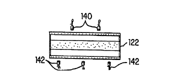
Nozzles 140 and 142, as shown in FIG. 9, are
preferably spaced six inches on center along the transverse
length of heater 122. For example, with a twenty foot long
heater, 40 nozzles 140 and 142 would be used. Also, as
shown, nozzles 140 and 142 are arranged alternatively above
and below heater 122. The nozzles are ideally operated to
provide a maximum of 0.1 gpm (gallon per minute) per
nozzle.
Located mid-length along housing 102 is a mist
eliminator 144. Preferably, mist eliminator 144 again uses
the mesh pads as described in the first embodiment.
However, as essentially all of the water sprayed from spray
71141
2134~89
23
nozzles 140 and 142 is instantaneously evaporated when it
encounters flame 124, preferably, only a couple of layers
of the mesh pads need be used to achieve a desired removal
efficiency. Also, a smaller pressure head drop across mist
eliminator 144 occurs as compared to the thicker mist
eliminator 20 of the first embodiment.
Upstream and downstream humidistats 150 and 152,
having probes 158 and 156 extending transversely into inlet
conduit 104 and blower 114, are used to sense temperature
and relative humidity. Alternatively, these humidistats
may also be remotely located downstream of housing 102 (for
example in the paint booth or space to be heated and
humidified). However, they should be sufficiently close to
get an accurate reading for relative humidity and
temperature of the stream of air passing through humidifier
100. This allows quick response of the controller to
sensed air conditions. If the air flows through housing
102 at an excessive speed, spray from nozzles 140 and 142
may be blown downstream prior to being completely
evaporated by flame 124. Accordingly, the maximum speed of
the stream of air is controlled by the operation of blower
114 in cooperation with damper 126 to prevent excessive
entrainment of water droplets in the stream of air. Also,
if water droplets are driven through mist eliminator 144 at
an excessive speed, the water droplets may not be
effectively removed. Again, it is preferable to limit the
air flow velocity to less than five hundred feet per minute
through the mist eliminator 144.
In operation, heater 122 receives a combustible gas
from valve 154 to heat the stream of air. Concurrently,
blower 114 is operated to create a stream of air passing
71141
213~89
24
through humidifier 110 at a predetermined velocity.
Humidistat 152 checks the expelled relative humidity and
temperature of the stream of air. Likewise, humidistat 150
evaluates the upstream relative humidity and temperature.
Humidistats 150 and 152 then send representative signals to
controller 198.
Water from reservoir 132 is pumped to nozzles 140
and 142 to increase the humidity of the stream of air. As
the water droplets sprayed from nozzles 140 and 142
encounter flame 124, the water droplets are transformed
from a liquid to a gaseous state.
Any droplets of water not evaporated by flame 124
are entrained in the stream of air and are captured by mist
eliminator 144. As described in the first embodiment, the
water droplets are then evaporated from mist eliminator 144
with little or no water escaping from humidifier 100 in a
liquid state.
Controller 148, in response to inputs from
humidistats 150 and 152, adjusts heater 122 and water
supply valves 141 and 143 to achieve a predetermined
relative humidity and temperature in the air stream exiting
humidifier 100. The washing mechanism of the first
embodiment may also be used on this second embodiment.
A third humidifier system 200 constructed in
accordance with the present invention is shown in FIGS. 10
through 15. The system 200 includes a housing 202 with a
floor 204 (FIG. 12), a rear wall 206, a back wall 208 and
a door 210. The door 210 opens through the rear wall 206
to provide access to the interior of the housing 202. The
71 141
25 213438~
door 210 has a window 212. The floor 204 slopes downwardly
toward a water collection tray 214. The tray 214 is
located at the lowest point of the floor 204. The housing
202 is preferably formed of a plurality of metal sheets
joined together to form an elongated, rectangular conduit,
similarly to the humidifier systems shown in FIGS. 1-9.
The humidifier housing 202 defines an inlet 216 for
receiving air to be humidified. The housing 202 may be
positioned on or adjacent to a building 218 such as an
automobile manufacturing plant. The air entering the inlet
216 may be ambient air from outside of the building 218.
A louvered vent 220 is located within the inlet
216. Air is drawn through the housing 202 by a fan 114
(FIG. 7) located near the housing outlet 120. The fan 114
and outlet 120 are not shown in FIG~. 10 through 15.
Baffles 222, 224, 226, 228 (FIG. 12) are provided within
the housing 202 to further control the flow of air through
the housing 202. The baffles 222, 224, 226, 228 extend
essentially the full width of the humidifier system 200
(i.e., from the rear wall 206 to the front wall 230 shown
in FIG. 10).
A heater 234 (FIG. 13) for generating a region of
intense heat is located within the inlet 216. In the
illustrated embodiment, the heater 234 burns natural gas
and the region of intense heat is the resulting flame 236
(FIG. 15). The heater 234 is similar in structure and
operation to the heater 122 shown in Fig. 8. The heater
234 (FIG. 15) has an opening 238, diffuser plates 240, 242
with openings 244 (FIG. 14), and a fan 246 for causing air
mixed with combustible gas to flow through the openings
71141
213~989
26
244. The flame 236 is produced by igniting the gas within
the opening 238. As shown in FIG. 12, the heater 234 is
positioned such that the flame 236 projects substantially
vertically downward.
Stainless steel or plated brass nozzles 260, 262
are attached to the heater 234 by brackets 264, 266 (FIG.
14). The nozzles 260, 262 have openings 268, 270 located
near the flame 236. The openings 268, 270 project toward
the flame 236. A water conduit 272 and an air conduit 274
are connected in parallel to each nozzle 260, 262,
preferably by connecting conduits 276, 278, 280, 282. The
water and air conduits 272, 274 enter the housing 202
through openings 284, 286 in the front wall 230.
A water pressure gauge 300 is connected to the
water conduit 272. The gauge 300 monitors the pressure of
the water entering the nozzles 260, 262. To adjust the
flow of water through the nozzles 260, 262, a water supply
valve 302 is also provided on the conduit 272. The valve
302 may be controlled manually or automatically responsive
to humidity sensed by a downstream sensor 152, as discussed
in more detail below. ~ater may be supplied to the conduit
272 by a reservoir and pump system 132, 136 similarly to
the first and second embodiments. The reservoir and pump
system 132, 136 is not shown in FIGS. 10 through 15.
An air pressure gauge 304 is connected to the
conduit 274 to monitor the pressure of the air entering the
nozzles 260, 262. In the illustrated embodiment, the air
pressure within the conduit 274 is maintained within a
range of about twenty to forty pounds per square inch
(psig). An air supply valve 306 is also connected to the
71141
213~383
conduit 274. In a preferred embodiment of the invention,
the air pressure remains constant at the desired pressure.
In the preferred embodiment, the ratio of air to water in
the sprayed air/water mixture 308 (FIG. 15) is controlled
by controlling the water valve 302. Nevertheless, the air
valve 306 is provided to make it possible to change the air
pressure if desired, and to turn off the supply of air
altogether. The air conduit 274 is connected to a
pressurized air supply 310. A pressure relief valve 312 is
provided for venting excessive pressure from the air
conduit 274.
In operation, the air/water mixture 308 (FIG. 15)
is sprayed through the nozzle openings 268, 270 and into
the flame 236. The flame 236 instantaneously evaporates
the water entrained within the air/water mixture 308,
thereby increasing the humidity of the airstream flowing
downwardly around the heater 234. The pressurized air from
the air conduit 274 assists in the evaporation process by
adding energy to the sprayed water. As the pressurized air
exits the nozzles 260, 262, it rapidly expands. This
expansion transfers energy to the water evaporation
process.
Unlike prior art humidifiers, the present invention
(particularly the second and third embodiments disclosed
herein) may have an almost instantaneous reaction time for
responding to changes in temperature and/or humidity. If a
change in humidity at the outlet 120 is sensed, the water
supply valve 302 is actuated immediately to return the
humidity level at the outlet 120 to the desired level. If
a change in temperature at the outlet 120 is sensed, a gas
control valve 314 (FIG. 14) is actuated immediately to
71141
213~89
28
return the air temperature at the outlet 120 to the desired
level.
For example, when the downstream humidistat 152
senses a level of humidity below a desired level, the
controller opens the water supply valve 302. This causes
an increase in the amount of water injected into the flame
236, which rapidly increases the humidity of the air at the
outlet 120 back to the desired predetermined level.
Moreover, the system 200 may be controlled such
that increasing and decreasing the amount of water supplied
to the flame 236 does not reduce the temperature of the air
exiting the system 200. Also, the system 200 may be
controlled so that the temperature at the outlet 120 is
maintained regardless of changes in the temperature of the
ambient air at the inlet 216. In particular, if the
temperature sensed at the outlet 120 decreases, the gas
valve 314 is opened wider to increase the amount of gas
supplied to the heater 234, to thereby rapidly bring the
temperature of the humidified air back up to the desired
level. If the temperature sensed at the outlet 120 becomes
higher than the desired temperature, then the amount of gas
supplied to the heater 234 is decreased by partially
closing the gas valve 314, such that the temperature of the
conditioned air at the outlet 120 rapidly returns to the
desired level.
With the present invention, the desired temperature
and humidity conditions for the air exiting the system 200
may be preset and/or changed at will over wide temperature
and humidity ranges. Moreover, the temperature and
humidity of the air exiting the system 200 may be
71 141
213i989
29
automatically controlled within close tolerances regardless
of the temperature and humidity conditions at the inlet 216
and outlet 120.
The humidifier system 200 advantageously prevents
any water droplets from passing through the outlet 120 into
the work area. First, the heater 234 is positioned such
that the flame 236 projects downwardly in the direction of
the airstream. Thus, any water not flashed by the flame
236 is pulled downwardly by gravity and inertia and is
collected in the tray 214. Second, the flow rate of the
airstream (controlled by the blower 114) is relatively slow
throughout the humidifier 200. As a consequence, the air
flow does not tend to blow water away from the flame 236.
This ensures that substantially all droplets are evaporated
within the flame 236. Third, any droplets of unevaporated
water not evaporated by the flame 236 will be collected by
a downstream mist eliminator 320 (FIGS. 12 and 13~. In
practice, the evaporation process within the flame 236
should be so complete that droplets of water never reach
the mist eliminator 320 except when the system 200 is first
started up.
The spacing of the nozzles 260, 262 is preferably
within a range of about four to six inches on center across
the width of the heater 234.
The term "humidity sensor" as used in this
application and in the claims, refers to sensors which
evaluate the presence of water vapor in a stream of air.
The sensors include those which detect relative humidity,
dew point or the like. Likewise, as used in the claims,
the term "humidity" refers generally to any quantity
71141
~1 34989
relating to the amount of water vapor held in a volume of
air such as relative humidity or dew point.
In the illustrated example of the invention, air
entering through the inlet 216 may have a temperature in
the range of -20 to 100~ F. and may have a relative
humidity within the range of from 0 to 100%. In the
illustrated embodiments, the air leaving the outlet 120 may
have a temperature in the range of from 55 to 90~ F. and
may have a relative humidity in the range of from 50
to 90%.
71141
A