Note: Descriptions are shown in the official language in which they were submitted.
~13~322
Title of the Invention D-461
METHOD FOR PRODUCING A FIBER-REINFORCED THERMOPLASTIC
RESIN FOAMED PRODUCT
Background of the Invention and Related Art Statement
The present invention relates to a method for producing a
fiber-reinforced thermoplastic resin foamed product including a
core layer formed of a thermoplastic resin foamed member, and a
surface layer formed of a fiber-reinforced thermoplastic resin
sheet.
Elongated products having different shapes in a lateral
section and having a foamed layer therein have been used as a
constructing material and the like in the same manner as a
natural wood material, or as a substitute. For such use, in
order to increase the rigidity of the material, a formed product
including a core layer formed of a thermoplastic resin foamed
member and a surface layer formed of a fiber-reinforced
thermosEating plastic resin composite has been used.
l~~ . Japanese Patent Publication (KOKAI) No. 4-339635 discloses a
method, wherein in order to continuously produce a composite
having a good mechanical strength with light weight, while
continuously supplying a synthetic resin foamed member in one
direction, continuous fibers permeated with a thermosetting
plastic resin are applied onto an outer surface of the synthetic
resin foamed member, which are heated and drawn out to obtain a
foamed product.
However, in the method, it is necessary to prepare,
beforehand, the foamed member with irregular shape in the
1
z13~3z2
lateral cross section. Further, since the foamed product is
produced by a draw molding, a resin having a low viscosity is
used, so that the thickness of the surface layer and mechanical
strength of the foamed product tend to be ununiform. Also, it is
difficult to modify and shape the product in a mold.
In view of the above problems, in producing a fiber-
reinforced thermoplastic resin foamed product comprising a
surface :Layer of a fiber-reinforced thermoplastic resin and a
core layE~r of a foamed member, it is an object of the present
invention to provide a method for producing a fiber-reinforced
thermoplastic resin foamed product having less unevenness in the
thicknes:> of the surface layer and an excellent mechanical
strength,. such as a bending strength.
Summary of the Invention
In a method of the invention, a fiber-reinforced
thermoplastic resin foamed product is formed. The method
comprises shaping at least one fiber-reinforced sheet
continuously to form a hollow member, supplying a foamable resin
2p composition containing a thermoplastic resin and a foaming agent
to the inside of the hollow member, and foaming the foamable
resin composition to shape the hollow member in a desired form by
a foaming pressure.
The: fiber-reinforced sheet may be a fiber-reinforced
thermoplastic resin sheet or fibrous sheet, or contain
continuous fibers arranged in a longitudinal direction of the
hollow member. Also, the foamable resin composition may be
2
X135322
supplied to the inside of the hollow member while the foamable
resin composition is foaming, or after the foamable resin
composition is supplied to the inside of the hollow member, the
foamable resin composition may be foamed. Further, the hollow
member may be shaped by a vacuum forming and/or an air pressure
forming t:o a predetermined shape in a cross section.
In one embodiment, the fiber-reinforced thermoplastic resin
sheet contains continuous fibers arranged in the longitudinal
direction of the hollow member. In this case, the hollow member
LO is supplied in a mold, and the foamable resin composition is
supplied to the inside of the hollow member while the foaming
agent is foaming. Then, the hollow member is drawn from the mold
while the foamable resin composition is forming to thereby shape
the hollow member.
In the invention, an expansion ratio of the foamable resin
composition is in a range of 1.5 to 5 times relative to a volume
of the foamable resin composition before foaming.
In another embodiment of the invention, a fiber-reinforced
thermoplastic resin foamed product is formed by preparing at
least one composite sheet formed of a fiber-reinforced
thermoplastic resin layer and a foamable resin composition layer
containing a thermoplastic resin and a foaming agent, shaping the
at least. one composite sheet continuously to form a hollow member
so that the fiber-reinforced thermoplastic resin layer forms an
outer layer, and foaming the foamable resin composition to shape
the hol7.ow member in a desired form by a foaming pressure. The
hollow member may be shaped by a vacuum forming or an air
3
CA 02135322 2000-03-06
pressure forming to a predetermined shape in a cross section.
In a further embodiment of the invention, a fiber=
reinforced thermoplastic resin foamed product is formed by
shaping at least one fiber-reinforced thermoplastic resin sheet
continuously to form a hollow member, supplying a composite
foamable sheet to an inside of the hollow member and integrally
uniting the composite foamable sheet and the hollow member
together, shaping the hollow member, and heating the same. The
composite foamable sheet contains a fibrous sheet in a form of a
:LO mat, and a foamable resin composition permeated into the
fibrous sheet and having a thermoplastic resin and a
decomposition foaming agent. The hollow member may be shaped by
a vacuum forming and/or an air pressure forming, and the foamable
resin composition is heated at a temperature higher than a
foaming temperature of the foaming agent to thereby enlarge and
thicken the hollow member.
Brief Description of the Drawings
Fig. 1 is a diagram of an apparatus for producing a fiber-
:?0 reinforced thermoplastic resin sheet used in Example 1;
Fig. 2 is a sectional diagram of an apparatus for producing
a fiber-reinforced thermoplastic resin foamed product used in
Example 1;
Fig. 3 is a sectional diagram of an apparatus for producing
:?5 a fiber-reinforced thermoplastic resin sheet used in Example 3;
Fig. 4 is a sectional diagram of an apparatus for producing
a fiber-reinforced thermoplastic resin foamed product used in
4
zm~3~~
Example 4;
Fig. 4-1 is a sectional view of a shaping mold taken along a
line (4-1) - (4-1) in Fig. 4;
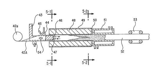
Fig. 5 is a sectional diagram of an apparatus for producing
a fiber-:reinforced thermoplastic resin foamed product used in
Example 5:
Fig. 5-1 is a sectional view of a heating mold taken along a
line (5-1.) - (5-1) in Fig. 5;
Fig. 5-2 is a sectional view of the heating mold taken
:LO along a line (5-2) - (5-2) in Fig. 5;
Fig. 5-3 is a sectional view of a hollow member obtained by
shaping a composite sheet into an ellipse at an entrance of the
heating mold:
Fig. 6 is a sectional diagram of an apparatus for producing
a fiber-reinforced thermoplastic resin foamed product used in
Example Ei ;
Fig.. 7 is a sectional diagram of an apparatus for producing
a fiber-reinforced thermoplastic resin foamed product used in
Example ;~ ;
Fig.. 8 is a sectional diagram of an apparatus for producing
a composite used in Comparative Example 1;
Fig.. 9 is a sectional diagram of an apparatus for producing
a fiber-reinforced thermoplastic resin foamed product used in
Comparat:LVe Example 2 ;
Fig. 10 is a sectional diagram of an apparatus for
producing a fiber-reinforced thermoplastic resin foamed product
used in Example 15;
5
213~~2~
Fig. 11 is a sectional diagram of an apparatus for
producing a fiber-reinforced thermoplastic resin foamed product
used in :Example 17;
Fig. 12 is a sectional diagram of an apparatus for
producing a composite foamable sheet used in Example 19;
Fig. 13 is a sectional diagram of an apparatus for
producing a fiber-reinforced thermoplastic resin foamed product
used in Example 19;
Fig. 14 is a section view of a heating mold taken along a
line 14-14 in Fig. 13;
Fig. 15 is a section view of the heating mold taken along a
line 15-15 in Fig. 13;
Fig. 16 is a section view taken along a line 16-16 in Fig.
13:
Fig'. 17 is a partial cross section view of a shaping mold of
an apparatus for producing a fiber-reinforced thermoplastic resin
sheet used in Example 20;
Figs. 18 is a sectional diagram of an apparatus for
producing a fiber-reinforced thermoplastic resin foamed product
used in Example 10;
Fic~. 18-1 is a section view of a state where a fiber-
reinforced thermoplastic resin sheet has been inserted into a
slit member 130, taken along a line (18-1) - (18-1) in Fig. 18:
Fic~. 18-2 is a section view of a state where a fiber
2~; reinforc:ed thermoplastic resin sheet has been inserted into a
slit member 131, taken along a line (18-2) - (18-2) in Fig. 18;
Fig. 18-3 is a section view of a state where a fiber-
6
~1~~~2~
reinforced thermoplastic resin sheet has been inserted into a
slit member 133, taken along a line (18-3) - (18-3) in Fig. 18;
Fig. 18-4 is a section view of a state where a fiber-
reinforced therm oplastic resin sheet has been inserted into a
slit member 134, taken along a line (18-4) - (18-4) in Fig. 18;
Fig. 18-5 is a section view of an outlet portion of a
heating mold 140 taken along a line (18-5) - (18-5) in Fig. 18;
Fig. 18-6 is a view for showing a sectional shape of a
hollow member at an inlet port of a heating mold;
Fig. 19 is a view showing a sectional shape of the hollow
member at: an inlet
port of a heating mold
in Example 18;
Fig.. 20 is a view for showing a sectional shape of the
hollow mE~mber at the inlet port of a heating mold in Example 22;
and
Fig.. 21 is a sectional diagram of an apparatus for
producing a fiber-reinforced thermoplastic resin foamed product
used in Example 22.
Detailed Description of Preferred Embodiments
To begin with, first to tenth aspects of the present
invention are explained hereunder.
The first aspect of the invention comprises a process for
continuously shaping at least one fiber-reinforced thermoplastic
resin sheet into a hollow member, and a process for supplying a
foamable resin composition, while foaming, into an inner surface
of the hollow member so that the hollow member can be shaped into
a desired form by a foaming pressure.
7
X135322
The second aspect of the invention comprises a process for
continuously shaping at least one fiber-reinforcing
thermoplastic resin sheet into a hollow member, and a process
for supplying a foamable resin composition to an inner surface of
the hollow member and heating the foamable resin composition to a
temperature higher than a foaming temperature of a foaming agent,
so that t:he hollow member can be shaped into a desired form by a
foaming pressure.
The third aspect of the invention comprises a process for
continuously shaping at least one composite sheet comprising a
fiber-reinforced thermoplastic resin layer and a foamable resin
composition layer into a hollow member so that the fiber
reinforced thermoplastic resin layer becomes an outer layer
thereof, and a process for foaming the foamable resin composition
layer so that the hollow member can be shaped into a desired form
by a foaming pressure.
The fourth aspect of the invention comprises a process for
continuously shaping at least one fibrous sheet into a hollow
member, and a process for supplying a foamable resin
composit:i.on, while foaming, to an inner surface of the hollow
member so that the hollow member can be shaped into a desired
form by a foaming pressure.
The fifth aspect of the invention comprises a process for
continuously shaping at least one fibrous sheet into a hollow
25, member, and a process for supplying a foamable resin composition
to an inner surface of the hollow member and heating the foamable
resin composition to a temperature higher than a foaming
8
~;~3~32~
temperature of a foaming agent so that the hollow member can be
shaped into a desired form by a foaming pressure.
The sixth aspect of the invention comprises a process for
continuously shaping at least one fiber-reinforced thermoplastic
resin sheet into a hollow member, a process for forming the
hollow member into a certain shape in its cross section under a
vacuum forming and/or an air pressure forming, and a process for
supplying a foamable resin composition comprising a thermoplastic
resin and a foaming agent, while foaming, to wn inner surface of
1C~ the hollow member so that the hollow member can be shaped into a
desired form by a foaming pressure.
The seventh aspect of the invention comprises a process for
continuously shaping at least one fiber-reinforced thermoplastic
resin sheet into a hollow member, a process for subjecting the
hollow member to a vacuum forming and/or an air pressure forming
so that 'the hollow member is formed into a predetermined shape in
its cross section, and a process for supplying a foamable resin
composition comprising a thermoplastic resin and a foaming agent
to an inner surface of the hollow member formed by the vacuum
2C) forming and/or the air pressure forming and heating the foamable
resin composition to a temperature higher than a foaming
temperature of the foaming agent so that the hollow member can be
shaped into a desired form by a foaming pressure.
The eighth aspect of the invention comprises a process for
continuously shaping at least one composite sheet comprising a
fiber-reinforced thermoplastic resin layer and a foamable resin
composition layer into a hollow member so that the fiber-
9
CA 02135322 2000-03-06
reinforced thermoplastic resin layer becomes an outer layer, a
process for subjecting the hollow member to a vacuum forming
and/or an air pressure forming so that the hollow member is
formed into a predetermined shape in its cross section, and a
process for foaming the foamable resin composition layer so that
the hollow member can be shaped into a desired form by a foaming
pressure.
The ninth aspect of the invention comprises a process for
continuously shaping at least one fiber-reinforced thermoplastic
:LO resin sheet in which a large number of continuous fibers are
oriented, into a hollow member so that the continuous fibers are
arranged in a longitudinal direction, a process for supplying the
hollow member into a mold, and a process for supplying a foamable
resin composition comprising a thermoplastic resin and a foaming
:L5 agent, while foaming, into an inner surface of the hollow member
and drawing out the hollow member so that the hollow member can
be shaped into a desired form by a foaming pressure.
The tenth aspect of the invention comprises a process for
continuously shaping at least one fiber-reinforced thermoplastic
,20 resin sheet in which a large number of continuous fibers are
oriented, into a hollow member so that the continuous fibers are
arranged in a longitudinal direction, a process for supplying the
hollow member into a mold, and a process for supplying a foamable
resin composition comprising a thermoplastic resin and a foaming
25 agent into an inner surface of the hollow member, heating the
foamable resin composition to a temperature higher than a
foaming temperature of the foaming agent and drawing out the
X13 ~3~2
hollow member so that the hollow member can be shaped into a
desired form by a foaming pressure.
In the present invention, as a thermoplastic resin to be
used for the fiber-reinforced thermoplastic resin sheet, though
5~ the resin is not specifically limited, for example, polyvinyl
chloride, chlorinated polyvinyl chloride, vinyl chloride-vinyl
acetate copolymer, vinyl chloride-acrylic acid copolymer,
polyethylene, polypropylene, polystyrene, polyamide,
polycarbonate, polyphenylene sulfide, polysulfone and
1G polyethe:retherketone, polymethyl methacrylate, and in addition, a
thermoplastic elastomer and the like are mentioned. Also, the
thermoplastic resin for the fiber-reinforced thermoplastic resin
sheet includes a copolymer, a modified resin and a blend resin
containing the above thermoplastic resin as a main component.
1~; For example, an ethylene-vinyl chloride copolymer, a vinyl
acetate--vinyl chloride copolymer, silane modified polyethylene,
acrylic acid modified polypropylene and so on are mentioned. In a
shaping process, the fiber-reinforced thermoplastic resin sheet
is sometimes required to be stretched. In such a case, it is
preferable to use a thermoplastic resin having a good
stretchability, or a cross-linking treatment may be applied
properly to the fiber-reinforced thermoplastic resin in order to
improve the stretchability thereof. In view of the cost,
polyvinyl chloride, polypropylene or polyethylene is preferred.
It is preferable to use a thermoplastic resin having a
melt viscosity of 1x10⁵ - 1x10 poise since an unevenness in a
thickness of the surface layer hardly occurs.
11
CA 02135322 2000-03-06
Incidentally, in the present invention, the "melt
viscosity" means an apparent viscosity in a flow tester (Koka
type flow tester) when a thermoplastic resin is extruded through
a nozzle with a diameter of 1 mm and a length of 10 mm, at a rate
of 150 kg/cm2 and at a temperature where thermal fusion is
possible.
The thermoplastic resins as mentioned above can be used
solely or as a mixture thereof. An additive, a filler, a
processing aid and a modifier, such as a heat stabilizer,
plasticizes, lubricant, antioxidant, ultraviolet absorber,
pigment, inorganic filler and reinforcing short fibers, may be
added to the thermoplastic resin.
As fibers to be used for the fiber-reinforced thermoplastic
resin sheet, any fibers usable as reinforcing fibers, for
example, inorganic fibers, such as glass fibers, carbon fibers
and metal fibers; synthetic fibers, such as alamide fibers and
vinylon; and natural fibers, such as silk, cotton and linen, can
be used.
As the fibers, in order not to damage the surface
smoothness of an obtained fiber-reinforced thermoplastic resin
sheet while maintaining its impact resistance, it is preferable
to use long fibers or continuous fibers with a diameter of 1-
100 micro meters and a length of 10 mm or longer. A fiber state
in the fiber-reinforced thermoplastic resin sheet is not limited
to a specific form. For example, a mat form where long fibers
are oriented at random; a roving form, strand form and cloth form
comprising continuous fibers; a form where respective continuous
12
2.35322
fiber filaments are arranged in a longitudinal direction of a
composite and branched in an open state; or a combination of a
plurality of the fibers in the above-mentioned forms, can be
mentioned.
G; The fiber-reinforced thermoplastic resin sheet to be used in
the present invention can be produced, for example, as follows,
though its production is not limited to a certain method.
In case a fiber-reinforced thermoplastic resin sheet having
a state 'where fibers are arranged in one direction is produced, a
1(1 thermoplastic resin in a powder form is supplied into a
fluidiz_Lng tank, and air is ejected thereinto through a
perforated plate provided at a bottom of the tank to thereby
fluidize the thermoplastic resin. A plurality of fiber bundles
guided by guide rollers is passed through the fluidizing resin to
1'. obtain thermoplastic resin adhered fiber bundles, and the thus
obtained fiber bundles are passed through heating rollers so that
the the~__~moplastic resin is permeated into and adhered to the
fibers. Finally, the fibers with the thermoplastic resin are
passed through cooling rollers to obtain a desired fiber-
2C~ reinforced thermoplastic resin sheet.
Also, in case a fiber-reinforced thermoplastic resin sheet
where fibers are oriented at random is produced, the fiber
bundles with the thermoplastic resin obtained as explained above
are cut into pieces by a rotary cutter to fall onto a lower
2~~ endless belt and collected. The pieces are passed through a
heating furnace while being pressed between endless belts so that
the cut fibers are permeated with the thermoplastic resin, and
13
213322
then passed through cooling guide rollers to obtain a desired
fiber-reinforced thermoplastic resin sheet.
Also, in case a thermoplastic resin having a low melt
viscosity is used, the thermoplastic resin in a molten state is
soaked :into the fibers to thereby obtain a thermoplastic resin
sheet. In such a case, it is preferable to cross-link the
thermoplastic resin after a fiber-reinforced thermoplastic resin
sheet i:c produced .
In case a hollow member is shaped into a predetermined form
by a vacuum forming or an air pressure forming, in order to
improve airtightness and shaping ability of the hollow member, in
the manufacturing method as mentioned above, it is preferable
that the fiber bundles are permeated with the thermoplastic resin
beforehand, or a surface treatment is made to the obtained fiber
reinforced thermoplastic resin sheet, so that the contact of the
fibers and the thermoplastic resin is improved.
Incidentally, the fiber-reinforced thermoplastic resin
sheet may be a single layer, or a laminate structure formed of a
pluralii~y of the fiber-reinforced thermoplastic resin sheets.
Although the thickness of the fiber-reinforced
thermoplastic resin sheet is not limited, when the fiber-
reinforced thermoplastic resin sheet is thin, the reinforcing
effect can not be obtained, and when it is thick, it is
difficu:Lt to shape the sheet into the hollow member. Therefore,
the thickness in a range fram 0.1 to 10 mm is preferable. When
an amount of the fibers contained in the fiber-reinforced
thermop:Lastic resin sheet is small, the sufficient reinforcing
14
CA 02135322 2000-03-06
effect and forming stability can not be obtained, and if the
amount is large, the fibers can not be permeated with the
thermoplastic resin so that fuse bonding becomes difficult, and
the reinforcing effect is decreased. In addition, in case the
hollow member is subjected to the vacuum forming and/or the air
pressure forming, when the airtightness is decreased, the hollow
member can not be shaped sufficiently. Therefore, it is
preferable that the amount of the fibers contained in the fiber-
reinforced thermoplastic resin sheet is in a range from 5 to 70
volume %, more preferably from 10 to 50 volume
The fiber-reinforced thermoplastic resin sheet is formed
into a hollow member, and the hollow member is shaped by a
vacuum forming, an air pressurefo.rming,or a foaming pressure. In
that case, the hollow member may be regulated by a regulating
member, such as a mold, from the outside, so that friction force
is generated between the regulating member and the fiber-
reinforced thermoplastic resin sheet.
Therefore, when a draw forming is carried out against the
friction force, in order to prevent the fiber-reinforced
thermoplastic resin sheet from being cut off, it is preferable to
use a fiber-reinforced thermoplastic resin sheet where the
continuous fibers are arranged in a longitudinal direction
thereof. Incidentally, when a plurality of the fiber-reinforced
thermoplastic resin sheets is laminated, it is sufficient that
one of the sheets has the fiber-state as mentioned above.
When a composite sheet comprising a foamable resin
composition layer laminated on one surface of the fiber-
2135322
reinfor~~ed thermoplastic resin layer comprising the above
mentioned fiber-reinforced thermoplastic resin sheet is used as a
substitute for the fiber-reinforced thermoplastic resin sheet,
gas generated from the foamable resin composition is prevented
from penetrating into an interface between the surface layer and
the core layer of the obtained fiber-reinforced thermoplastic
resin foamed product. Thus, it is possible to prevent voids from
forming between the surface layer and the core layer of the
obtained fiber-reinforced thermoplastic resin foamed product, and
to obtain the fiber-reinforced thermoplastic resin foamed product
excellent in the fuse-bonding between the surface layer and the
core layer.
The: foamable resin composition layer comprises the same
substance as a foamable resin composition which is supplied to
the innE~r surface of the hollow member in an unfoamed state, as
describE:d hereunder .
As in the fiber-reinforced thermoplastic resin sheet, the
composite sheet may be used singly or in a laminate structure
formed of a plurality of the composite sheets.
ThE: method for producing the composite sheet is not limited
to a specific way. For example, there are methods, wherein a
foamablE: resin composition sheet prepared beforehand is heated
and fuse-bonded on one surface of the fiber-reinforced
thermoplastic resin sheet obtained as described above to thereby
obtain a composite sheet; and wherein a foamable resin
composii~ion in an unfoamed condition is extruded in a sheet form
onto one surface of the fiber-reinforced thermoplastic resin
16
X13 i~~2
sheet obtained as described above to thereby obtain a composite
sheet.
A fibrous sheet may be substituted for the fiber-
reinforced thermoplastic resin sheet. In case the fibrous sheet
is used, when the hollow member is shaped by a foaming pressure
of the foamable resin composition, the fibrous sheet can be
permeated with the foamable resin composition, so that the fiber-
reinforced thermoplastic resin sheet need not be prepared
beforehand thus to eliminate the process.
liJ As the fibers to be used for the fibrous sheet, any fibers
can be used if the fibers do not melt at a melting temperature of
the thermoplastic resin for constituting the foamable resin
composition or at a foaming temperature Qf the foamable resin.
composii:ion, and are not limited to a specific fiber. For
1, example,, a glass fiber, carbon fiber, silicon fiber, titanium
fiber, carbon fiber, boron fiber, metal fiber, alamide fiber,
polyester fiber, and polyamide fiber are mentioned.
WhE~n a diameter of a mono-f i lament of the f fiber to be used
for the fibrous sheet is small, a reinforcing effect can not be
obtained. If it is large, the number of the fibers per unit area
is decreased since a weight per unit area is maintained in a
certain value not to impair its light weight. Therefore, a
contact area between the resin and the fibers is reduced and
strength of a surface layer of the obtained fiber-reinforced
thermoplastic resin foamed product is decreased. Thus, the
diameter of the mono-filament is, preferably, in a range from 1
to 50 micro meters, and, more preferably, from 3 to 23 micro
17
CA 02135322 2000-03-06
meters.
The "fibrous sheet" means that the fibers are piled or
assembled together into a sheet form, and preferable examples
are long fibers or continuous fibers bound with a little amount
of binding agent, such as a continuous mat, swirl matte,
chopped strand mat, and fiber cloth and the like.
When a percentage of voids in the fibrous sheet is small,
the fibrous sheet is not sufficiently permeated with a resin due
to foaming of the foamable resin composition, so that the surface
layer thereof tends to be peeled from the core layer. While if
the percentage is large, the reinforcing effect by the fibers is
decreased. Therefore, the percentage of voids is preferable in a
range from 5 to 15 volume %.
Incidentally, when the hollow member is shaped, the hollow
member may be stretched as a whole or partially. In such a case,
the hollow member may be cracked or is thinned partially, so that
the surface layer of the obtained fiber-reinforced thermoplastic
resin foamed product tends to have portions where rigidity is
partially decreased. In order to prevent the problem, when the
above fiber-reinforced thermoplastic resin sheet or the fibrous
sheet is used, a highly stretchable thermoplastic resin layer may
be laminated onto the outer or inner surface of the hollow
member, and in case the composite sheet is used, the stretchable
layer may be laminated on the outer surface of the hollow member.
Especially, it is preferable to laminate the thermoplastic
resin layer onto the outer surface of the hollow member since the
obtained fiber-reinforced thermoplastic resin foamed product is
18
2135322
improved in its smoothness of the surface layer in addition to
the above-mentioned effects.
Also, in case the hollow member is subjected to a vacuum
forming and/or an air pressure forming, airtightness of the
hollow member is improved by laminating the thermoplastic resin
layer as described above to thereby improve shaping of the hollow
member.
A method for shaping the fiber-reinforced thermoplastic
resin sheet, the composite sheet and the fibrous sheet into the
hollow member, is not specifically limited. For example, in
addition to methods using a mold as explained later in
embodiments, there is a method where the sheet is gradually bent
by using a shoe or rollers made of a synthetic resin or metal.
When a sheet is shaped into a hollow form, in order to prevent
the fiber-reinforced thermoplastic resin sheet, the composite
sheet or, the fibrous sheet from being cracked or torn, it is
preferable to shape the thermoplastic resin in a soft state,
while hs:ating by an infrared ray heater or a hot air blower.
Incidentally, the "hollow member" in the present invention
includes a hollow member where both ends have a space
therebetween, in addition to a hollow member where both ends abut
against each other or are overlapped each other.
In case the hollow member is subjected to an air pressure
formation, when a thermoplastic resin having a high melt
viscosity is used for the fiber-reinforced thermoplastic resin
sheet or the composite sheet, and both ends of the hollow member
are joined by melting the thermoplastic resin in a process of
19
CA 02135322 2000-03-06
shaping into the hollow member, even if both ends of the hollow
member abut against each other, there is no problem of lowering a
shaping ability in the vacuum forming and/or the air pressure
forming. Otherwise, it is preferable to overlap both ends with
each other so that the airtightness and shaping ability of the
hollow member are improved.
Also, when the fiber-reinforced thermoplastic resin sheet,
the composite sheet and the fibrous sheet are shaped into the
hollow member, a plurality of the fiber-reinforced thermoplastic
resin sheets and the like may be used so that the respective ends
of the sheets abut against or overlap with each other to shape
the hollow member.
Especially, in case the whole circumference with a desired
cross section becomes larger than that of the hollow member when
shaped by the vacuum forming and/or the air pressure forming or
foaming pressure, the respective ends of the plural fiber-
reinforced thermoplastic resin sheets and the like are overlapped
by the length to be elongated on the elongated portion in a
shaping process to shape the hollow member. As a result, the
overlapped portions are moved when elongated, and the respective
fiber-reinforced thermoplastic resin sheets are elongated
gradually. Therefore, an elongating degree of the respective
fiber-reinforced resin sheets for the hollow member becomes
smaller when compared with that of one fiber-reinforced
25 thermoplastic resin sheet for the hollow member.
Therefore, by overlapping the respective both ends of the
plural fiber-reinforced thermoplastic resin sheets to shape a
~13~3~2
hollow member, the surface layer is prevented from being thinned,
so that rigidity of the obtained fiber-reinforced thermoplastic
resin foamed product is not decreased. At the same time, it is
possiblE: to prevent the surface layer from being thinned
partially by partial enlargement of the hollow member in the
shaping process of the hollow member, and the fiber-reinforced
thermoplastic resin foamed product has preferably a uniform
rigidity as a whole.
The: first, second, fourth, fifth, ninth and tenth aspects of
the invention are characterized by shaping the hollow member
obtained as described above into a desired form by a foaming
pressure; the sixth and seventh aspects of the invention are
characterized by shaping the hollow member obtained as described
above into a desired form by a vacuum forming and/or air pressure
forming and the foaming pressure; the third aspect of the
invention is characterized by foaming the foamable resin
composition layer of the hollow member obtained as described
above, and shaping it into a desired form by the foaming
pressure; and the eighth aspect of the invention is characterized
by shaping the hollow member obtained as described above into a
desired form by the vacuum forming and/or the air pressure
forming and the foaming pressure.
It is needless to say that the "air" in the air pressure
forming includes a gas, such as nitrogen gas in addition to so
called "atmospheric air".
In the sixth to eighth aspects of the invention, in case
the hollow member is shaped by the foaming pressure of the
21
~i3~~~2
foamable resin composition as well as the vacuum forming and/or
the air pressure forming, when comparing with a case where the
hollow member is shaped by only the foaming pressure, preferably
it is possible to obtain a fiber-reinforced thermoplastic resin
foamed product having a complicated cross section, especially an
accurate cross section.
A foamable resin composition to be used in the invention
includes a thermoplastic resin and a foaming agent.
As the thermoplastic resin, there are mentioned any
thermoplastic resins which are foamable, for example, polyvinyl
chloride, chlorinated polyvinyl chloride, polyethylene,
polypropylene, polystyrene, polyamide, polycarbonate,
polyphenylene sulfide, polysulfone, polyetheretherketone and the
like. However, when compared with the thermoplastic resins to be
used for the fiber-reinforced thermoplastic resin sheet, in a
formation temperature region, resins having a good fluidity with
a relatively lower viscosity can be preferably used to prevent
uneven foaming and to improve uniformity of a thickness of the
surface layer of the fiber-reinforced thermoplastic resin foamed
2 p product. .
Incidentally, the thermoplastic resin to be used for the
fiber-reinforced thermoplastic resin sheet as a surface layer
and the thermoplastic resin to be used for a foamable resin
composition need not be the same. Combination of the resins is
not specifically limited provided that when both resins are
heated to a molten state, i.e. a state where a heat fusion-
bonding is possible, and press-contacted, an interface between
22
213322
the fuse-bonded resins is not easily detached after they are
cooled down.
However, in case the fibrous sheet is used, when a melt
viscosity of the thermoplastic resin to be used as the foamable
resin composition is high, it is difficult to permeate the resin
between the fibrous sheets, while if it is low, bubbles of the
obtained foamed member does not become uniform and fine.
Therefore, it is preferable that the melt viscosity of the
thermoplastic resin is in a range from 6,000 to 30,000 poise.
Incidentally, the thermoplastic resin to be used for the
foamable resin composition may be used singly or as a mixture of
a plurality of resins. Further, in a range where the foaming
ability of the foamable resin composition is not damaged,
additives, fillers, processing aids and modifiers, such as a heat
stabilizer, plasticizer, lubricant, antioxidant, ultraviolet
absorber., pigment, inorganic filler and reinforcing fibers may be
added thereto.
In view of recycling, waste plastic, woody material, wood.
powder, sheet molding compound crushed powder and the like are
preferably used.
In case the reinforcing fibers are added to the resin, when
an amount of the fibers is small, a satisfactory reinforcing
effect can not be obtained, while if the amount is large, it is
difficult to uniformly foam the foamable resin composition to
thereby decrease the reinforcing effect, on the contrary.
. Therefore, the amount of the reinforcing fibers is in a range
from 5 to 60 volume %, and, more preferably, from 20 to 30 volume
23
~135i32~
of the foamable resin composition.
Further, a cross-linking treatment may be applied in order
to improve the foaming ability.
The cross-linking treatment is not limited to a specific
method. For example, there are cross-linking methods where
cross-linking is carried out by irradiating an activation energy
ray, such as a visible light, ultraviolet ray, alpha ray, beta
ray, gamma ray, X ray or electron beam; where an organic peroxide
is added thereto to decompose; where a cross-linking silane
modified thermoplastic resin is added thereto and the mass is
subjected to a water treatment; and the like.
As a thermoplastic resin to be able to cross-link by an
electron beam, for example, a thermoplastic resin having an
alpha-hydrogen, such as polyethylene, polypropylene, polystyrene
and the like, is mentioned. Also, as a thermoplastic resin to be
able to cross-link by the visible light and ultraviolet ray, a
thermoplastic resin, if necessary, containing a light
polymerization initiator (photosensitizer) is mentioned. As the
light polymerization initiator, for example, benzoinalkylether
2d series, acetophenone series, benzophenone series, thioxanthone
series and the like, are mentioned.
Also, as the organic peroxide, which is not specifically
limited, for example, isobutyl peroxide, dicumyl peroxide, 2,5-
dimethyl-2,5-di(t-butylperoxide)hexene, 1,3-bis(t-
butylperoxyisopropyl)benzene, t-butylcumylperoxide, di-t-
butylperoxide and the like, are mentioned.
In this case, although the thermoplastic resin itself tends
24
CA 02135322 2000-03-06
to be, generally, torn by adding the organic peroxide, in case
the thermoplastic resin is not cross-linked to a desired extent,
a cross-linking agent, such as triallylcyanulate and
diallylphthalate, may be suitably added thereto.
The foaming type agent, which is not limited to a specific
one, includes a gas in addition to a decomposing foaming agent
which decomposes to generate a gas, and a physical-type foaming
agent which generates a gas by evaporation. As the decomposing
type foaming agent, for example, azodicarbonamide,
azobisisobutyronitrile, N,N'-dinitropentamethylenetetramine, p,p~-
oxybisbenzenesulfonylhydrazide, azodicarboxylic acid barium,
trihydrazinotriazine and 5-phenyltetrazole are mentioned.
As the physical type foaming agent, for example, an
aliphatic hydrocarbon, such as isopentane, heptane and cyclohexane;
and an aliphatic hydrocarbon fluoride, such as
trichlorotrifluoroethane and dichlorotetrafluoroethane are
mentioned.
As the gas, for example, air, nitrogen and helium are
mentioned.
When a foaming expansion ratio in the obtained foamed member
is high, rigidity of the obtained foamed member for constituting
the core layer is decreased. Therefore, the foaming agent is
preferably mixed to foam in a range of 30 times or less, preferably
between 1.5 and 5 times.
Specifically, in case of the decomposing type foaming agent
and the physical-type foaming agent, though an amount to be added
varies depending on a kind of the foaming agent, it is
25
X133322
preferable to add 1 to 20 parts by weight of a foaming agent.
with respect to 100 parts by weight of a thermoplastic resin.
In the present invention, in case the fiber-reinforced
thermoplastic resin or fibrous sheet is used without using a
composite sheet, although it is required to supply the foamable
resin composition, the foamable resin composition may be supplied
into an inner surface of the hollow member while foaming or in an
unfoamed state.
As a method of supplying the foamable resin composition
while foaming, for example, there are a method wherein after a
foamable resin composition is prepared by kneading or permeating
a foaming agent into the thermoplastic resin at a temperature
lower than a foaming temperature, the thus obtained foamable
resin composition is fed into an extruder and heated to a
temperature higher than the foaming temperature, which is
supplied while foaming: and a method wherein a thermoplastic
resin is supplied into an extruder and melt-kneaded therein to
obtain a thermoplastic resin in a molten state, and the molten
thermoplastic resin is supplied while foaming by supplying a
physical-type foaming agent or a gas thereto from a middle part
of the extruder.
Incidentally, in the present invention, the "foaming
temperature" means a decomposition temperature in case of a
decomposition foaming agent, and a boiling temperature in case of
a physical type foaming agent. Incidentally, the "decomposition
temperature" means a temperature at which a decomposition degree
is reduced to a half in three minutes. However, it is needless
26
CA 02135322 2000-03-06
to say that the foamable resin composition is in a foamable state
at the foaming temperature.
In case of a decomposing type foaming agent, it is
preferable to heat the foaming agent at the decomposition
temperature with a fraction of +/- 20°C. If the temperature
exceeds +20°C
relative to the decomposition temperature, dregs decomposes as
well. Thus, the amount of the gas generated by the foaming agent
can not be constant, so that the shaping ability decreases. On
the other hand, if the temperature is less than -20°C relative
to the decomposition temperature, a time required to generate the
gas increases, so that the productivity decreases.
In case of a physical type foaming agent, it is required to
simply heat the foaming agent more than the boiling temperature.
There is no preferable range for the heating temperature.
Next, as a method for supplying a foamable resin
composition in an unfoamed state, for example, there is a method
wherein after the foamable resin composition is prepared by
kneading or permeating a foaming agent into a molten
thermoplastic resin at a temperature lower than a foaming
temperature of the foaming agent, the thus obtained foamable
resin composition is supplied in a desired form, such as a
pellet, sheet, rod and pipe.
The foamable resin composition is not necessary to be
supplied in a quantity which fully fills an inside of the hollow
member, when foamed. since the hollow member is regulated by a
regulating member for a mold to thereby obtain a desired shape,
it is sufficient to supply a quantity of the foamable resin
27
~13~3~2
composition in which the hollow member is pushed against the
regulating member made of metal and so on by the foaming
pressure. For example, a mold core is extended to a mold cooling
position to regulate foaming so that a product finally obtained
may have spaces at various portions. Or, by varying a supplying
quantity of the foamable resin composition or a speed of drawing
of the hollow member, portions fully filled with foam and
portions not fully filled with foam may be formed in the core
layer of the obtained fiber-reinforced thermoplastic resin foamed
product.
In the present invention, the "foaming pressure" includes
not only a forming pressure generated by only the foamable resin
composition but also an additional pressure separately applied to
an interior when sufficient pressure can not be obtained by only
the foamable resin composition to push the hollow member against
the regulating member.
In case the additional pressure is applied to the interior,
it is preferable to employ a structure, where an air piping is
provided through the interior of the regulating member so that a.
gas can be supplied into the hollow member.
As a method for foaming an unfoamed foamable resin
composition supplied into the interior of a hollow member, which.
is not specifically limited, for example, there is a method
wherein hot air is blown from an interior and/or an outer portion
of the hollow member. Incidentally, when the foamable resin
composition is supplied while foaming, if necessary, the hollow
member may be heated.
28
213322
The hollow member is shaped into a desired form with a
foaming pressure generated by foaming of the foamable resin
composition, and the method for shaping into a desired form is
not limited to a specific one. For example, there are a method
wherein a hollow member is supplied into a regulating member,
such as a mold having a desired form in the cross section, and a
fiber-reinforced thermoplastic resin sheet and the like is
pressed against the regulating member to shape into a desired
form by the foaming pressures and a method wherein, depending on
a shape of the finally obtained fiber-reinforced thermoplastic
resin foamed product, a regulating process by the, regulating
member is not carried out, and the hollow member is shaped by the
foaming pressure.
When a foaming expansion ratio of the inner core layer
becomes more than 30 times, the foaming layer itself can not
hold the stress and its rigidity is decreased. Therefore,
although the foaming expansion ratio is preferably less than 30
times, in combination with reinforcing fibers an optimum rate can
be suitably selected. A range of from 1.5 to 5 times is more
preferable.
In case a fibrous sheet is used, a foamable resin
composition is permeated into fibers while foaming. In order to
obtain a core layer having a high foaming expansion ratio, when a
thermoplastic resin of a high viscosity for constituting the
2.5 foamable resin composition is used, the thermoplastic resin may
be hardly permeated into the fibers. In such case, it is
preferable that a regulating member for regulating a hollow
29
CA 02135322 2000-03-06
member is gradually made small in its cross section, so that the
molten thermoplastic resin can be easily permeated into
fibers.
Specifically, for example, after the fibrous sheet is
continuously shaped into a hollow member, a foamable resin
composition is supplied to an inner surface of the hollow
member, and the foamable resin composition is foamed in a mold.
At the same time, the fibrous sheet is oriented toward the inner
surface to have a small cross section, so that the thermoplastic
resin for constituting the foamable resin composition is readily
permeated into the fibrous sheet.
In an eleventh aspect of the invention, it includes a
process wherein at least one fiber-reinforced thermoplastic
resin sheet partially laminated in a width direction,
is continuously shaped into a hollow member, a
process wherein a composite foamable sheet comprising a fibrous
material containing fibers as a principal component and permeated
with a foamable resin composition is supplied into the hollow
member to thereby integrally unite with each other; and a process
wherein the hollow member is subjected to a vacuum forming and/or
an air pressure forming, and at the same time the foamable resin
composition is heated to a temperature higher than a foaming
temperature of the foaming agent so that the hollow member is
enlarged and thickened.
In the eleventh aspect, the same fiber-reinforced
thermoplastic resin sheet as described before is used.
A process where a single or a plurality of the fiber-
30
CA 02135322 2000-03-06
reinforced thermoplastic resin sheets partially laminated in a
width direction is continuously shaped into a hollow member, and
a shape of the obtained hollow member, is the same as those
described above.
A composite sheet used in the eleventh aspect comprises a
fibrous material containing fibers as a principal component and a
foamable resin composition permeated into the fibrous material.
The fibrous material containing fibers as a principal
component is not limited to a specific one. The fibrous
material may contain the foamable resin composition slightly
more than that used in the outer or surface layer of the fiber-
reinforced thermoplastic resin foamed product. For example, a
swirl mat, continuous mat, chopped strand mat and the like
are mentioned.
When a length of the fibers constituting the fibrous
material is short, the fibers are not entangled each other, so
that the fibrous material can not hold its shape. If it is long,
when the hollow member is enlarged and thickened, it is difficult
to preferentially orient the fibers in one direction. Therefore,
2p it is preferable that the fibers have a length in a range of from
5 to 100 mm.
When a diameter of the fibers for constituting the fibrous
material is small, reinforcing effect is decreased. When it is
large, formation into the fibrous material is difficult.
Therefore, the diameter is preferably in a range from 1 to 50
micro meters, and more preferably, in a range from 7 to 23 micro
meters.
31
~1~a~22
A foamable resin composition used in the eleventh aspect is
the same as those explained in the first aspect.
A method for producing the composite foamable sheet is not
limited to a specific one. For example, there are a method
wherein a molten foamable resin composition is supplied to the
fibrous material at a temperature lower than a foaming
temperature and pressurized so that the molten foamable resin
composition is permeated into the fibrous material to thereby
obtain the composite foamable sheet; and a method wherein after a
ld powdery foamable resin composition is supplied into the fibrous
material by vibrations or air, the powdery foamable resin
composition is melted and permeated into the fibrous material at
a temperature lower than a foaming temperature.
In the eleventh aspect, the composite foamable sheet is
supplied into an interior of the hollow member to thereby
integrate with each other. The integrating method is not
limited to a specific one. For example, there are a method
wherein after the hollow member provided with the composite
foamable sheet therein is supplied into a mold where an outlet in
its cross section is smaller than an inlet in its cross section
in a tapered state, the mold is held at a temperature higher than
a melting temperature of the thermoplastic resin to be used for
the hollow member or a thermoplastic resin to be used for the
composite foamable sheet, and at a temperature lower than a
foaming temperature of a decomposition foaming agent to thereby
integrate with each other; and a method wherein the hollow member
is pushed from the outside by a regulating member maintained at a
32
X135322
temperature higher than a melting temperature of the
thermoplastic resin to be used for the hollow member or of the
thermoplastic resin to be used for the composite foamable sheet,
and at a temperature lower than a foaming temperature of the
decomposition foaming agent to thereby integrate with each other.
Thereafter, the hollow member integrated with the composite
foamable sheet is subjected to the vacuum forming and/or air
pressure forming, and the foamable resin composition is heated to
a temperature higher than a foaming temperature of the foaming
agent, so that the hollow member is enlarged and thickened.
Methods of the vacuum forming and/or the air pressure forming of
the hollow member and heating of the foamable resin composition
to the temperature higher than the foaming temperature of the
foaming agent are carried out in the same manner as described
above.
A method for enlarging and thickening the hollow member is
not limited to a specific one. For example, it is sufficient
that a thickness of the hollow member is enlarged at least in one
direction by the vacuum forming and/or the air pressure forming
and the foaming pressure. For instance, the hollow member
integrated with the composite sheet is supplied into a mold
having a cross section larger than that of the hollow member and
capable of performing the vacuum forming and/or the air pressure
forming, and is enlarged and thickened by the vacuum forming
and/or the air pressure forming and the foaming pressure. It is
preferable to enlarge the thickness only preferentially in one
33
~13~322
direction of the hollow member since the fibers are
preferentially oriented in a certain direction in the obtained
fiber-reinforced thermoplastic resin foamed product to thereby
improve a compression strength.
The obtained foaming expansion ratio of the inner core
layer is preferably the same range for the same reason as
described above, i.e. generally less than 30 times and more
preferably 2-5 times.
In the production methods of the fiber-reinforced
thermoplastic resin foamed product of the invention, as the
surface layer, the fiber-reinforced thermoplastic resin sheet
and the like is used, and is shaped into the hollow member. The
foamable resin composition is supplied into the inner surface of
the hollow member while foaming, or after the foamable resin
composition is supplied and then the foamable resin composition
is foamed, so that the hollow member is shaped by pressure of the
foamable resin composition.
Therefore, it is not necessary to prepare a foamed member
beforehand. Further, since the hollow member is shaped by the
foaming pressure, an uneven thickness of the surface layer formed
of the hollow member hardly occurs.
Since the thermoplastic resin is used for the surface layer
and the core layer and the shaping of the layers is performed by
the foaming, it is possible to shape into a desire form in a
course of production, so that a fiber-reinforced thermoplastic
resin foamed product having a complicated cross section is
obtained.
34
213322
Further, the hollow member is pushed from the inner side
with uniform force by the resin in a molten state and in a
course of foaming with a pressure of foaming of the foamable
resin composition to thereby fuse-bond the surface layer and the
core layer integrally, so that a partially less fuse-bonding
portion is not formed in an interface between the surface layer
and the core layer. Therefore, a fiber-reinforced thermoplastic
resin foamed product having a uniform quality, such as rigidity,
can be obtained.
In case the hollow member is elongated in a course of
shaping, a plurality of the fiber-reinforced thermoplastic resin
sheets is shaped into the hollow member by overlapping the
respective ends thereof so as to correspond to a portion to be
elongated. By doing so, the overlapping portions of the
respective fiber-reinforced thermoplastic resin sheets are moved,
and the respective fiber-reinforced thermoplastic resin sheets
are slightly elongated, so that the obtained surface layer is
alleviated to be thin, and also partially thin portion is not
formed in the surface Layer.
Also, by using the composite sheet, since a gas generated
from the foamable resin composition does not remain in an
interface between the surface layer and the core layer, voids are
prevented from being created between the surface layer and the
core layer in the obtained fiber-reinforced thermoplastic resin
foamed product.
Also, by using the fibrous sheet, the resin is permeated
into fibers of the fibrous sheet, so that the fiber-reinforced
~13~322
thermoplastic resin sheet and the like need not be produced
beforehand to thereby eliminate the process.
By shaping the hollow member by means of the foaming
pressure, the vacuum forming, the air pressure forming or the
combination thereof, an accurate fiber-reinforced thermoplastic
resin foamed product having a complicated lateral cross section
which can not be obtained by only the foaming pressure, can be
obtained.
By using the fiber-reinforced thermoplastic resin sheet
wherein many continuous fibers are oriented, and by shaping the
hollow member so that the continuous fibers are arranged in a
longitudinal direction therein, it is possible to produce the
fiber-reinforced thermoplastic resin foamed product, while
drawing out the hollow member.
By supplying the composite sheet into the hollow member to
integrate with each other, and then subjecting the integrated
unit to the vacuum forming and/or the air pressure forming to
thereby foam and enlarge the thickness of the unit, the fibers
for constituting the composite foamable sheet supplied into the
hollow member are preferentially oriented in the direction of the
enlarged thickness. Thus, the compression strength of the fiber-
reinforced thermoplastic resin foamed product can be improved.
Hereinafter, the invention is described in detail with.
reference to examples. However, the invention is not limited to
the examples. Incidentally, in the drawings, "front" means a.
right direction thereof.
36
~13~3~2
Example 1
A fiber-reinforced thermoplastic resin sheet was produced
according to a method as described below.
As shown in Fig. 1, 24 strands of glass fiber bundles 1
(4,400 tex.) in a roving form comprising filaments having a
diameter of 23 micro meters were arranged respectively in two
stages of upper and lower portions; then passed through
fluidizing tanks 3 where a powder-form resin composition 2
having a particle diameter of about 80 micro meters and
comprising 100 parts by weight of polyvinyl chloride (melt
viscosity of 2.4 x 10⁵ poise), 1 part by weight of a tin-type
heat stabilizer, and 0.5 part by weight of polyethylene WAX was
fluidized by air fed under pressure from an arrow direction to
thereby cause the powder-form resin composition 2 to adhere to
the filaments of the glass fiber bundles 1; and thereafter passed
through a heating furnace 4 heated to a temperature of about 200
oC so that the resin composition 2 was heated, pressurized and
melted to be permeated into the glass fiber bundles and to obtain
a fiber-reinforced thermoplastic resin sheet 5 having a thickness
of 1.2 mm. Also, after the respective glass fiber bundles 1 were
passed through the fluidizing tanks, a net-form glass fiber 6 was
sandwiched between the upper and lower fiber bundles 1. Content
of the glass fibers in the fiber-reinforced thermoplastic resin
sheet 5 was 30 o by volume.
An apparatus for producing a fiber-reinforced thermoplastic
resin foamed product shown in Fig. 2 comprises an unwinding roll
6' where the above-obtained fiber-reinforced thermoplastic resin
37
z1~~32~
sheet 5 with a width of 91 mm and a thickness of 1.2 mm is wound;
an extruder 7 for extruding a foamable resin composition; a mold
8 disposed in front of the extruder 7, and having an apex portion
bent to make a right angle in front thereof, a circular hole for
supplying a foamable resin composition and located in the
central portion thereof, and a space for shaping the sheet 5
into a circular shape; an inner core 9 fixed to a rear end
portion of the mold 8 to project forwardly and having a circular
shape in a vertical cross section; a heat-insulating material 10
provided in front of the mold 8; a heating mold 11; a heat-
insulating material 12; a cooling mold 13; and a drawing machine
14 provided in front of the cooling mold 13. A vertical cross-
sectional shape of the heating mold 11 is a circle having a
diameter of 29 mm. The heat-insulating material 12 in front of
the heating mold 11 and the cooling mold 13 have the same cross-
sectional shape.
A U-shape clearance for inserting the fiber-reinforced
thermoplastic resin sheet 5 is provided at a rear portion of the
mold 8, and the fiber-reinforced thermoplastic resin sheet 5 was
inserted through the clearance into the mold 8 where the sheet of
the U-shape was continuously shaped into a hollow member in which
both ends of the sheet 5 abut against each other without
overlapping with each other to have an outer diameter of 29.0 mm
and a thickness of 1.2 mm. A foamable resin composition 15
comprising 100 parts by weight of polyvinyl chloride, 2.5 parts
by weight of a tin-type heat stabilizer, 0.5 part by weight of a
lubricant, 8 parts by weight of an acrylic processing aid, 5
38
CA 02135322 2000-03-06
parts by weight of CaC03, 2 parts by weight of dioctyl phthalate
and 3.5 parts by weight of sodium bicarbonate (foaming
temperature of 175 °C) was beforehand kneaded and pelletized at a
resin temperature of 162 QC or lower through a twin-screw
extruder having a screw diameter of 30 mm.
The thus pelletized foaming resin composition 15 was
extruded through a single-screw extruder (L/D - 30, compression
ratio 2.5) having a screw diameter of 40 mm at a resin
temperature of 200 oC, into an interior of the above-obtained
hollow member to laminate thereto, and at the same time, was
started foaming while maintaining at the resin temperature of 200
°C by the heating mold 11. Thereafter, an outer layer surface
temperature of the hollow member was cooled by the cooling mold
13 to a temperature of 60 oC, so that a fiber-reinforced
thermoplastic resin foamed product 16 having an expansion ratio
of 3.2 times in a core layer and a diameter of 29 mm in a
circular cross section was continuously produced at a speed of
1.5 m/min.
A bending strength, flexural modulus, compression strength,
maximum and minimum values of a surface layer, and CV value of
the obtained fiber-reinforced thermoplastic resin
foamed product 16 were measured by the follow method and the
results are shown in Table 1.
The bending strength and flexural modulus were measured
according to JIS K7221.
The compression strength was measured according to a
flattening test of JIS 63448, wherein weight by which a distance
39
~13~32~
of a flat plate is reduced to a height of two thirds is divided
by an area where the flat plate and a test piece contact at the
time of the height of two third.
The maximum and minimum values of a thickness of a surface
layer were measured such that ten pieces were cut off, at random,
from the obtained fiber-reinforced thermoplastic resin foamed
product; the pieces were further divided into ten; the
thicknesses of the respective surface layers were measured; and
the maximum value and the minimum value thereof were selected.
The CV value was measured such that a standard deviation
and an average value were calculated from the above measured
values, and the CV value was obtained from the following
equation.
CV value = 100 x standard deviation/average value
Example 2
A fiber-reinforced thermoplastic resin sheet 5' was
prepared in the same manner as in Example 1 except that a net
form glass fiber 6 was not sandwiched between the glass fiber
bundles 1.
A content of the glass fiber in the fiber-reinforced
thermoplastic resin sheet 5' was 50 % by volume.
The mold 11 in the production apparatus used in Example 1
was changed to have a diameter of 29 mm in an inlet circular
cross section, a rectangle of 27 x 27 mm in an outlet shape and
an inner cross section shape of the mold where the inlet shape
was gradually changed to the outlet shape . Except the mold 11,
~13~~~?
the production apparatus used in Example 1 was not changed, and a
fiber-reinforced thermoplastic resin foamed product 16 having an
expansion ratio of 2.8 times in a core layer and a rectangular
cross section of 27 x 27 mm was continuously produced in the same
manner as in Example 1, at a speed of 1.2 m/min.
A bending strength, flexural modulus, maximum and minimum
values of a thickness of the surface layer and CV value of the
obtained fiber-reinforced thermoplastic resin foamed product 16
were measured by the same methods as in Example 1. A compression
strength of the fiber-reinforced thermoplastic resin foamed
product 16 was measured by the following method. The results of
the above measured values are shown in Table 1.
A compression strength was measured according to JIS K7208.
Example 3
A fiber-reinforced resin sheet was obtained by heating and
pressing three fiber-reinforced thermoplastic resin basic sheets
which had been prepared previously, to thereby integrate with
each other. The fiber-reinforced thermoplastic resin basic sheet
was produced by using an apparatus shown in Fig. 3.
The apparatus includes a fluidizing tank 17; a plurality of
unwinding rolls 18 disposed in parallel at a rear side of the
fluidizing bed 17; take-up drive rolls 19 disposed at an
upstream side of the respective fluidizing bed; rotary cutters 20
provided in front of the respective take-up drive rolls 19 in a
face-to-face states and upper and lower endless belts 21, 22
opposed to each other with a predetermined space therebetween.
41
~13~~~2
In the opposed feeding portions of the endless belts 21, 22, a
heating furnace 23, a thickness adjusting device 28, and upper
and lower cooling guide rol:Ls 24 are provided, in the stated
order, from the rear side. A feeding portion 22b is located at
the rear side of the lower endless belt 22 and under the rotary
cutter 20.
By driving one of the upper pulleys 27 and one of the lower
pulleys 27 by a motor, both endless belts 21, 22 are
continuously moved in the same direction at about the same
speed. A rear part of a transferring portion 21a of the upper
endless belt 21 is inclined upwardly so that a space between the
upper and lower transferring portions 21a, 22a is widened toward
the rear portion thereof. The upper and lower endless belts 21,
22 are made of steel having a high strength and heat resistance.
The heating furnace 23 having a hot-air circulating system are
used, and the upper and lower transferring portions 21a, 22a of
the upper and lower endless belts 21, 22 pass through the heating
furnace .
In the above apparatus, 15 strands of the reinforced fiber
bundles 25A (fiber diameter of 17 micro meters) formed of glass
fiber bundles in a roving state and unwound from the unwinding
roll 18 were guided into the fluidizing bed 17, and passed
through a fluidizing bed 26, where particles of high density
polyethylene (melt viscosity of 1.1 x 10⁵ poise) subjected to
refrigeration pulverization were fluidizing, in a fiber open
state, so that the resin was adhered to the reinforced fibers at
a volumetric ratio of 3:2. The fiber bundles 25B adhered with
42
z13~~2~
the resin were cut into pieces of 37.5 mm by the rotary cutters
20, so that the cut resin adhered fiber bundles 25C fell onto the
portion 22b for supplying to the space between the upper and
lower endless belts 21, 22 to accumulate. The collected cut
resin adhered fiber bundles 25D were passed through the heating
furnaces 23 in which hot air was circulated, while pressing the
collected cut bundles 25D in a thickness direction by
sandwiching between the moving upper and lower endless belts.
Then, a mixture of the resin in a molten state and reinforced
fiber bundles was cooled while pressing to thereby obtain a
fiber-reinforced thermoplastic resin base sheet 25E with a
thickness of 0.5 mm where the reinforced fibers with the length
of 37.5 mm were disposed at random in the thermoplastic resin.
Content of the glass fiber in the fiber-reinforced
thermoplastic resin base sheet 25E was 40 ~ by volume.
Also, a fiber-reinforced thermoplastic resin base sheet 25F
(not shown) was obtained in the same manner as in Example 2
except that high density polyethylene having a particle diameter
of 80 micro meters was used as a powder state resin composition,
and that a thickness of the obtained resin sheet 25F was adjust
to 0.3 mm.
The fiber-reinforced thermoplastic resin base sheet 25E was
sandwiched between the two fiber-reinforced thermoplastic resin
basic sheets 25F to integrate with each other to thereby obtain a
fiber-reinforced thermoplastic resin sheet 5' of a thickness of
1.2 mm.
Hundred parts by weight of high density polyethylene, 100
43
X135322
parts by weight of homopolypropylene, 30 parts by weight of
cross-linking silane modified polypropylene, 5 parts by weight of
azodicarbonamide (foaming temperature of 190 oC) and 10 parts by
weight of glass fibers (filament diameter of 14 micro meters,
fiber length of 2 mm) were fed into a twin-screw extruder having
a screw diameter of 30 mm, melt-kneaded at a temperature of 175
°C, and pelletized. The obtained pellets were soaked in hot
water of 100 °C for one hour, and then dried to obtain foamable
resin compositions.
As shown in Fig. 2, the above obtained pellets were fed
into a single-screw extruder (L/D - 30, compression ratio of
2.5) having a screw diameter of 40 mm, melt-kneaded at a
temperature of 165 oC, and extruded to laminate in an unfoamed
state. The thus extruded laminate was heated in a heating mold
11 controlled at a temperature of 205 oC to start foaming, and
after the foamed resin was filled in an inner surface of the
hollow member, the laminate was guided into a cooling mold 13 to
cool a surface thereof to a temperature of 60 °C. Also, though
not shown, an air vent was provided in an interior of the mold
core 9 at a rear side thereof, so that a pressure of a space
formed in the vicinity of the forward end of the mold core 9 was
adjusted to be 1.3 kg/cm2. The surfaces of the heating mold 11
and the cooling mold 13 to which the hollow member contacts were
covered with tetrafluoroethylene, and. a formation speed of 1.8
m/min was adopted. Except the above, a fiber-reinforced
thermoplastic resin foamed product 16 having an expansion ratio
of 2.9 times in the core layer and a rectangular cross-section of
44
~13~322
27 x 27 mm was obtained in the same manner as in Example 2.
A bending strength, flexural modulus, compression strength,
maximum and minimum values o:f a thickness of the surface layer
and CV value of the obtained fiber-reinforced thermoplastic resin
foamed product 16 were measured in the same manner as in Example
2, and the results are shown in Table 1.
Example 4
A fiber-reinforced thermoplastic resin sheet 29A was
produced in the same manner as in Example 2 except that
polypropylene (melt viscosity of 1.6 x 10⁵) subjected to
refrigeration pulverization and having an average particle
diameter of 100 micro meters was used as a thermoplastic resin.
Content of glass fibers in the fiber-reinforced thermoplastic
resin sheet 29A was 40 % by volume.
An apparatus for producing a fiber-reinforced thermoplastic
resin foamed product shown in Fig. 4 comprises an unwinding roll
29 where the fiber-reinforced thermoplastic resin sheet 29A is
wound; an inner layer foaming resin composition supplying device
30 with a tip portion bent forward for shaping the sheet 29A into
a rectangle form and disposed in front of the unwinding roll 29;
a pressing roll 31 for pressing both ends of the fiber-reinforced
thermoplastic resin sheet 29A; a shaping mold 32 having a cross
section gradually changing from a rectangle of 50 mm in width x
25 mm in thickness to a rectangle of 60 mm in width x 30 mm in
thickness and a shape where both lower corners were cut away as
shown in Fig. 4-1; a band heater 40 surrounding the shaping mold
'~i~~~3~~
32 and heating the shaping mold 32; a heat insulating material 33
and a cooling mold 34 provided in front of the band heater 40;
and a drawing machine 35 provided in front of the cooling mold
34. The supplying device 30 .includes a foaming resin composition
supplying path 37, an air hole 38, and a mesh for passing only
air provided in front of the air vent, though they are not shown.
Further, a hot air heating device 36 for heating overlapped
portions in the end portions of the sheet is provided. Also,
not shown, the apparatus is provided with a guide roll for
shaping a sheet around a circumference of the supplying device 30
into a rectangular shape.
The fiber-reinforced thermoplastic resin sheet 29A obtained
above was continuously shaped into a rectangle, and after
overlapped portions were heated by the hot air heating device 36
at 150 °C, the portions were closely contacted to each other by
the roll 31 to thereby obtain a hollow member. The hollow member
was continuously drawn so that the hollow member was sent into
the shaping mold 32, and at the same time a foaming resin
composition 39 was supplied through the foaming resin composition
supplying path 37 to an inner. surface of the hollow member under
an unfoamed state at a resin temperature of 80 oC. The foaming
resin composition 39 was prepared by pelletizing a mixture
comprising 100 parts by weight of high density polyethylene, 100
parts by weight of homopolypropylene, 30 parts by weight of
cross-linking silane modified polypropylene and azodicarbonamide
(foaming temperature of 190 oC), in the same manner as in Example
3.
46
CA 02135322 2000-03-06
The shaping mold 32 was heated to 205 °C by the band heater
40, and the sheet 29A was drawn while adjusting the speed so that
the foaming resin composition started to foam in the interior of
the mold 32, especially, at the gently sloping portion in the
cross section thereof. The foaming resin was shaped by
elongating the fiber-reinforced thermoplastic resin sheet 29A in
a width direction and at the same time pushing the sheet 29A
against an inner surface of the mold 32 with a foaming pressure.
The shaped sheet 29A was taken and passed through the cooling
:LO mold 34 where cooling water at a temperature of 5 °C was
circulating to thereby cool a surface layer temperature to about
40 °C, so that a fiber-reinforced thermoplastic resin foamed
product 41 was continuously obtained at a formation speed of 0.5
m/min and an expansion ratio in the core layer of 2.85 times.
L5 A bending strength, flexural modulus, compression strength,
maximum and minimum values of a thickness of the surface layer
and CV value of the obtained fiber-reinforced thermoplastic resin
foamed product 41 were measured in the same manner as in Example
2, and the results are shown in Table 1.
.20
Example 5
A fiber-reinforced thermoplastic resin sheet 42B was
obtained in the same manner as in Example 1 except that
polypropylene (melt viscosity of 1.6 x 10⁵ poise) was used as a
25 powder-form resin composition.
Further, a mixture of 100 parts by weight of high density
polyethylene, 15 parts by weight of cross-linking silane modified
47
~135~?~
polypropylene, 5 parts by weight of azodicarbonamide (foaming
temperature of 190 °C) and 10 parts by weight of glass fiber
(filament diameter of 14 micro meter, fiber length of 5 mm) was
supplied to a twin-screw extruder having a screw diameter of 30
mm and heated at 170 oC to melt. Thereafter, the molten resin
was extruded in a sheet form with 1 mm thickness onto the above-
obtained fiber-reinforced thermoplastic resin sheet 42B to
laminate, so that a composite sheet 42A with a thickness of 2 mm
and a width of 204 mm formed of the fiber-reinforced
thermoplastic resin layer 42B and a foaming resin composition
layer 42C laminated on one side of the layer 42B was obtained.
The obtained composite sheet 42A was soaked in hot water at 100
oC for one hour and then dried. As shown in Fig. 5-3, the thus
obtained composite sheet 42A was not laminated, in one end
thereof, with the foamable resin composition layer for a width of
mm.
A production apparatus used in Example 5 is shown in Fig. 5.
The apparatus comprises an unwinding roll 42a where the above-
obtained composite sheet 42A is wound; a mold 43 for shaping the
20 composite sheet 42A into a hollow member, having a tip portion
bent at a right angle in a forward direction and provided with an
inlet port 46 and an exhausting hole 47 in the interior thereof;
guide rolls 54 for shaping the composite sheet 42A into a hollow
form and provided along the mold 43 therearound; a heating device
45 for heating overlapped portions of the respective ends of the
composite sheet 42A; a pressing roll 44 for press-contacting the
overlapped portions heated by the heating device 45: a heating
48
~1353~2
mold 48 having an ellipse in an inlet cross section as shown in
Fig. 5-1 and gradually changing toward the front side thereof so
that an outlet cross section has a shape as shown in Fig. 5-2; a
heat insulating material 50 having the cross sectional shape as
shown in Fig. 5-2; a cooling mold 51; and a drawing machine 53.
The composite sheet 42A was shaped into a hollow form by
using the mold 43 and the guide roll 54 so that the foaming
resin composition layer became an inner layer and a portion
where the foaming resin composition layer was not laminated
became an overlapping portion, and the overlapped portion was
heated by the heating device 45 at 190 oC and closely contacted
by the pressing roll 44.
Further, the obtained hollow member was supplied to the
mold 48 heated to 200 oC, while hot air of 225 °C was supplied
into the interior of the hollow member through the inlet port 46
and at the same time the air was exhausted through the exhausting
port 47 to thereby foam the foamable resin composition layer.
After completion of the foaming, the surface layer was cooled in
the cooling mold 51 to a temperature of 60 °C on the outer layer
surface to thereby obtain a fiber-reinforced thermoplastic resin
foamed product 52 with an expansion ratio of 4.7 times at a
formation speed of 1.2 m/min.
A bending strength, flexural modulus and compression
strength, minimum and maximum values of a thickness of the
surface layer and CV value of the obtained fiber-reinforced
thermoplastic resin foamed product 52 were measured in the same
manner as in Example 2, and the results are shown in Table 1.
49
CA 02135322 2000-03-06
Example 6
A continuous mat (weight per area of 450 g/m2, width of
94.2 mm) where continuous glass fiber bundles of monofilaments
having a diameter with 9 micro meters were combined at random and
held by an epoxy resin series bonding agent was used as a fibrous
sheet.
A production apparatus, as shown in Fig. 6, comprises an
unwinding machine 55 for feeding the fibrous sheet, a foamable
resin composition extruder 56, a foamable resin composition
extruding mold 57, a heating and cooling mold 58 and a drawing
machine 59. The foamable resin composition extruding mold 57 has
a structure such that when a fibrous sheet 61 is passed from a
fibrous sheet inserting portion 60 having a U-shape to a foamable
resin composition extruding port, the fibrous sheet 61 is
gradually shaped into a hollow form in the interior of the
foamable resin composition extruding mold 57, and the respective
end portions abut against each other to thereby form a complete
hollow shape. The foamable resin composition extruding mold 57
is connected to the foamable resin composition extruder 56 at a
portion where the fibrous sheet 61 is not shaped into a complete
hollow form.
A foamable resin composition flow path 62 is provided from a
connecting portion between the extruder 56 and the foamable resin
composition extruding mold 57 to a portion where the fibrous
sheet 61 becomes a complete hollow shape, so that the foamable
resin composition in a strand form with a diameter of 5 mm is
2135822
extruded to an inner surface of the fibrous sheet 61 in a hollow
form.
The heating and cooling mold 58 has the same cross section
as that of an obtained product, and it is possible to heat by a
heater and to cool by passing water. Cross sections of the
foamable resin composition extruding port of the foamable resin
composition extruding mold 57 and the heating and cooling mold 58
have circular shapes with a diameter of 30 mm.
The fibrous sheet 61 was inserted into the foamable resin
composition extruding mold 57 adjusted to a temperature of 180 oC
through the fibrous sheet inserting portion, and shaped into a
hollow member in the interior of the mold. Thereafter, a
foamable resin composition was supplied to an inner surface of
the hollow member through a foamable resin composition extruder
56 and the flow path 62 of the mold 57 while foaming at a
temperature of 185 oC. The above foamable resin composition was
obtained by stirring and mixing, to become a temperature of 100
oC by a super-mixer, a mixture comprising 100 parts by weight of
polyvinyl chloride, 2.5 parts by weight of tin-series heat
stabilizer, 1 part by weight of lubricant, 12 parts by weight of
acrylic processing aid, 2 parts by weight of CaC03, 2 parts by
weight of dioctyl phthalate and 5 parts by weight of sodium
bicarbonate (foaming temperature of 175 oC).
After the foamable resin composition was extruded into the
hollow member, the hollow member with the resin composition
therein was guided into the heating and cooling mold 58 connected.
to the foamable resin composition extruding mold 57, and while
51
CA 02135322 2000-03-06
foaming at the heating portion heated to 180 oC, the foamed
polyvinyl chloride was permeated into the continuous mat .
Then, the polyvinyl chloride permeated mat was cooled to 70 oC
in a surface temperature in the cooling portion cooled to 10 oC
to thereby obtain a fiber-reinforced thermoplastic resin foamed
product 59A. The obtained fiber-reinforced thermoplastic resin
foamed product had a two layer structure including a surface
layer comprising a glass fiber containing polyvinyl chloride and
a core layer comprising a polyvinyl chloride foamed member
provided inside the surface layer, and the core layer had an
expansion ratio of 3.55 times.
A bending strength, flexural modulus, compression strength,
minimum and maximum values of a thickness of the surface layer
and CV value of the obtained fiber-reinforcing thermoplastic
resin foamed product 59A were measured in the same manner as in
Example 1, and the results are shown in Table 1.
Example 7
The. fibrous sheet obtained in Example 5 was used as a
fibrous sheet 64.
A process used in Example 7 is shown in Fig. 7. A foamable
resin composition extruding mold 63 had the same structure as
that used in Example 5. A cross section of a fibrous sheet
shaping path at an outlet portion of a resin extruding port 65
had a circle with 109.9 mm in its circumferential length, and a
cross section of an area from the resin extruding port 65 to a
heating and cooling mold 66 connected to the foamable resin
52
CA 02135322 2000-03-06
composition extruding mold 63 was gradually reduced to a circle
having a circumferential length of 92.4 mm of the heating and
cooling mold 66.
A foamable resin composition obtained by a super mixer
by heating to a temperature of 100 °C, a mixture
comprising 100 parts by weight of polyvinyl chloride, 2.5 parts
by weight of a tin-series heat stabilizer, 0.6 part by weight of
a lubricant, 3 parts by weight of an acrylic processing agent, 5
parts by weight of CaC03 , 1 part by weight of dioctyl phthalate
and 5 parts by weight of sodium bicarbonate (foaming temperature
of 175 oC), was used. As a production apparatus, the above-
mentioned apparatus was used, and a fiber-reinforced
thermoplastic resin foamed product 67 was obtained in the same
manner as in Example 6.
The obtained fiber-reinforced thermoplastic resin foamed
product had a two layer structure including a surface layer
comprising glass fiber containing polyvinyl chloride and a core
layer comprising a polyvinyl chloride foamed member disposed
inside the surface layer. The core layer had an expansion ratio
of 3.73 times.
A bending strength, flexural modulus, compression strength,
minimum and maximum values of a thickness of the surface layer
and CV value of the obtained fiber-reinforcing thermoplastic
resin foamed product 67 were measured in the same manner as in
Example l, and the results are shown in Table 1.
Example 8
53
CA 02135322 2000-03-06
A fiber.-reinforced thermoplastic resin foamed product 59A
was obtained in the same manner as in Example 6, except that a
foamable resin composition was supplied to an inner surface of a
hollow member under an unfoamed state at a temperature of 165 °C
through the extruder for extruding the foamable resin
composition, and a heating portion of the
heating and cooling mold was heated to 190 °C to thereby foam the
foamable resin composition.
The obtained fiber-reinforced thermoplastic resin foamed
product had a two layer structure including a surface layer
comprising a glass fiber containing polyvinyl chloride and a
core layer comprising a polyvinyl chloride foamed member
provided inside the surface layer, and the core layer had an
expansion ratio of 2.10 times.
:L5 A bending strength, flexural modulus, compression strength,
minimum and maximum values of a thickness of the surface layer
and CV value of the obtained fiber-reinforcing thermoplastic
resin foamed product 59A were measured in the same manner as in
Example 1, and the results are shown in Table 1.
Example 9
A fiber-reinforced thermoplastic resin foamed product 67
was obtained in the same manner as in Example 7, except that a
foamable resin composition was supplied to an inner surface of a
hollow member under an unfoamed state at a temperature of 162 oC
through the extruder for extruding the foamable resin
composition, and a heating portion of the
54
~1~~~~~~
heating and cooling mold was heated to 190 °c to thereby foam the
foamable resin composition.
The obtained fiber-reinforced thermoplastic resin foamed
product had a two layer structure including a surface layer
comprising a glass fiber containing polyvinyl chloride and a
core layer comprising a polyvinyl chloride foamed member
provided inside the surface layer, and the core layer had an
expansion ratio 2.0 times.
A bending strength, frexural modulus, compression strength,
maximum and minimum values of a thickness of the surface layer
and Cv value of the obtained fiber-reinforced thermoplastic resin
foamed product 67 were measured in the same manner as in ExamplE~
1, and the results are shown in Table 1.
Example l0
A fiber-reinforced thermoplastic resin sheet 128 wa:~
obtained in the same manner as in Example 1, except that <<
powder-form resin composition comprising 100 parts by weight of
polyvinyl chloride, 1 part: by weight of a tin-series heat:
stabilizer and 0.7 part by weight of polyethylene WAX, was used.
A fiber-reinforced thermoplastic resin foamed product was
produced by using an apparatus shown in Fig. 18.
The apparatus comprises unwinding rolls 129 where fiber-
reinforced thermoplastic: resin sheets 128 are wound,,
respectively; slit members 130, 131 provided in front of thf~
unwinding rolls 129 and having cross sections as shown in Figs.
18-1, 18-2, and through-holes at an inside thereof through which
~~~53~2
the fiber-reinforced thermoplastic resin sheet can pass; a
heating roll 143 for heating' overlapped portions of the fiber-
reinforced thermoplastic resin sheets 128; an extruder 132,
provided in front of the heating roll 143, for supplying the
S foamable resin composition, with a tip portion bent at a right
angle in a forward direction, and disposed to have a space
between tip portion of a mold 142 and the extruder 132; molds
142, 145 for shaping the fiber-reinforced thermoplastic resin
sheet 128 into a circular form; a slit member 133 located between
the molds 142 and 145, and having a cross section as shown in
Fig. 18-3 and a through-hole at an inside thereof through which
the fiber-reinforced thermoplastic resin sheet 128 can pass; a
slit member 134 provided in front of the mold 145, and having a
cross section as shown in liig. 18-4 and a through-hole at an
inside thereof through which the fiber-reinforced thermoplastic
resin sheet 128 can pass; a mold 146 provided in front of the
slit member 134, and having an inlet cross section of a circular
shape and an outlet cross section of a rectangular shape having a
width of 12 mm and a thickness of 90 mm by gradually changing
therebetween; a heating roll 135 for heating one end of
overlapped portions of the fiber-reinforced thermoplastic resin
sheets 128; a heating mold 136 installed near the mold 14E~
through a heat insulating material 141, formed of heating molds.
139 and 140, and having an inlet cross section of a rectangular
shape with a width of 12 mm and a thickness of 90 mm and an
outlet cross section as shown in Fig. 18-5 by gradually changing
therebetween; a cooling mold 138 provided in front of the heating
56
zm~~2~
mold 136 through a heat insulating material 137 and having ;~
cross section corresponding to the outlet cross section of th~~
heating mold 136; and a drawing machine 144.
The obtained fiber-reinforced thermoplastic resin sheets
128 were passed through the through-holes of the slit members
130 and 131 by taking out from the unwinding rolls 129, so that
one ends of the respective fiber-reinforced thermoplastic resin
sheets 128 are overlapped with each other by the slit members 130
and 131. The overlapped portions were heated by the heating roll
143 at a temperature of 200 °C to thereby fuse-bond.
Further, the fiber-reinforced thermoplastic resin sheets
128, one ends of which were fuse bonded, were inserted into the
mold 142 held at a temperature of 150 oC, and then passed
through the slit members 133 and 134, the molds 145 and 146 held
at a temperature of 175 oC, and then the heating roll 135 held at
a temperature of 200 oC to thereby obtain a hollow member of a
cross section of a rectangular shape having a width of 90 mm and
a thickness of 12 mm (Fig. 18-6).
A foamable resin composition comprising 100 parts by weight
of polyvinyl chloride, 2.5 parts by weight of a tin-series heat
stabilizer, 0.5 parts by weight of lubricant, 8 parts by weight
of an acrylic processing assistant, 3.5 parts by weight of CaCO-:,,
2 parts by weight of dioctyl. phthalate and 2.1 parts by weight c>f
sodium bicarbonate (foaming temperature of 175 oC) was suppliE~d
to the extruder 132, and the foamable resin composition was
extruded into the interior of the hollow member at a resin
temperature of 180 °C while foaming.
57
2135322
While maintaining the heating mold 136 at a temperature of
180 °C, the hollow member was shaped by the foaming pressure to
thereby complete the foaming, and cooled by the cooling mold 138
to a temperature of 60 °C in the surface layer, so that a fiber-
s reinforced thermoplastic resin foamed product 147 was formed at a
speed of 1.5 m/min with an Expansion ratio of 2.5 times in the
core layer.
A bending strength, flexural modulus, compression strength,
maximum and minimum values of a thickness of the surface layer
and CV value of the obtained fiber-reinforced thermoplastic resin
foamed product 147 were measured in the same manner as in Example
2, and the results are shown in Table 1.
Example 11
A fiber-reinforced thermoplastic resin sheet 128' having
glass fibers of 40 % by volume was obtained in the same manner as
in Example 10 except that. polypropylene having an average
particle diameter of 100 micro meters was used as a powder-form
thermoplastic resin. Except that the space between the mold 142
2 0 and a forward end of the extruder 13 2 was removed ; the extruder
was provided with a core member at the center of the tip portion
thereof; the heating rolls 135 and 143 were held at a temperaturE~
of 150 °C; a foamable resin composition was supplied to the inner
surface of the hollow member at a temperature of 120 °C, the
heating molds 139 and 140 were held at temperatures of 210 and
200 °C respectively: the surface layer was cooled down to 40 °C:
by the cooling mold 138; and the forming speed was 0.5 m/min, a
58
~~~~e~~~
fiber-reinforced thermoplastic resin foamed product 147' was
obtained in the same manner as in Example 10. The above
foamable resin composition was obtained by supplying a mixture
comprising 100 parts by weight of high density polyethylene, 100
parts by weight of homopolypropylene, 40 parts by weight of
cross-linking silane modified polypropylene and 5 parts by weight
of azodicarbonamide (foaming temperature of 190 oC), to a twin-
screw extruder of a diameter of 30 mm, melt-kneading the mixture
at a temperature of 170 °C, extruding the mixture into a sheet
form having a width of 80 mm and a thickness of 3 mm, thereafter
soaking the sheet in hot water of 100 °C for one hour and drying
the sheet.
A bending strength, flexural modulus, compression strength,
maximum and minimum values of a thickness of the surface layer
and CV value of the obtained fiber-reinforced thermoplastic resin
foamed product 147' were measured in the same manner as in
Example 2, and the results are shown in Table 1.
Example 12
A composite sheet 42A was obtained in the same manner as in
Example 5, except that the composite sheet having a width of 110
mm was prepared where the foamable resin composition layer was
not laminated at both end portions in a length of 10 mm.
A fiber-reinforced thermoplastic resin foamed product 52
was obtained in the same manner as in Example 5, except that the
obtained two composite sheets 42A were shaped into a hollow
member as shown in Fig. 19.
59
~13~~~2
A bending strength, flexural modulus, compression strength,
maximum and minimum values of a thickness of the surface layer
and Cv value of the obtained fiber-reinforced thermoplastic resin
foamed product 52 were measured in the same manner as in Example
2, and the results are shown in Table 1.
Example 13
A fiber-reinforced thermoplastic resin foamed product 147"
was obtained in the same manner as in Example 10, except that two
fibrous sheets with a width of 110 mm used in Example 6 were used
instead of the fiber-reinforced thermoplastic resin sheet 128,
and shaped into a hollow member as shown in Fig. 20.
A bending strength, frexural modulus, compression strength,
maximum and minimum values of a thickness of the surface layer
and CV value of the obtained fiber-reinforced thermoplastic resin
foamed product 52' were measured in the same manner as in Example
2, and the results are shown in Table 1.
Example 14
A fiber-reinforced thermoplastic resin foamed product 52
was obtained in the same manner as in Example 13 , except that a.
foamable resin composition was supplied at a resin temperature of
165 °C in an unfoamed state, and started to foam in a heating
mold at a temperature of 195 °C to thereby shape a hollow member
by the foaming pressure.
A bending strength, flexural modulus, compression strength,
maximum and minimum values of a thickness of the surface layer
~~3~~~z2
and CV value of the obtained fiber-reinforced thermoplastic resin
foamed product 52 were measured in the same manner as in Example
2, and the results are shown in Table 1.
Example 15
A fiber-reinforced thermoplastic resin sheet 5 having a
thickness of 1.2 mm, a width of 91 mm and a glass fiber content
of 30 % by volume was obtained in the same manner as in Example
1, except that a powder-form resin composition comprising 100
parts by weight of acetic acid-vinyl chloride copolymer (melt
viscosity of 1.7 x 10⁵ poise), 2 parts by weight of tin-series
stabilizer and 0.5 part by weight of polyethylene WAX was used,
and a temperature of the heating furnace 4 was 210 °C.
The fiber-reinforced thermoplastic resin sheet 5 was wound
bY a winder in a coil form, and the wound resin sheet was
transferred to an unwinding roll 81 of an apparatus for
producing a fiber-reinforced thermoplastic resin foamed product.
as shown in Fig. 10.
The apparatus for producing the fiber-reinforced.
thermoplastic resin foamed product comprises the unwinding roll.
81; a shaping mold 83 connected to an extruder 82 for extruding a.
foamable resin composition at one side thereof and provided in
front of the unwinding roll 81; an inner core 84 fixed to a rear
portion of the shaping mold 83 to project forwardly therefrom and
having a cross section of a circular shape; and a heat vacuum
formation apparatus 85, a heating mold 86, a heat insulating
material 87, a cooling mold 88 and a drawing machine 89 in front:
61
~13~32~
of the shaping mold 83 in this order from the rear side. The
foamable resin composition comprises 100 parts by weight of
chlorinated polyvinyl chloride, 2 parts by weight of dioctyl tin
mercapto-type heat stabilizer, 2 parts by weight of a glycerin
monostearate lubricant, 1 part by weight of polyethylene WAX, 5
parts by weight of polymethyl methacrylate processing aid, 5
parts by weight of CaC03 a.nd 2.5 parts by weight of sodium
bicarbonate (foaming temperature of 175 oC).
The shaping mold 83 includes a U-shaped inlet and a tubular
outlet with a complete circular shape to make a path
therebetween, wherein both ends of the fiber-reinforced
thermoplastic resin sheet 5 inserted into the shaping mold 83 by
transforming into a U-shape are gradually approached and finally
abut against each other, so that a complete circular hollow
member having an outer diameter of 29 mm and a thickness of 1.2
mm can be obtained. The extruder 82 is connected to the inner
core 84 of the shaping mold 83 at a position just before the
sheet 5 becomes a complete hollow member. The inner core 84
projects from a forward surface of the shaping mold 83. A path
90 for the foamable resin composition is formed between the inner
core 84 and the shaping mold 83. The path 90 has an annular
cross section, and opens in a trumpet form toward the inner
circumferential surface of the vacuum forming apparatus 85 at a
projecting portion 84a of the inner core 84.
The extruder 82 is a single-screw extruder having a
diameter of 40 mm. The vacuum forming mold 85 has a circular
inlet of the same diameter as an outer diameter of an outlet of
62
~13~~ 2~
the shaping mold 83, and a rectangular outlet of 18 mm x 40 mm.
An inner surface of the vacuum forming mold 85 is formed to
gradually change from a circular shape to a rectangular shape
from the inlet side toward the outlet side, and a circumferential
length of the inner surface of the mold 85 is gradually
increased. The inner surfaces of the heating mold 86 and cooling
mold 88 coincide with the outlet shape of the vacuum forming
apparatus. 85.
In the above apparatus, the fiber-reinforced thermoplastic
resin sheet 5 unwound from the unwinding roll 81 was inserted
into the shaping mold 83 by bending the sheet 5 into the U-shape,
and continuously shaped into a hollow form while being heated in
the mold 83 at a temperature of 170 °C to obtain a hollow member
91. The hollow member 91 was introduced into the vacuum forming
apparatus 85 heated to 180 oC, so that the hollow member 91 was
sucked toward an inner surface of the vacuum forming apparatus 85
under a reduced pressure of 600 mmHg to shape into a
predetermined form, while a foamable resin composition was
extruded into an inner surface of the shaped article through the
extruder 82 at a resin temperature of 190 oC to laminate thereon,
and at the same time to start forming. The shaped article was.
introduced into the heating mold 86 while foaming, and then the:
foaming was completed while holding the resin temperature at 18C~
°C. The thus shaped article was cooled by the cooling mold 88 to
60 °C on its outer layer surface to thereby continuously obtain ~~
fiber-reinforced thermoplastic resin foamed product 94 with
rectangular cross section of 18 mm x 40 mm including a core layer
63
~135~2?
92 having an expansion ratio of 3.8 times and a surface layer 93.
The formation speed was 1.0 m/min.
A bending strength, flexural modulus, compression strength,
maximum and minimum values of a thickness of the surface layer 93
and CV value of the obtained :fiber-reinforced thermoplastic resin
foamed product 94 were measured in the same manner as in Example
2, and the results are shown in Table 1.
Example 16
Except that a foamable resin composition prepared by
supplying to a twin-screw extruder of a diameter of 30 mm and
melt kneading at a temperature of 170 oC, a mixture comprising
100 parts by weight of high density polyethylene, 100 parts by
weight of homopolypropylene, 40 parts by weight of cross-linking
silane modified polypropylene and 5 parts by weight of
azodicarbonamide (foaming temperature of 190 oC), to thereby form
a sheet of a width of 80 mm and a thickness of 3 mm, soaking the
sheet in hot water of 100 °C for one hour and then drying, was
used: the foamable resin composition was extruded through the
extruder 82 at a resin temperature of 170 oC in an unfoamed
state; and the heating mold 86 was held at 220 °C to thereby foam
the foamable resin composition, a fiber-reinforced thermoplastic:
resin foamed product 94' with a rectangular cross section of 18
mm x 40 mm including a core layer 92' of an expansion ratio of
3.2 times and a surface layer 93' was continuously obtained in
the same manner as in Example 15.
A bending strength, frexural modulus, compression strength,
64
maximum and minimum values of a thickness of the surface layer
93' and VC value of the obtained fiber-reinforced thermoplastic
resin foamed product 94' were measured in the same manner as in
Example 2, and the results are shown in Table 1.
Example 17
A fiber-reinforced thermoplastic resin sheet 5 having a
thickness of 1 mm, a width of 91 mm and a glass fiber content of
40 °s by volume was obtained in the same manner as in Example 15,
except that polypropylene (melt viscosity 1.2 x 10⁵ poise) was
used as a powder-form resin composition and a temperature of a
heating furnace 4 was 210 °C.
Further, a foamable resin composition comprising 100 parts
by weight of high density polyethylene, 15 parts by weight of
cross-linking silane modified polypropylene, 5 parts by weight of
azodicarbonamide (foaming temperature of 190 °C) and 10 parts by
weight of glass fibers (filament diameter of 14 micro meters,
fiber length of 5 mm) was extruded through a twin-screw extruder
of a diameter of 30 mm while maintaining the resin temperature at
170 °C or lower to thereby obtain a foamable resin composition.
sheet with a thickness of 1 mm. The foamable resin composition;
sheet and the above-obtained fiber-reinforced thermoplastic resin
sheet 5 were laminated with each other to fuse-bond at a.
temperature of 170 oC, so that a composite sheet 99 of a width of
110 mm including a foamable thermoplastic resin layer of 1 mm in
thickness and a fiber-reinforced thermoplastic resin layer of 1.
mm in thickness was obtained. The composite sheet 99 had one end
where the foaming thermoplastic resin sheet was not laminated in.
a length of 10 mm.
The composite sheet 99 was wound by a winder in a coil form
in the same manner as in Example 15, and the wound composite:
sheet was transferred to an unwinding roll 81 for an apparatus.
for producing a fiber-reinforced thermoplastic resin foamed
product as shown in Fig. 11.
An apparatus for producing the fiber-reinforced
thermoplastic resin foamed product has the same structure as.
that of Fig. 10, except that the apparatus, when compared with
the apparatus of Fig. 10, does not have an extruder; an inner
core 95 does not project forwardly from a shaping mold 83;
pressing head portion 96 made of silicone, which pushes a hollow
member 91 against an inner surface of a shaping mold 83 just:
before the hollow member 91 is introduced into a vacuum forming
apparatus 85 is provided at the forward end of an inner core 95
through a neck portion 97; and cooling water spraying nozzles 9ft
are provided in a cooling mold 88. For a cooling water supplying
manifold 99 connected to the cooling water spraying nozzles 98, a
piping for a vacuum drawing is used. In the apparatus shown in
Fig. 11, the same reference. symbols are assigned for the samE:
parts and portions as those of the apparatus shown in Fig. 10,.
and the explanations thereof are omitted.
In the above apparatus, the composite sheet 99 unwound frorn
the unwinding roll 81 was bent in a U-shape such that thE~
foamable thermoplastic resin layer is located inside thereof, and
inserted into the shaping mold 83. The sheet 99 was continuously
66
213~~2~?
shaped into a hollow form in the shaping mold 83 heated to a
temperature of 170 °C to thereby obtain a hollow member 91 of an
outer diameter of 29.0 mm and a thickness of 2 mm. The obtained
hollow member 91 was introduced into a vacuum forming apparatus
85 heated to 220 °C, and sucked against an inner surface of the
vacuum forming apparatus 85 under a reduced pressure of 700 mmHg
to thereby shape and at the same time to start foaming the
foamable thermoplastic resin layer provided inside thereof.
Then, the hollow member 91 was introduced into a heating mold 86
while foaming, and the resin temperature was held at 210 oC to
complete the foaming. Thereafter, the hollow member 91 was
cooled in a cooling mold 88 to 40 °C on an outer layer surface to
thereby continuously obtain a fiber-reinforced thermoplastic
resin foamed product 102 with a rectangular cross section of 30
mm x 30 mm at a formation speed of 1.5 m/min and having a core
layer 100 of an expansion ratio of 4 times and a surface layer
101.
A bending strength, flexural modulus, compression strength,
maximum and minimum values of a thickness of the surface layer
and CV value of the obtained fiber-reinforced thermoplastic resin
foamed product were measured in the same manner as in Example 2,
and the results are shown in Table 1.
Example 18
Except that an air hole was provided at the center of an
inner core 95 from a rear side thereof instead of the pushing
head portion 96; air was supplied to an interior of the forward
67
213~3~~
portion of a shaping mold 83 through the air hole to thereby
generate an inner pressure of 0.2 kg/cm2, so that a hollow member
91 was pressed against an inner surface of the shaping mold 83;
then the hollow member 91 was introduced into a vacuum forming
apparatus 85, so that the hollow member 91 was formed into a
rectangular hollow member of 30 mm x 30 mm under a reduced
pressure of 550 mmHg; and the formation speed was 1.2 m/min, a
fiber-reinforced thermoplastic resin foamed product having a core
layer of an expansion ratio of 3.5 times was obtained in the same
manner as in Example 17.
A bending strength, flexural modulus, compression strength,
maximum and minimum values of a thickness of the surface layer
and CV value of the obtained fiber-reinforced thermoplastic resin.
foamed product were measured in the same manner as in Example 2,
and the results are shown in Table 1.
Example 19
A fiber-reinforced thermoplastic resin sheet was produced in
the same manner as in Example 15, except that high densit~~
2Q polyethylene (melt viscosity of 1.4 x 10⁵ poise) was used as <<
powder-form resin composition, and an obtained fiber-reinforced
thermoplastic resin sheet was adjusted to have a thickness of O.~i
mm.
A glass fiber content in the fiber-reinforced thermoplastic:
resin sheet was 40 ~ by volume.
While the fiber-reinforced thermoplastic resin sheet wa:~
integrated with a composite foaming sheet as explained later,,
68
21~3~~~~'
the composite foaming sheet was produced by an apparatus as
shown in Fig. 12.
The apparatus shown in Fig. 12 comprises an unwinding roll
104, around which a glass matte 103 was wound; upper and lower
endless belts 105, 106 located in front of the unwinding roll 104
and continuously moved; a heating furnace 107 held at 180 oC and
provided so that sandwiching portions 105a, 106a of the upper and
lower endless belts 105, 106 disposed opposite to each other to
have a space therebetween can pass in the furnace 107; a
plurality of pairs of upper and lower pressing rolls 108 for
pressing the sandwiching portions 105a, 106a and provided in
front of the heating furnaces 107; a vibrator 109 provided under
the upper side transferring portion 106b projecting rearwardly of
the lower endless belt 106 and for vibrating thereof; a supplying
hopper 111 disposed at an upper portion of the transferring
portion 106b and for supplying a powder 110; an impeller 112
disposed near a discharging port of the hopper 111 for
regulating a supply quantity of the powder 110 to a certain
value; a roller 113 disposed to face the impeller 112 with a
certain space from the vanes of the impeller 112; and a
plurality of inclined plates 114 disposed between the hopper 111
and the transferring portion 106b to be inclined downwardly along
a falling line of the powder 110 so that forward ends of the
inclined plates overlap each other with a space therebetween.
The above powder 110 was obtained by kneading a foamable resin
composition comprising 100 parts by weight of high density
polyethylene, 15 parts by weight of cross-linking silane modified
69
CA 02135322 2000-03-06
polypropylene, and 4 parts by weight of azodicarbonamide (foaming
temperature of 190 oC), by using a twin-screw extruder with a
diameter of 30 mm at a resin temperature of 175 °C, pelletizing,
soaking in hot water of 100 oC for one hour and subjecting to
refrigeration pulverization to thereby obtain a powder with a
particle diameter of 100 micro meters or smaller.
A composition of the used glass mat was a mixture of 100
parts by weight of glass f fibers ( fiber diameter of 7 - 17 micro
meters, fiber length of 50-100 mm) and 50 parts by weight of
organic fibers (polyethylene, fiber diameter of 30 micro meters,
fiber length of 50 mm). The glass mat was formed under the
conditions that the weight per area was 680 - 700 g/cm2; the
needle specification was a needle, #32 (product of Organ Needle
Co., Ltd.); punch density was 60 to 70 spots/cm2; and punch depth
was 9 - 10 mm. The weight of the foamable resin composition in
the obtained composite foamable sheet was 40 % by weight.
In Example 19, a fiber-reinforced thermoplastic resin
foamed product was produced by an apparatus shown in Fig. 13.
The apparatus shown in Fig. 13 comprises upper and lower
unwinding rolls 116 where the fiber-reinforced thermoplastic
resin sheets 115 with a thickness of 0.5 mm and a width of 458 mm
are wound; an unwinding roll 125 where the composite foamable
sheet 117 with a thickness of 4 mm and a width of 445 mm is wound
and disposed in the rear side of the lower unwinding roll 116;
upper and lower far-infrared ray heaters 118 provided in front of
the upper and lower unwinding rolls 116; and a heating mold 119,
a heating vacuum forming apparatus 120, a heating mold 121, a
213~:~?~
heat insulating material 122, a cooling mold 123 and a drawing
machine 124, which are located in front of the heaters 118 in
this order.
In the backward of the heating mold 119, though not shown,
shaping plates for bending both side portions of the upper and.
lower fiber-reinforced thermoplastic resin sheets 115 into an L-
shape to face to each other were provided. While both the fiber-
reinforced thermoplastic resin sheets 115 were overlapped in both.
end portions with an overlapped portion of 4 mm along the shaping'
plates, the sheets 115 with the composite foamable sheet 117
sandwiched therebetween were introduced into the heating mold
119. These sheets were integrated by applying to the sheets 11~,
and 117 a certain pressure (1 kg/cm 2) through an air cylinder
126 having a cylinder with a width of 450 mm and a length of 50
mm as shown in the drawing. By previously heating both fiber-
reinforced thermoplastic resin sheets 115 to 100 °C: by the far-
infrared ray heaters 118 before introduction into the heating
mold 119, the introduction into the heating mold 119 was readil~~
performed. The heating mold 119 was regulated to 210 °C. The
plate-form hollow member containing the composite foamable sheet:
was introduced into the heating vacuum forming apparatus 120
while regulating a speed so that the foamable thermoplastic resin
composition started foaming at the forward end of the heating
mold 119, and the plate-form hollow member was thickened from 5
mm to 12 mm by reducing pressure under vacuum pressure of 650
mmHg, so that the foaming was completed in the heating mold 121..
Then, the member was slid into the cooling mold 123 while closely
71
'~13~322
contacting in its surface with an inner surface of the cooling
mold 123 under a reduced pressure of 720 mmHg to thereby cool the
surface temperature to 50 °C. Thus, a plate-form fiber-
reinforced thermoplastic resin foamed product 127 including a
core layer 125 of an expansion ratio of 2.9 times and a surface
layer 126, and having a thickness of 12 mm and a width of 450 mm,
was obtained. The formation speed was 80 cm/min.
A bending strength, flexural modulus, compression strength,
maximum and minimum values of a thickness of the surface layer
and CV value of the obtained fiber-reinforced thermoplastic resin
foamed product were measured in the same manner as in Example 2,
and the results are shown in Table 1.
Example 20
Except that three sheets of the fiber-reinforced
thermoplastic resin sheets 8a with a thickness of 0.6 mm and a
width of 60 mm were used; when the three sheets were inserted
into a shaping mold 83a as shown in Fig. 17, about halves of the
respective sheets were overlapped with each other; an inner core
84 at the center thereof was provided with an air hole extending
forward, so that air was supplied to an interior of the hollow
member passing through the heating vacuum forming apparatus 85
through the air hole to thereby generate an inner pressure of 0.3
kg/cm2, and at the same time, a pressure was reduced to 400 mmHg
in the heating vacuum forming apparatus 85, to thereby form the
circular hollow member into a rectangular hollow member of 18 mm.
x 40 mm; and the formation speed was 1.2 m/min., a fiber-
72
~1'~~~~~~
reinforced thermoplastic resin foamed product with an expansior,
ratio of 4.7 times in the core layer was obtained in the same:
manner as in Example 15.
A bending strength, flexural modulus, compression strength,
maximum and minimum values of a thickness of the surface layer
and CV value of the obtained fiber-reinforced thermoplastic resin
foamed product were measured in the same manner as in Example 2,
and the results are shown in Table 1.
Example 21
Except that three sheets of the fiber-reinforced
thermoplastic resin sheets 8a with a width of 60 mm were used;
when the three sheets were inserted into a shaping mold 83a a:~
shown in Fig. 17, about halves of the respective sheets were
overlapped with each other; an inner core 84 was provided at thE~
center thereof with an air hole extending forwardly, so that air
was supplied to an interior of the hollow member passing through
the heating vacuum forming apparatus 85 from the air hole to
thereby generate an inner pressure of 0.3 kg/cm2, and at the same
time, the pressure was reduced to 400 mmHg in the heating vacuum
forming apparatus 85 to thereby form the circular hollow member
to a rectangular hollow member with 18 mm x 40 mm; and thc:
formation speed was 1.2 m/min, a fiber-reinforced thermoplastic
resin foamed product of an expansion ratio of 4.7 times in the
core layer was obtained in the same manner as in Example 16.
A bending strength, flexural modulus, compression strength,
maximum and minimum values of a thickness of the surface layer
73
~13~3~2
and CV value of the obtained fiber-reinforced thermoplastic resin
foamed product were measured in the same manner as in Example 2,
and the results are shown in Table 1.
Example 22
The composite sheet used in Example 12 was employed.
A fiber-reinforced thermoplastic resin foamed product was
obtained by using a production apparatus shown in Fig. 21.
The same reference symbols are assigned for the same parts
and portions as those of the apparatus shown in Fig. 18, and the
explanations thereof are omitted.
Except that a hot air intaking/exhausting device 151
including a hot air intake port 152 and a hot air exhaust hole
153 was used instead of the extruder 132; a heating vacuum
forming machine 149 was provided between the heat insulating
material 141 and the heating mold 136; the heating vacuum forming
machine 149 had a shape of a rectangular cross section with a
width 12 x thickness 90 mm at an inlet port thereof and a cross
section as shown in Fig. 18-5 at an outlet port, the shape
gradually changing therebetween; a vacuum cooling mold 150 was
used instead of the cooling mold 138; and the heating mold 136
and the vacuum cooling mold 150 had cross sections corresponding
to the outlet shape of the heating vacuum formation machine 149,
the same apparatus for producing a fiber-reinforcing
thermoplastic resin foamed product as that used in Example 10 was
used in the present example.
Except that the composite sheet 148 used in Example 12 was
74
~13~3~~
used instead of the fiber-reinforced thermoplastic resin sheet
128; hot air at a temperature of 210 °C was supplied into an
inner surface of the hollow member through the hot air intake
port and at the same time exhausted through the hot air exhaust
hole 153; the temperature of the molds 145, 146 was held at 210
oC; the hollow member was shaped under a pressure of 650 mmHg by
the heating vacuum forming machine 149 held at a temperature of
200 °C; a temperature of the heating mold was 200 °C; and they
hollow member was drawn under a pressure of 720 mmHg in they
vacuum cooling mold 150 to thereby cool the surface layer to 4C~
°C, a fiber-reinforced thermoplastic resin foamed product 154 was.
obtained in the same manner as in Example l0.
A bending strength, flexural modules, compression strength,
maximum and minimum values of a thickness of the surface layer
and CV value of the obtained fiber-reinforced thermoplastic resin
foamed product 154 were measured in the same manner as in Example
2, and the results are shown in Table 1.
Example 23
A fiber-reinforced thermoplastic resin foamed product:
having a core layer of an expansion ratio of 2.5 times was
obtained in the same manner as in Example 19, except that a
fiber-reinforced thermoplastic resin sheet with a width of 200 mm
was shaped into a hollow member.
A bending strength, flexural modules, compression strength,
maximum and minimum values of a thickness of the surface layer.
and CV value of the obtained fiber-reinforced thermoplastic resin
CA 02135322 2000-03-06
foamed product 102 were measured in the same manner as in Example
2, and the results are shown in Table 1.
Comparative Example 1
A composite was produced by using a production apparatus as
shown in Fig. 8. A foamed member obtained by extruding the
foamable resin composition used in Example 1 and having an
expansion ratio of 3.5 times, an outer diameter of 26 mm and a
length of 4000 mm was used as a core material 68. In the
drawing, reference numeral 69 represents roving-form glass fiber
bundles (4400 tex) formed of filaments with a diameter of 23
micro meters, and the fiber bundles 69 were passed through resin
liquid tanks 70 filled with a liquid thermosetting resin
(unsaturated polyester), transferred through a plurality of
_~5 aligning devices 71, and guided toward outer surfaces of the core
material 68 from the upper and lower directions of the core
material 68 heated to a temperature of 170 oC and softened. On
one hand, unwoven cloths (continuous mat of glass fiber) 72
were applied onto the outer surfaces of the reinforced fibers 69,
,rp and fed into a draw-formation mold 73 having a circular cross
section with an inner diameter of 29 mm. Then, the molding
materials were heat-cured at a temperature of 180 oC in the
formation mold 73 to thereby obtain a composite 74, and the.
composite 74 was taken up by a drawing machine 75.
A bending strength,. flexural modulus, compression strength,
maximum and minimum values of a thickness of the surface layer
and CV value of the obtained composite 74 were measured in the
76
213322
same manner as in Example 1, and the results are shown in Table
1.
Comparative Example 2
A sheet obtained by laminating a polyvinyl chloride sheet
having a thickness of 0.3 mm onto the fibrous sheet used in
Example 6 and melting between pressure rolls heated to 200 °C was
used. A glass fiber content of the obtained glass fiber-
reinforced polyvinyl chloride sheet was 42 % by volume, and a
thickness of the sheet was 1.2 mm.
An apparatus shown in Fig. 9 was used to produce a foamed
product.
The apparatus comprises a foamable resin composition
extruder 76, a foaming resin composition extruding mold 77, a
heating and cooling mold 78 and a drawing machine 79. The
foaming resin composition extruding mold 77 was provided with a
flowing path 80 with a diameter of 5 mm extending from the
extruder 76, so that a foaming resin composition is extruded
through the path 80. The mold 77 was fixed to the heating and
cooling mold 78 having an inner surface of a circular cross
section with a diameter of 27.5 mm.
The foaming resin composition used in Example 6 was
extruded, while foaming, through the foaming resin composition
extruding mold 77, heated at a heating portion of the heating and
cooling mold 78 to complete foaming, and cool-solidified at a
cooling portion of the heating and cooling mold 78. A polyvinyl
chloride foamed member of a foaming magnification rate of 3.0
77
~13532~
times was produced.
The obtained foamed member had a circular cross section
with a diameter of 27.5 mm. A composite foamed product.
including a foamed member layer and a fiber-reinforced polyvinyl
chloride layer was obtained by sticking the above obtained glass
fiber reinforced polyvinyl chloride sheet onto an outer side of
the foamed member by a vinyl acetate adhesive in an emulsion
state.
A bending strength, flexural modulus, compression strength,
maximum and minimum values of a thickness of the surface layer
and CV value of the obtained composite foamed product werE:
measured in the same manner as in Example 1, and the results are:
shown in Table 1. When the bending strength of the composite
foamed product was measured, the fiber-reinforced polyvinyl.
chloride layer and the foamed member layer were separated.
Comparative Example 3
In the production apparatus used in Example 1, except that ~~
fiber-reinforced thermoplastic resin sheet was not supplied; a
cooling mold was used where a cross section of an inlet port wa=>
the same shape as that of the heating mold 11 and a cross section
of an outlet port was a rectangle with 30 mm x 30 mm, whilE:
change gradually from the inlet port toward the outlet port; anct
a product was cooled quickly at 25 oC, the foamed product wa:~
Prepared in the same manner as in Example 1.
The obtained foamed product had an unfoamed layer with a
thickness of 1 mm on a surface thereof.
78
213~~22
A bending strength, flexural modulus, compression strength,
maximum and minimum values of a thickness of the surface layer
and CV value of the obtained foamed product were measured in the
same manner as in Example 2, and the results are shown in Tale 1.
Table 1
Minimum Maximum CV Bending Flexural
Compressi on Value Stren gth Modulus
Strength
(mm) (mm) (%) (Kg/mm2) (Kg/mm2) (Kg/cm2)
Ex. 1 1.16 1.25 3.8 3.2 800 42
Ex. 2 1.15 1.42 6.5 3.9 920 78
Ex. 3 1.22 1.53 8.7 3.5 750 70
Ex. 4 0.75 1.24 9.1 2.6 730 63
Ex. 5 0.93 1.18 7.6 2.3 660 45
Ex. 6 1.09. 1.36 7.9 2.7 710 30
Ex. 7 1.26 1.55 9.4 3.4 820 28
Ex. 8 1.03 1.27 7.2 2.9 780 46
Ex. 9 1.39 1.63 11.3 3.6 840 42
Ex.lO 1.09 1.44 12.8 3.5 860 89
Ex.l1 1.02 1.38 11.9 2.9 790 80
Ex.l2 1.03 1.29 9.1 2.7 750 83
Ex.l3 1.05 1.32 9.3 3.2 760 75
Ex.l4 1.00 1.28 9.5 3.0 750 70
Ex.l5 1.40 1.12 6.5 3.4 710 52
Ex.l6 1.34 1.12 6.2 2.9 700 55
Ex.l7 1.15 0.89 6.1 2.9 680 30
Ex.l8 1.20 0.88 6.3 2.2 690 59
Ex.l9 0.53 0.32 5.4 6.5 860 220
Ex.20 1.32 1.09 7.1 3.7 680 21
Ex.21 1.14 1.30 4.1 3.2 730 26
Ex.22 1.18 1.35 4.6 3.2 720 32
Ex.23 1.26 0.45 36.2 1.5 460 61
Com.
Ex. 1 0.78 2.13 35.6 2.8 640 60
Com.
Ex. 2 1.12 1.24 4.3 2.5 690 38
Com.
Ex. 3 2.4 120 54
The invention is constructed as described above, and there
is no necessity to previously prepare a foamed member to thereby
obtain excellent productivity. Further, since a hollow member is
shaped by a foaming pressure, uneven thickness on the surface
79
21353M~
layer of the hollow member hardly occurs, and a fiber-reinforced
thermoplastic resin foamed product with uniform quality, such as
rigidity, can be obtained.
Since a thermoplastic resin is used as the surface and core
layers and shaping is carried out by the foaming pressure, it is
possible to form the resin into a desired shape in the production
process, so that a fiber-reinforced thermoplastic resin foamed.
product having a complicated cross section can be obtained.
Also, since the resin used in the invention is a thermoplastic:
resin, it can be re-formed arid recycled.
Further, the resin in the molten state while foaming pushes.
from the inside of the hollaw member by the foaming pressure of
the foamable resin composition, so that the surface layer and the
core layer are integrally fuse-bonded together. Thus, there i~;
no partial weak portion in fuse-bonding in an interface between
the surface layer and the core layer, so that a fiber-reinforced
thermoplastic resin foamed product having uniform rigidity, such
as bending strength, can be obtained.
Also, by using a composite sheet, an interface between thE~
surface layer and the core layer contains gas generated from the
foaming resin composition to thereby prevent voids from being
formed in the interface between the surface layer and the core
layer of the obtained fiber-reinforced thermoplastic resin foamed
product.
Further, by using a fibrous sheet, a foaming resin
composition is foamed to thereby permeate the resin into the
fibers of the fibrous sheet. Therefore, it is not necessary to
8o
21~53~~
previously prepare a fiber-reinforced thermoplastic resin sheet.
to thereby omit the preparation process.
According to one mode of the invention, since a hollow
member is shaped by a foaming pressure in addition to vacuum
forming and/or air pressure forming, a fiber-reinforced
thermoplastic resin foamed product having a more complicated
cross sectional shape can be obtained with accuracy, wheel
compared with a case where only the foaming pressure is used.
When a fiber-reinforced thermoplastic resin sheet wherE:
many continuous fibers are oriented is used, and a hollow member
is shaped so that the continuous fibers are arranged in
longitudinal direction, a fiber-reinforced thermoplastic resin
foamed product can be produced while drawing out the hollow
member thus to improve the productivity.
According to another mode of the invention, when a foamablc~
fiber-reinforced thermoplastic resin composition is heat-foamed
and at the same time subjected to an air pressure formation, a
thickness thereof is extended. Thus, the reinforced fibers of a
matte shaped article are elongated substantially toward
thickness direction, so that a fiber-reinforced thermoplastic
resin foamed product having excellent compression strength can b~s
obtained.
81