Note: Descriptions are shown in the official language in which they were submitted.
CA 02135379 2001-07-30
f
SNAP-ON, PLASTIC HINGED CLOSURE IN A SINGLE PIECE
This invention relates to a one-piece snap-on plastic
hinged closure, having a lower part and a lid (upper part),
which are connected with each other with an integral joint
in the area where the jacket walls of the lower part and
the lid are superimposed on each other, as well as with at
least one intermediate element which creates the snap
effect .
Snap-on plastic hinged closures of the type mentioned
above are known in large numbers and mu:Ltitudinous designs.
Conventional plastic closures mainly include two basic
elements. For one, they have a main joint around which the
pivot movement of the lid in relation to the lower part
takes place, and they furthermore have one or several
intermediate elements creating the snap effect. Such
intermediate elements can be in the form of straps,
triangles or angled flexible springs or even longitudinally
deformable tension spring elements.
The essential part of this invention is focused upon
the design of the joint connecting the -two parts, the lower
part and the lid. This joint is typica:Lly embodied as a
film hinge in one-piece, snap-on plastic hinged closures.
In the completely closed or the completely opened state of
the closure this film hinge is not subjcscted to a force.
In all intermediate positions, compression and displacement
forces are exerted on this film hinge. The formation of
1
CA 02135379 2001-07-30
P
microscopic cracks and scores can be noted upon a close
inspection. Stretching of the film hinge, as well as
greatly spreading white fracture places. can be clearly seen
in the area of the film hinge. These conventional uniaxial
hinges are stressed most in the range c>f the unstable
equilibrium during each opening or closing operation. The
forces generated by the intermediate elements do pull the
two closure parts toward each other, but since they are not
located vertically above each other in all intermediate
positions which differ from the completely closed position;
a reaction force is created which must be absorbed by the
film hinge. If the tension forces are reduced in general,
the life of the film hinge is extended, however, the snap
effect of the closure is simultaneously and to a large
extent lost.
The second problem with the design of the joint
between the lower part and the lid is that the joint always
projects out in relation to the jacket wall. That fact
that this joint projects out in relation to the jacket
walls is on the one hand the result of the geometry of the
snap-on hinged closures and, on the other hand, it is done
for reasons of manufacturing technology. The more the
joint projects out in relation to the jacket wall, the
greater is the snap effect of the closure and conversely
this snap effect is reduced the less the joint projects out
in relation to the jacket walls. Since: customarily the
snap hinges are injection-molded in the: completely open
CA 02135379 2001-07-30
position, a vertical wall of material remains in the
injection mold below the joint. If the joint is designed
to sit as closely as possible to the jacket walls, this
wall of material in the injection mold becomes so thin that
the service life of the injection mold is reduced and it
becomes very prone to defects.
Therefore this invention has as on.e object to provide
a one-piece, snap-on plastic hinged closure with a joint
that is designed in such a way that the previously
described disadvantages associated with. conventional one-
piece, snap-on plastic hinged closures are remedied to a
large extent.
The above and other objects of this invention are
achieved with a one-piece, snap-on plastic hinged closure
having a lower part and a lid which are connected with each
other with an integral joint in an area where jacket walls
of the lower part and the lid are superimposed on each
other. At least one intermediate element connected between
the lower part and the lid creates a snap effect. The
joint includes at least two adjoining pivot axes and a
compression-resistant flip element positioned between the
two adjoining pivot axes, so that during the closing or
opening operation respectively, one seg.uential partially
pivoting about one pivot axis occurs between the lower part
and the flip element and a further partial pivoting around
another pivot axis occurs between the flip element and the
lid.
3
CA 02135379 2001-07-30
Preferably, the two pivot shafts have at least one
parallel section between which the compression-resistant
flip element is disposed. Conveniently, in the closed
state of the closure, the two pivot shafts extend mirror-
symmetrically to the plane of separation.
In a preferred embodiment, the flip element has a
support surface on both sides wherein, in the closed state
of the closure, the one support surface rests against an
opposite surface on the lower part and the other support
IO surface against an opposite surface on the lid.
Conveniently, the flip element has a cross section in the
shape of an isosceles triangle or an isosceles trapezoid.
Preferably, the flip element projects inward in respect to
the periphery of the one-piece snap-on plastic hinged
I5 closure.
Conveniently, in the completely opened state of the
closure, the angle between the one support surface of the
flip element and the opposite surface on the lower part
and, on the other hand, the angle between the other support
20 surface and the opposite surface on the lid each are 94°.
Preferably, the angle between the two support surfaces of
the flip element is less than 90°.
More specifically, the present invention provides an
integral plastic hinged snap closure having a lower part
25 and an upper part connected with respect to each other with
an integral joint, wherein the lower part has a lower
jacket wall, the lower jacket wall having a lower thinned
4
CA 02135379 2001-07-30
area of reduced wall thickness, and a lower pivot axis
oriented longitudinally along the lower thinned area. The
upper part has an upper jacket wall, the upper jacket wall
having an upper thinned area of reduced wall thickness, and
an upper pivot axis oriented longitudinally along the upper
thinned area. The closure has a compression-resistant flip
element positioned between the lower pivot axis and the
upper pivot axis. Two snap elements are provided; one of
the snap elements positioned on one side of the
compression-resistant flip element and another of the snap
elements positioned on an opposite side of the compression-
resistant flip element, each of the snap elements
comprising the lower thinned area continuing within the
lower jacket wall away from the lower pivot axis and the
upper thinned area continuing within th.e upper jacket wall
away from the upper pivot axis, and in a direction away
from the lower pivot axis and the upper pivot axis, such
that the continued lower thinned area a.nd the continued
upper thinned area are diverging with respect to each
other.
Conveniently, the lower thinned area is directed into
the lower jacket wall from an internal surface of the lower
jacket wall. It is also convenient that the upper thinned
area is directed into the upper jacket wall from an
internal surface of the upper jacket wall. Preferably, the
lower thinned area and the upper thinned area are symmetric
5
CA 02135379 2001-07-30
about a plane of separation between the Lower part and the
upper part.
It is also preferred that the lower thinned area
defining the lower pivot axis is bound by an inclined lower
wall surface of the lower jacket wall and an inclined
element lower surface of the compression-resistant flip
element. More preferably, in an open position of the lower
part with respect to the upper part, an angle formed
between the lower wall surface and the element lower
surface is approximately 90°.
It is also preferred that the upper thinned area
defining the upper pivot axis is bound by an inclined upper
wall surface of the upper jacket wall and an inclined
element upper surface of the compression-resistant flip
element. More preferably, in an open position of the lower
part with respect to the upper part, an angle formed
between the upper wall surface and the element upper
surface is approximately 90°.
The compression-resistant flip element can have a
cross section in a general shape of an isosceles triangle
or an isosceles trapezoid.
Further advantageous embodiments ensue from the
dependent claims which are discussed and further explained
in the description which follows.
One preferred embodiment of this invention as well as
details of the design of the joint are illustrated in the
drawings and explained in the description, wherein:
6
i
CA 02135379 2001-07-30
FIG. I is a partial section taken through a film hinge
of a conventional snap-on hinged closure in a closed
position;
FIG. 2 shows the view of FIG. l, with the closure in a
completely opened position;
FIG. 3 is a front view of a snap-on hinged closure
according to one preferred embodiment of this invention,
mounted on a container, with a view of the joint;
FIG. 4 is a side view of the closure shown in FIG. 3;
FIG. 5 shows a vertical section view taken through the
closure of FIGS. 3 and 4, perpendicularly to a direction of
pivot;
FIG. 6 shows an enlarged sectional view of a joint
section, according to one preferred embodiment of this
invention;
FIG. 7 shows an enlarged view of a joint section with
a flip element, according to another prEsferred embodiment
of this invention;
FIG. 8 shows a spring characteristic of a conventional
snap-on hinged closure in accordance wii~h FIGS. 1 and 3;
and
FIG. 9 shows a spring characterist_Lc of a snap hinge,
in accordance with one preferred embodiment of this
invention, equipped with a joint.
No further reference will be made here to the two
FIGS. 1 and 2 of the drawings, which represent a joint of a
conventional snap-on hinged closure.
7
CA 02135379 2001-07-30
A snap-on hinged closure in a closed and mounted state
is shown in FIG. 3. The lower part 1 of the closure is
positioned on a neck, which is not shown in the drawings,
of a container 4. The essentially cylindrical lower part 1
can be closed by a lid 2, as shown in FIG. 3. The lower
part 1 and the lid 2 are connected with each other by the
two triangular intermediate pieces 3 and are integrally
formed together at two pivot axes 6a, 6b with the
compression-resistant flip element 7 interposed between
them. The two intermediate elements 3 are used to create a
snap effect. In the closed state the entire snap hinge can
hardly be seen from the outside. The two pivot axes 6a, 6b
have been drawn as dash-dotted or phantom lines as
extending straight and parallel to each other only for
reasons of clarification. The jacket walls of the lower
part 1 and of the lid 2 are flat in the area of the pivot
axes 6a, 6b because of a flattening portion 13. A push
element 5 is disposed on the lid 2 on t:he side of the
closure opposite the hinge in order to make access for
opening the closure easier, which is clearly seen in FIG.
4.
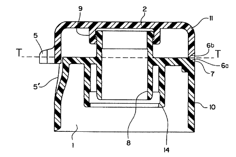
FIG. 5 shows a vertical section taken through the
snap-on plastic hinged closure along the line X-X as shown
in FIG. 3. The pouring spout 8, surrounded by a concentric
outer wall 14, which can be clamped on <~ container neck,
can also be seen in FIG. 5. An annular wall 9 which
sealingly extends around the spout 8 is disposed on the
8
CA 02135379 2001-07-30
inner surface of the lid 2. The compression-resistant flip
element 7 can be seen, and it can also :be clearly seen that
the pivot axes 6a, 6b extend symmetrically in relation to a
plane of separation T, indicated by a dashed line. It can
further be seen that the pivot axes 6a, 6b are disposed
within the jacket walls and thus form a non-protruding
hinge, for the first time in this type of snap closures.
The jacket wall of the lower part 1 is .indicated by element
reference numeral 10, the jacket wall o:f the lid 2 by
element reference numeral 11.
The particularly important joint o:f this invention is
shown in FIG. 6 in an enlarged scale. The situation of the
completely opened closure is illustrated in FIG. 6. It can
be clearly seen that in a sectional view the flip element 7
has the general shape of an isosceles triangle. In the
preferred embodiment shown in FIG. 6, the triangle is a
right-angled isosceles triangle. Accordingly, the flip
element 7 is bounded on both sides by the thin areas 12a,
12b, which define the pivot axes 6a, 6b,, respectively.
This roof-shaped compression-resistant flip element 7 thus
forms a support surface 15a on one side and a support
surface 15b on another side of the compression-resistant
flip element 7. In the closed state of the closure, the
one support surface 15a comes to rest on an inclined
opposite surface 16 on the lower part 1~:, and the other
support surface 15b comes to rest on an inclined opposite
surface 17 on the lid 2. The opening angle between the
9
CA 02135379 2001-07-30
support surface 15a and the opposite surface 16 on the
lower part 1I, as well as between the oppositely located
support surface 15b and the opposite surface 17 on the lid
2 is respectively 90°. This permits the division of the
pivot movement of the lid 2 with respect to the lower part
1 into respectively two pivot movements of respectively
90°.
Basically, it is possible for the angle between the
two support surfaces 15a and 15b to be less than 90°,
however, this requires that the opposite surfaces 16 and 17
be designed somewhat flatter. The smaller the angle
between the two support surfaces 15a and 15b, the more the
flip element 7 would project into the closure. But since
the portion of the support surfaces 15a and 15b projecting
past the opposite surface 16 or 17 is ineffective, the
triangular portion of the flip element '7 can be truncated,
as illustrated in FIG. 7. This results in a flip element 7
which in cross section has the general ahape of an
isosceles trapezoid. Approximate right angles a,a which
are to be maintained between the supporl~ surfaces 15a and
15b. and the opposite surfaces 16 or 17 <~re also indicated
in FIG. 7.
It is possible to apply two different angles, which
would complement each other to form 180", in place of the
two right angles. But such embodiment results in an
inclination of the flip element 7 in the completely closed
CA 02135379 2001-07-30
position of the closure. This may be desirable in
exceptional cases for specially designed closures.
It can also be seen in FIGS. 6 and 7 that the thin
areas 12a and 12b forming the pivot axes 6a, 6b are
situated inside of the jacket walls 10 or 11 of the lower
part 1 or the lid 2.
When closing the closure of this invention, the lid 2
together with the flip element 7 is first pivoted around a
pivot axis 6a between the support surface 15a and the
opposite surface 16 on the lower part 1 until these two
surfaces come to rest on each other, after which during
pivoting over a further 90° the pivot movement around the
second pivot axis 6b between the support surface l5b and
the opposite surface 17 on the lid 2 takes place. These
two pivot movements take place in a reversed manner during
opening.
If now the spring characteristics of conventional
snap-on hinged closures and of the snap-on hinged closures
of this invention are compared, the corresponding
characteristic lines in FIGS. 8 and 9 result. FIG. 8 shows
a conventional snap-on hinged closure with a joint having
only one pivot axis 6, and it can be seen that in the area
of dead center a maximal shape change o:~ Dl occurs, while
the snap-on hinged closure in accordance with this
invention with two pivot axes 6a, 6b considerably reduces
the maximal shape change. This results in a longer,
relatively large pivot force over the entire pivot movement
11
i
CA 02135379 2001-07-30
of the lid without, however, causing a deformation of such
a size as with the uniaxial design of the joint. By means
of this the complete opening of the lid over 180° is also
assured. Up to now this has been only a desirable idea
which, however, was never accomplished. Furthermore, by
means of these graphics it is possible to explain that a
considerably reduced maximum load is placed on the joint or
the two pivot axes 6a, 6b, which results in a reduction of
the formation of cracks and scores. Stretching or white
fractures, which can be clearly seen by the naked eye when
they occur in snap-on hinged closures i:n accordance with
the state of the art, can hardly be detected in the
closures of this invention.
12