Note: Descriptions are shown in the official language in which they were submitted.
WO 93/24085 2 1 3 6 0 6 ~ PCI/US93/04036
DISPC)SABLE TRIUNING PAM HAVING
IMPROVED ~ I Ht I CHABLE SIDE PANFL
FELD OF THE INVENrlON
The present invention related to dispos~hle absorbent articles, more
particularly to ~ po~hle a~sorbent diapers and incontinent products, and most
particularly to disposable ~raining pants and pull-on diaper. The invention is
directed panicularly to such articles and products. especi~lly training pants. which
have an el~etici~e~ side panel that p-u~/ides the training pant with improved fit ana
comfort. As used herein, ~l-air,ing pant~ includes also pull-on diapers comprising
an absorbent core.
DESCRIPTION OF REIA I tv ART
Training pants have become popular. esreo~ y for use on toilet training
children. In the past some training pants have t~een made elas'~ y extensiLle using
elastic elements l~isposed in the training pants such that the waist opening and leg
openings are at least panially enc;.clad with e~l;c;~ed bands. This method of using
elastic ele.l,en~s is shown in U.S. Patents 4.205,679 to Repke, et al.; 4.610,680 to
LaFleur; 4.610,681 to Slrohbeen. et al.; 4;641,381 to Heran, et al.; 4,909,804 to
~5 Douglas, Sr.; and 4.960.414 to Meyer.
Another method of el~stic;~;ng d;~ .os~le training pants is shown in U.S. Patents
4.490.464; 4.g38,753; and 4.938.757 all of which issued to Van Gompel, et al.
These patents ~isclose a pant-like garment formed by attaching discrete stretchable
IllelllLer~ to the side edges of the main body of the garment. The discrete stretchable
",e"lt~er~ are des~,iLe~ as being made by sl,e~Lt,ing an elastic or sllelcl,able layer to
a selected elongation, placing a nonslletchable layer, such as a nonwoven, on the
slretched layer, bonding the layers together, and ~'lu; ing the layers to relax so that
the nonst,~tcl,able layer is gathered.
Other methods for making a stretchable member is described in U.S Patent
4.107.364, issued to Sisson on August 15, 1978, U.S. Patent 4,209.563 issued to
Sisson on June 24. 1980. U.S. Patent 4.525.407 issued to Ness on June 25. 1985.
U.S. Patent 4.834,741 issued to Sabee on may 30. 1 989. European Patent
273~67
Publication 409,315. The Procter & Gamble Company, published January 23,
1991.
Still other methods for making a stretchable member is described in
United States Patents numbered 5,167,897 (issued December 1, 1992);
5,156,793, issued October 20, 1992; and 5,143,679, issued September 1, 1992
and assigned to The Procter & Gamble Company. These patents describe
making an elasticized laminate by mechanically stretching a zero-strain
stretch laminate web to impart the elasticity thereto in the direction of
stretching, at least up to the point of initial stretching. An elongatable, non-elastic nonwoven layer is first bonded to a liquid-impervious elastic layer
while in its relaxed state to form the laminate web. The laminate web is then
fed between a pair of opposed pressure applicators, preferably ones having
three-dimensional surfaces which are complimentary to a varying degree
with one another, and subjected to incremental mechanical stretching (or
nonuniform or sequential mechanical stretching, as desired), whereby the
elongatable nonwoven is permanently elongated in the direction of
stretching. When the mechanical stretching is removed, the elastic layer will
enable the laminate to return substantially to its pre-stretch shape and
dimensions, thereby rendering the non-elasticized laminate elastically
extensible in the direction of initial stretching.
While the elasticized zero-strain stretch laminates described above are
useful for making elasticized, stretchable side panels for training pants, they
are not completely satisfactory. The elongatable non-elastic nonwoven layer
of the laminate can be torn at least partially along lines oriented in the
machine direction of the web, and perpendicular to the direction of stretch.
The at least partial tearing of the nonwoven can diminish the contribution of
the nonwoven to the tensile strength of the laminate. Furthermore, the elastic
layer itself generally has low tensile strength and low tear propagation
resistance. This property can be problematic when the elasticized laminate is
used as a side stretch panel on a training pant to achieve stretch in the lateral
(front-to-back) direction of the training pant while being worn, since the linesof at least partial tearing of the nonwoven of the laminate are then oriented in
2a
2 ~ 3~7 ~
the longitudinal (machine) direction. Further, since the side seam is most
preferably made in the longitudinal (machine) direction of the training pant
(in order to optimize manufacturing speed and efficiency), the side seam can
partially tear prematurely (for example, while the child is active) along the
5 seam where the process for forming the side seam itself can further damage
to some extent either the nonwoven or the elastic layer of the laminate, or
both, along one or more of the lines of at least partial tearing of the
nonwoven.
3 a 1 3 ~
SUMMARY OF THE INVENTION
Though the problem may be solved by various means, none are
completely satisfactory. For example, additional materials could be added to
or between the front and the back edge portions of the side panels to make
the seam stronger and to reduce damage to the elastic layer. However, the
inventors have found that the problem can be solved by modifying the
method for making the elasticized laminate used to form the elasticized side
panels. During the making of the elasticized laminate, discrete and spaced
apart regions of the laminate which is fed between the opposed pressure
applicators are subjected to no or reduced mechanical stretching. After the
laminate has been mechanically stretched, it is cut along its width (in the
direction of feeding) in the middle of the regions where no or reduced
mechanical stretching occurred (hereinafter referred to as "non-stretched
region"). The widths of laminate are then cut to the appropriate lengths for
front and back elasticized members. The non-stretched region is used as the
respective outboard edge portions of the front and back elasticized members
which are then joined to form the side seam. Thus, the present invention
provides a side seam that has substantially improved strength and tear
resistance, and provides a training pant with elasticized side panels having
improved side seam integrity.
Another aspect of this invention is as follows:
A disposable training pant comprising:
1) an absorbent chassis having side edges and a front and a back
waist area, comprising:
a liquid-pervious topsheet,
a liquid-impervious backsheet, and
an absorbent core positioned between said topsheet and said
backsheet; and
2) an elasticized side panel attached to and joining the front waist
area and the back waist area along each longitudinal side of the absorbent
chassis, said side panel being laterally stretchable, comprising:
a front elasticized member and a back elasticized member, each
6~67 ~
comprising:
(i) an outboard edge portion comprising a non-elasticized
laminate material comprising at least one nonwoven layer
and at least one elastic layer, and
(ii) an elasticized laminate portion; and
a side seam joining said outboard edge portions of said front
elasticized member and said back elasticized member.
BRIEF DESCRIPTION OF THE DRAWINGS
Fig. 1 is a schematic view of a training pant according to the present
invention.
Fig. 2 is an explanatory view showing an apparatus for preventing
contraction of a web used in the present invention.
Fig. 3 is an explanatory view showing the matching condition of upper
corrugated rolls 60 and lower corrugated rolls 61 in the apparatus shown in
Fig. 2.
Fig. 4 is an explanatory view showing how the web is cut into two
elasticized members with an angle.
Fig. 5 is an explanatory view showing how the seal is attached to the
elasticized members with an angle.
Fig. 6 is an explanatory view showing how the elasticized member is
attached between the backsheet and the cuff.
DETAILED DESCRIPTION OF THE INVENTION
Practice of the present invention involves the making of a training pant
I (Figure 1) comprising the steps of: making of the elasticized members
having a non-mechanically stretched outboard edge portion, making of the
absorbent chassis, attaching the elasticized members to the edges of the
absorbent chassis, and forming
WO 93/24085 -Z 1 ;~ 6 ~ 6 7 PCI'/US93/04036
the side seam between the non-elasticized outboard edge portions of the elastici~ed
members to form the training pant with elasticized side panels.
The el~stici~ed members are generally made by: laminating into a laminate web
at least one elongatable, non-elastic nonwoven layer with a elastic layer while in its
relaxed state; mechanically stretching portions along the width of the laminate web
to impart elasticity thereto in the direction of stretching. at least up to the point of
initial stretching, thereby leaving other regions of non-elasticize~ stretched
laminate; and cutting the resultant elasticized laminate web along its width and its
length to form the individual front waist area and back waist area elasticized
members of the side panel.
The absorbent chassis is generally made by placing an absorbent core between a
liquid-impervious backsheet and a liquid-pervious topsheet. The absoroent chassis
of the present invention is generally of a rectangular shape. having side eages and end
edges, and a front and a back waist area.
The el~clic-;~ed members are then attached along the side edges in the front waist
area and the back waist area of the chassis. so that a portion of the non-mechanically
stretched region of the ela~lic;~ed ",e",~er is the outboard edge portion thereof.
Finally, the abso,L.en~ chassis with the el~(;o;~ed members attached is folded at
approximately the longitudinal center. bringing the body-side face (topsheet face) of
the front waist area into proximity with the body-side face of the back waist area
The body side surfaces of the non-mechanically stretched edge pollions of the opposed
el~tici~ed members allached to the front and back waist areas are then joined with a
heat seal, thereby completing the training pant.
An el~ctici,P~ member 10 is generally made by: laminating into a laminate web
11 at least one elongatable, non-elastic nonwoven layer 12 with at least one elastic
layer 13 while both are in their relaxed state; mechanically stretching portionsalong the width of the laminate web 11 to impart elasticity thereto in the direction of
stretching, at least up to the point of initial stretching, thereby leavlng other
regions of non-elastici7ed laminate; and cutting the resultant stretch laminate web
14 along its width and along its length, to form the individual front waist area and
back el~cli~;~ed members 10 of the side panel 5.
A typical example of the elongatable, non-elastic nonwoven layer 12 comprises
a hyd,ophobic, nonwoven carded web having a basis weight in the range of about 30
37 grams per square meter and comprised of approximately 1-5 denier fibers
available from Hercules, Inc.. U.S.A.
The elastic layer 13 can be liquid pervious or liquid impervious, such as with asDunbonded polymeric nonwoven or a Dlastic film. A typical examDIe of the elastiC
layer 13 comprises a po~yurethane having a no-load caliper or thickness of
WO 93/24085 2 1 3 6 0 6 7 PCI/US93/04036
-
approximately 0.045 mm (2 mil). An examDIe includes DS-320C made by .,a3an
Synlhetic Rubber K.K.
The non-elastic nonwoven layer and the elastic layer are brought together and
bonded to form the laminate 11. The adhesive to bond the layers can be applied as a
5 uniform continuous layer of adhesive. a patterned layer of adhesive or an array of
separate lines spirals or spots of adhesive. In a preferred embodiment. the
adhesive selected is stretchable and the glue applicator comprises a melt blown
application system such as Model No. GM-50-2-1-GH available from J~M
Laboratories of Gainesville Georgia. U.S.A. employing a nozzle having 8 orifices per
linear centimeter (20 orifices per linear inch) as measured in the-cross-machinedirection each orifice measuring about 0.~ mm (0.020 inches) in diameter. A
preferred adhesive is HM-6~15 Hot Melt Adhesive available from H. B. Fuller
Company of S~. Paul Minnesota U.S.A. The adhesive is heated to a temperature of
about 170 degrees cer,ligrade and applied at a rate of about 0.75-1.25 milligrams
l 5 per square centimeter. Heated co-"~,r~:ssed air at a te~peralure of about 220 degrees
cenlig,ade and a pressure of about 2500 mm Hg gauge is issued through the
secondary orifices in the nozzle to assist in uniform distribution of the adhesive
fibrils during the laydown operation.
As generally shown in Figure 2 the laminate 11 web is then mechanically
stretched to provide along the width of the web regions 15 of elasticized laminate and
regions 20 of non-stretched non-elasticized laminate. Typically a web of
approximately 1 meter in width W is fed through the sl,etching apparatus at a time.
An apparatus for mechanical st,etching the zero-strain stretch laminate 11 can
consist of upper corrugated rolls 60 and lower corrugated rolls 61 which are
matched so that the respecli-/e corrugations can mesh (as further shown in Figure
3). The region 15 of the web which has passed through and between the upper and
lower corrugated rolls is mechanically stretched in the areas between the grooves 62
of the upper corrugated roll 60 and the grooves 63 of the lower corrugated roll 61.
The regions 20 of the web which has passed between side-by-side upper corrugated rolls 60 do not receive any mechanical 5t,etching.
It is preferred to use a means of clamping the web iust outside the respective
regions of mechanical stretching in order to prevent the web from contracting in a
direction parallel to the direction of stretching as the web passes between the meshed
rolls. A suitable means of preventing such contraction is shown in Figure 2. where
compressible disks 6~ having a slightly larger diameter than the diameter of theupper corrugated rolls 60 are mounted adjacenl each side of the grooves portions of
the upper corrugated rolls. The compressible disks tightly grip the web and hold it
W O 93/24085 2 1 3 6 0 6 7 PC~r/US93/04036
securely against the coinc;Jing non-grooved portions 64 of the lower corrugated roll
61.
In the present invention, the regions 15 of mechanical stretching and the
regions 20 of non-sl~el~ g will alternate along the width of the web. The width of
the region 15 to be mechanically stretched ~shown as X) is selected based on thedesired waist opening of the training pant and the degree of elasticity of the stretch
laminate, as well as on how the processed web 14 is cut after stretching into the
individual side elaslic;~ed members 10. For example. the processed web 14 can becut, such as with knives, along its width a~ approximately the center of each of the
regions 20 of non-mechanical stretching. Then as shown in Figure 4. each
individual width of ,~rucesse~ laminate can further be cut into half substantially in
the center of the region of mechanical stl~tching. and cut into individual lengths L
along the length of the web, to form sets of first side 10a and second side 10b
el~ct;c;~d members for allac~""ent to the absorbent chassis and forming of the side
seam. Depending on the size of the training pant to be made, the width X can be from
60-140 mm. For example, for a Large training pant intended for use by a child
weighing from about ~-14 kg, the width X is about 70-100 mm, more preferably
from 74-80 mm. In a particularly p,eferred e",bodi",ent. the width X is about 78mm. Thus, after having cut the individual lengths of web in about the center of the
region X, the width of the el~stici~ed laminate portion 16 of an individual sideelasticized member of this embodiment will be from about 30-70 mm. For the
aforementioned Large training pant, the width X is from about 35-50 mm, more
preferably from 37-40 mm, and particularly a~out 39 mm.
Preferably, the width of a region 20 of non-r~er:hanical stretching of the web
'5 (shown as Y) will be from aboùt 20-120 m~ he aforementioned Large
training pant, the width Y is about 20-60 mm, more preferably from 40-56 mm,
and particularly about 50 mm. Since the web is cut in the center of the region Y in
making the individual widths of web, the width of the non-mechanically stretchedoutboard edge portion 51 of the el~ctici~ed member is about 10-60 mm, and for the
aforementioned Large training pant, Y is about 10-30 mm, more preferably from
20-28 mm, and particularly about 25 mm.
P~eler~ble the length L of each elasticized member is from about 50-190 mm.
As with the other dimensions of the elasticized members, the length L selected will
depend on the size of the intended wearer, and fit and comfort considerations. For the
aforementioned Large training pant, the length L is from about 80-170, more
preferably from about 100-160 mm.
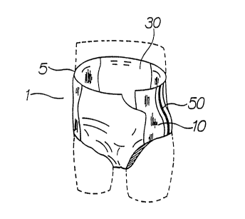
The absorbent chassis 30 is generally made by Dlacing an absorbent core 31
between a liquid-impervious backsheet 32 and a liquid-Pervious topsheet 33. The
W O 93/24085 P(~r/US93/04036
7 21360~7
absorbent chassis of the present invention is generally of a rectangular shape.
having side edges 35a.35b and end edges 36a.36b. and a front waist area 40 and aback waist area 41.
The absorbent core 31 can be any absorbent means which is generally
compressible, conformable, non-irritating to the wearer's skin, and capable of
absGrbi"g and retaining liquids such as urine and other certain body exudates. The
absorbent core has a garment surface. a body surface. side edges, and waist edges.
The absGr~en~ core may be manufactured in a wide variety of sizes and shapes (e.g.,
rectangular, hourglass, ~r-shaped. asymmetric. etc.) and from a wide variety of
liquid-absGrL,ent materials commonly used in dispos~hle diapers and other absorbent
articles such as comminuted wood pulp which is generally referred to as airfelt.Examples of other suitable absorbent materials include creped cellulose wadding,meltblown polymers including cross-linked cellulosic fibers. tissue including tissue
wraps and tissue laminates, absorbent foams, absorbent sponges, superabsorbent
polymers, absG,Lent gelling materials. or any equivalent material or combinations
of materials. The configuration and construction of the absorLent core may also be
varied (e.g., the absor~ent core may have varying caliper zones, a hydrophilic
gradient, a su~erabsc,r~ent gradient. or lower average density and lower averagebasis weight ~cql~isition zones; or may cG-"prise one or more layers or structures).
The total aLso,L.ent capacity of the absorbent core should, however, be compatible
with the design loading and the intended use of the diaper. Further, the size and
absGrt,enl capacity of the absorbent core may be varied to accommodate wearers
~angi"g from infants through adults.
In one e",~odi."ent of the present invention, the absorbent core 31 comprises
~5 two distinct webs or layers comprising an ~cquisition/distribution core and a storage
core (neither shown). The acquisition/distribution core is positioned between the
topsheet and the storage core, and the storage core is positioned between the
acquisition/distribution core and the backsheet. The acquisition/distribution core
has a top surface area which preferably is from 15% - 170% of the top surface area
of the storage core. The acquisition/ distribution core is preferably positionedrelative to the storage core so that none of its surface area extends beyond the~ boundaries of the storage core. The acquisition/distribution core preferably
CG"~ ises a web of chemically stiffened cellulosic fibers, although binding means
such as non-stiffened cellulosic fibers, synthetic fibers, chemical additives. and
thermopl~stic fibers can be added to increase the physical integrity of the web. The
storage core preferably comprises an airlaid web of superabsorbent material and
fiber material, preferably airfelt. Optionally. and most preferably, a pervious
sheet (e.g., a tissue sheet) or other scrim may be positioned between the
8 2 ~ 7
._
acquisition/distribution core and the storage core to increase the integrity of
the absorbent core during processing and/or use.
The acquisition/distribution core serves to quickly collect discharged
body fluids, to quickly transport the fluid from the point of initial contact to5 other parts of the acquisition/distribution core, and to temporarily hold suchdischarged body fluids until they can be absorbed by the storage core. The
distribution function of the acquisition/distribution core is of particular
importance in order to more fully utilize the capacity of the storage core.
Thus, while the acquisition/distribution core may comprise a wide variety of
10 absorbent materials, it preferably comprises fiber material that can rapidly
transport fluid and not collapse upon being wetted so that the
acquisition/distribution core can effectively acquire and distribute second
and successive voids of fluid as well as utilize a minimal amount (<2%) of
superabsorbent material (due to the slowness of their uptake and gel
15 blocking).
The backsheet 32 is impervious to liquids (e.g., urine) and is preferably
manufactured from a thin plastic film, although other flexible liquid
impervious materials may also be used. As used herein, the term "flexible"
refers to materials which are compliant and will readily conform to the
20 general shape and contours of the human body. The backsheet prevents the
exudates absorbed and contained in the absorbent core from wetting articles
which contact the diaper such as bedsheets and undergarments. The
backsheet may thus comprise a woven or nonwoven material, polymeric
films such as thermoplastic films of polyethylene or polypropylene, or
25 composite materials such as a film-coated nonwoven material. Preferably,
the backsheet is a thermoplastic film having a thickness of from about 0.012
mm (0.5 mil) to about 0.051 mm (2.0 mils).
The backsheet 32 is positioned adjacent the garment surface of the
absorbent core and is preferably joined thereto by attachment means such as
30 those well known in the art. For example, the backsheet may be secured to
the absorbent core by a uniform continuous layer of adhesive, a patterned
layer of adhesive, or an array of separate lines, spirals, or spots of adhesive.
8a
Adhesives which have been found to be satisfactory are manufactured by
Century Adhesives, Inc. of Columbus, Ohio and marketed as Century 5227;
and by H. B. Fuller Company of St. Paul, Minnesota and marketed as HL-
1258. The attachment means will preferably comprise an open pattern
network of filaments of adhesive as is disclosed in U.S. Patent 4,573,986
entitled "Disposable Waste-Containment Garment", which issued to Minetola
and Tucker on March 4, 1986. An exemplary attachment means of an open
pattern network of filaments comprises several lines of adhesive filaments
swirled into a spiral pattern such as is illustrated by the apparatus and
methods shown in U.S. Patent 3,911,173 issued to
2 ~ 7 *
b7_
Sprague, Jr. on October 7, 1975; U.S. Patent 4,785,996 issued to Ziecker, et al.on November 22, 1978; and U.S. Patent 4,842,666 issued to Werenicz on June
27, 1989. Alternatively, the attachment means may comprise heat bonds,
pressure bonds, ultrasonic bonds, dynamic mechanical bonds, or any other
- 5 suitable attachment means or combinations of these attachment means as are
known in the art.
The topsheet 33 is compliant, soft feeling, and non-irritating to the
wearer's skin. Further, the topsheet 33 is liquid pervious permitting liquids
(e.g., urine) to readily penetrate through its thickness. A suitable topsheet
can be manufactured from a wide range of materials, such as porous foams;
reticulated foams; apertured plastic films; or woven or nonwoven webs of
natural fibers (e.g., wood or cotton fibers), synthetic fibers (e.g., polyester or
polypropylene fibers), or a combination of natural and synthetic fibers.
Preferably, the topsheet is made of a hydrophilic or a surfactant-treated
hydrophobic material.
The topsheet 33 is positioned adjacent the body surface of the
absorbent core and is preferably joined thereto and to the backsheet 32 by
attachment means (not shown) such as those well known in the art. Suitable
attachment means are described with respect to joining the backsheet to the
absorbent core. As used herein, the term "joined" encompasses
configurations whereby an element is directly secured to the other element by
affixing the element directly to the other element, and configurations
whereby the element is indirectly secured to the other element by amxing the
element to intermediate member(s) which in turn are affixed to the other
element. In a preferred embodiment of the present invention, the topsheet
and the backsheet are joined directly to each other in the diaper periphery
and are indirectly joined together by directly joining them to the absorbent
core by the attachment means.
The elasticized members 10 are then attached to the front waist area 40
and the back waist area 41 on each side edge 35a.35b of the chassis, so that thenon-mechanically stretched outboard edge portion 51 thereof is the distal
edge. The inboard attachment edge 17 of the elasticized member 10 is
7 C
preferably attached to the absorbent chassis 30 between the topsheet 33 and
the backsheet 32 by means of an adhesive 18 applied to either surface,
preferably both surfaces, of the inboard attachment edge 17. The inboard
attachment edge 17 of the elasticized member can alternatively be attached
5 between the backsheet and other structures or layers of material in the
chassis; for example, as shown in Figure 6, between the backsheet and an
inboard elasticized barrier leg cuff 55. Generally, the width of the attachment
edge 17 inserted and attached between the topsheet and backsheet if from
about 5-20 mm, more preferably from about 10-15 mm. The adhesive can be
i~
W O 93/24085 2 1 3 6 0 ~ 7 PC~r/US93/04036
applied in any effective means, such as continuously, in1ermiltently, in either a
straight or curved line, or in a swirl pattern.
Finally, the absor~ent chassis 30 with the el~clic;~ed members 10 attached is
mechanically folded at approximately the longitudinal center 42, thereby bringing
the body-side face 34 of the front waist area 40 into proximity with the body-side
face of the back wais~ area 41. The body-side facing surfaces of the outboard edge
portions 51 of the opposed elasticized members 10 attached to the front and backwaist areas are then joined with a seal 52, thereby forming an el~stici~Pd side panel
5 and completing the training pant. The seal 52 can be made parallel with the
longitudinal side ~5 of the absorbent chassis. or can be angled slightly, as shown in
Figure 5. The seal 52 is preferably made as thin as possi~'e to minimize the width
of the side seam 50 formed. A prefer,ed seal is a pressure bond seal which bondstogether the e~astic layers 13 of the respecting outboard edge portions 51 of the
laminates. In a pfelelled method, the seal 52 is made by passing the outboard edge
pGrtions between a rotating anvil roll and a rotating pressure roll which typically
exert about 1500-5000 k~3ra",s force per square centimeter pressure on the
laminae, thereby forming a line of seal 52 having a width generally from 1-10 mm,
pf~ferably from 2-5 mm. The bonding pattern can be continuous or inter",ittent,
and straight, curved, or irregular. Preferably, a temperature below about 80
degrees cenliy,ade is used. It is most preferred to operate the anvil and the
pressure roll at their ambient temperature. A higher temperature can be used so
long as it is well below the thellllgpl~clic melting temperature of the material of the
elastic layer and so long as the elastic layer itself is not da",aged or weakened at such
temperatures. Thus, the pressure. temperature. bond pattern and duration of
application of the sealing means is selected to optimize the welding of the polymeric
materials of the respective el~ctici~ed layer of the laminates without deteriorating
the laminate or its components. The side seam 50 can also be made by other sealing
means known in the art, including ultrasonic sealing, heat sealing, and combinations
thereof.
After the side seam 50 is made, the excess material outside of the seal can be
trim cut away along a line 53 outboard ot the seal 52. Further, po,lions of the side
panels can be trim cut, particularly around the leg opening edge, to provide an
improved fit and better comfort. The elasticized members 10 can be trim cut
together immediately before or after seaming, or the front and back elasticized
members can be trimmed separately prior to or after attachment to the absorbent
chassis.
Optionally, the training pant of the present invention can comprise other
features and structures commonly used in diapers and training pants. Such optional
WO 93/24085 ' PCI'/US93/04036
21360~7
features include but are not limited to: disposa~ tapes. elAcli.-;~ed waist and tummy
panels in the back and front waist areas of the absorbent chassis; el~slic;ced outboard
leg cuffs and el~stici~ed inboard barrier leg cuffs. positioned generally along the
sides of the absGrLenl chassis to partially surround and seal around the leg ~peni"g of
S the training pant; wetness indicators; and elasticized ",e"lbe,~ in the crotch region
of the al~sGr~enl chassis to provide better cG",f~rl. fit and containment of bodily
~Yu~t~s
The effect of the present invention is to provide a training pant having
el4sl~ ed side panels which have an improved side seam therein. The seam such asone formed by a pressure sealing, is strong enough to remain sealed under ordinary
use yet can be easily tom by a peKon ~esi,ing to remove the training pant from the
wearer for example after the pant has been soiled.