Note: Descriptions are shown in the official language in which they were submitted.
104050-2CA
-1-
WINDOW SCREEN APPARATUS
FIELD OF THE INVENTION
This invention relates generally to window screen
assemblies.
BACKGROUND OF THE INVENTION
A window screen consists of mesh, or screening, supported
by a lightweight rectangular frame. The frame includes four
essentially straight segments, i.e., the top, the bottom, and
the left and right sides, which are connected at adjacent ends
yo to form the corners of the frame. The ends of the segments are
either cut at forty-five degree angles and connected directly
together to form ninety-degree corners, or the ends are cut to
mate with "corner keys,~~ which are corner-shaped connectors.
Each corner key basically consists of two legs with their
~s adjacent ends joined at a ninety degree angle to form a corner.
The free ends of the legs fit within or over the adjacent ends
of the frame segments, to connect these segments via the
corner, at a ninety-degree angle.
The screen frame slides either vertically or horizontally
so along tracks on the outer edges of the window jambs. The
screen does not fit tightly in the tracks, since the screen
will ordinarily require replacing several times before the
window requires replacing. Accordingly, the screen must be
able to be readily removed from and installed in the tracks.
zs In prior known window screen assemblies the screen frames
include on at least one side a segment stop, in the form of a
narrow ridge. This ridge prevents the screen from penetrating
too deeply into the track. Each ridge, which is offset from
the outer edge of the segment, runs parallel to the edge, and
so extends the entire length of the segment. It thus essentially
widens the segment, so that only the portion of the segment
that is to the outside of the ridge rides within the track.
104050-2CA
-2-
The screen can then be shifted and removed, or withdrawn, from
the tracks.
The frames must be lightweight and low cost to be
competitively marketed. Including these segment-long ridges on
s the frame segments increases the weight of the segments and the
amount of raw material used to make them. To minimize the
weight and the materials used, the ridges must be quite narrow.
However, manufacturing segments with these narrow -ridges
requires custom designed, and thus, expensive machinery, which
io adds to the cost of manufacture.
After the frame segments are manufactured, they are
assembled to form the frame. Then, handles used to move the
screen along the tracks are attached, either to the side or
bottom segments of the frame. This assembly process is labor
~s intensive, which adds to the cost of the frame. Further, holes
for screws or other cut-outs for attaching the handles to the
frames must be included on the frame segments, which
complicates the manufacturing process. Alternatively, the
handles may be incorporated into an extruded frame segment,
2o which adds to the cost of producing the segment, and thus, the
cost of the frame.
What is needed is a window screen frame that is simpler
and less expensive to manufacture than the prior, known frames.
zs SUMMARY OF THE IN~IENTION
The invention is an improved window screen frame that
includes at least one corner key with an integral stop. The
two legs of the corner key support raised members that extend
approximately half the length of the legs and are spaced from
so and run parallel to the outer edges of the legs. Preferably,
members meet where the legs join, to form a corner-shaped stop.
The stop is relatively small, and does not add much weight
to the frame. Accordingly, it need not be as narrow as the
segment-long ridges of prior systems. The stop is readily
ss incorporated into the corner key, which is preferably molded
plastic, and thus, one-piece and easy to manufacture. These
corner-shaped stops replace the segment-long ridges used in
64421-567
3
prior frames. The frame segments currently used are thus
easier and less expensive to manufacture than the prior
segments.
In an alternative embodiment, one or more of the
corner keys also includes an integral handle, which is
molded into the inside edge of the corner key. These corner
keys eliminate the separate handles of prior assemblies.
Accordingly, they significantly reduce the time required to
assemble a frame, and thus, the associated costs. They are
also easier and less expensive to manufacture than extruded
frame segments with integral handles. These corner keys may
be installed on two of the four corners, depending on
whether the screen moves vertically or horizontally.
In a second alternative embodiment, one or more of
the corner keys also includes retreats for pins used to lock
the screen against movement. The pins extend from the
interior, through the window frame and into the retreats.
Once the pins are in place in the retreats, the screen can
not be moved, and thus, cannot be removed from the tracks.
The retreats are readily incorporated into the corner keys.
In prior systems, the retreats must be cut into the frame
segments, which complicates their manufacture. A corner key
constructed in accordance with this embodiment may include a
stop, a handle or both.
The invention may be summarized according to one
aspect as a window screen frame for supporting screening,
the frame adapted to ride within tracks of a window jamb
said window screen frame including: A. four frame segments
forming a top, a bottom, a first side and a second side of
the frame; B. corner keys interconnecting the frame segments
A
64421-567
213
3a
and forming frame corners, at least one of the corner keys
including a raised stop having first and second opposing
side surfaces connected by an outer frame surface, the stop
being positioned a predetermined distance from an outer edge
of the key and substantially parallel to the track in which
the frame moves, wherein one of said opposing sides of the
stop prevents the frame from penetrating beyond the
predetermined distance into the tracks.
According to another aspect the invention provides
a window assembly for use with a window frame having tracks
within which a window screen moves, the window assembly
further including: A. a locking mechanism for preventing the
screen from moving within the track, the locking mechanism
including a plurality of pins adapted to extend through the
window frame and engage the screen; B. a window screen
having a frame with i. four frame segments forming a top, a
bottom, a first side and a second side of the frame; ii.
corner keys for interconnecting the frame segments and
forming frame corners, at least one of the corner keys
including a raised stop having first and second opposing
side surfaces connected by an outer frame surface, the stop
being positioned a predetermined distance from an outer edge
of the key and substantially parallel to the track in which
the frame moves, wherein one of said opposing sides of the
stop prevents the frame from penetrating beyond the
predetermined distance into the tracks, one or more of the
corner keys further including one or more retreats for
receiving one or more of the pins.
According to yet another aspect the invention
provides a window assembly for use with a window frame
having tracks within which a window screen moves, the window
A
64421-567
3b
assembly further including: A. a window screen having a
frame with i. four frame segments forming a top, a bottom, a
first side and a second side of the frame; ii. corner keys
for interconnecting the frame segments and forming frame
corners, at least one of the corner keys including a raised
stop, which is positioned a predetermined distance from an
outer edge of the key, for preventing the frame from
penetrating beyond the predetermined distance into the
tracks, one or more of the corner keys further including one
or more retreats for receiving one or more pins; and B. a
locking mechanism for preventing the screen from moving
within the tracks, the locking mechanism including i. a
plurality of pins that extend through the window frame and
engage the window screen, each pin including on one end a
protrusion, and ii. for each pin a housing supported by the
window frame, each housing being shaped to receive the end
of the pin with the protrusion and hold the end by friction,
to prevent the pin from engaging the retreat.
According to still another aspect the invention
provides a corner key for use in a window assembly to join
frame segments to form a frame, the corner key including: A.
a first leg with a first end and a second end, the second
end supporting a first raised member having first and second
opposing side surfaces connected by an outer frame surface,
the member being positioned a predetermined distance from an
outer edge of the key and substantially parallel to the
outer edge; and B. a second leg with a first end and a
second end, the second end supporting a second raised member
having first and second opposing side surfaces connected by
an outer frame surface, the member being positioned the
predetermined distance from the outer edge of the key and
substantially parallel to the outer edge, the second ends of
64421-567
3c
the legs meeting at an angle to form a corner section with
the raised members at an angle relative to one another to
form a stop, wherein the first ends of the legs slideably
engage two frame segments and connect the segments, via the
corner section formed by the second ends, with the stop
raised outwardly from the corner section wherein, when the
corner key is included in an assembled frame, one of the
opposing sides of one of the raised members prevents the
frame from penetrating beyond the predetermined distance
into a track in the window assembly.
According to a final aspect the invention provides
a corner key for use in a window assembly to join frame
segments to form a frame, the corner key including first and
second legs that each include an upper portion and a lower
portion: A. the upper portion of the first leg supporting a
first raised member which is positioned a predetermined
distance from an outer edge of the key; and B. the upper
portion of the second leg supporting a second raised member
which is positioned the predetermined distance from the
outer edge of the key, C. the lower portions of the legs
engaging the frame segments, the lower portions having U-
shaped cross-sections and including inwardly pointing tabs
that retain the legs within the frame segments into which
the legs are inserted, the legs meeting at an angle with the
upper portions forming a corner section and the raised
members meeting at an angle relative to one another form a
corner-shaped stop that extends outwardly from the corner
section, wherein the lower portions of the legs slideably
attach to two frame segments and connect the segments, via
the corner section, at an angle.
A
64421-567
3d
BRIEF DESCRIPTION OF THE DRAWINGS
The above and further advantages of the invention
may be better understood by referring to the following
description in conjunction with the accompanying drawings,
in which:
Fig. 1 depicts a window screen frame constructed
in accordance with a first embodiment of the invention;
Fig. 2 depicts in more detail a corner key
utilized in the frame of Fig. 1;
Fig. 3A and 3B each depict a window screen frame
constructed in accordance with an alternative embodiment of
the invention, with the frame in Fig. 3a constructed for
vertical movement and the frame in Fig. 3b constructed for
horizontal movement;
A
104050-2CA
-4-
Fig. 4 depicts in more detail a corner key utilized in the
frames of Figs. 3a and 3b;
Fig. 5 depicts a window assembly which includes a window
screen frame constructed in accordance with a second
s alternative embodiment;
Fig. 6 depicts a corner key used in the second alternative
embodiment;
Figs. 7A and 7B depict in more detail a pin and a housing,
which are parts of a locking mechanism included in the window
assembly of Fig. 6; and
Fig. 8 depicts an alternative embodiment of the corner key
of Fig. 6.
DETAILED DESCRIPTION OF ILLUSTRATIVE EMBODIMENTS
~s Fig. 1 depicts an exterior side of a window screen 10
constructed in accordance with a first embodiment of the
invention. The window screen 10 includes a frame 14 that
consists of four frame segments 14a-d and interconnecting
corner keys 16. The frame 10 supports screening 12 that mounts
20 on the frame in a conventional manner. A bottom segment 14d of
the frame includes installed handles 13, that are used to raise
and lower the screen along vertical tracks of an associated
window frame (not shown). The handles 13 face the interior,
and thus, only the handle attachment mechanism is shown in the
zs drawing. If the screen moves horizontally along the tracks in
the window frame, the handles 13 are installed instead on frame
segment 14b.
At least one of the corner keys support a corner-shaped
stop 18, which prevents the frame from riding too deeply in the
3o vertical or horizontal tracks. The stop I8 is spaced from the
outer edges 17 of the key 16, leaving a relatively narrow outer
region 19. It is this outer region 19 that fits, and thus
rides, within the track. The stop I8, which is discussed in
more detail with reference to Fig. 2 below, eliminates the need
ss for the segment-long ridges included on the frame segments used
in known prior frames. Accordingly, the frame segments 14 used
in the current frame are easier, and consequently less
104050-2CA
-5-
expensive, to manufacture that the frame segments used in the
prior frames.
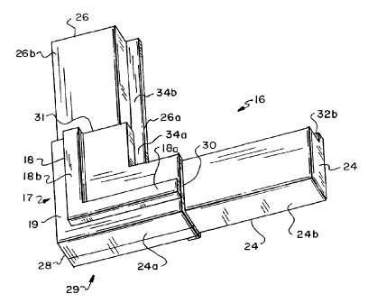
Referring now to Fig. 2, the corner key 16 which supports
the stop 18 includes two legs 24 and 26 which meet at a ninety
s degree angle to form a corner 28. The legs 24 and 26,
respectively, support raised members 18a and I8b which
preferably also meet at a ninety degree angle to form the stop
18. The members 18a and 18b are spaced from the outer edges of
the legs, and thus, define the outer region 19.
The legs 24 and 26 each consist respectively of an upper
section 24a, 26a and a lower section 24b, 26b. The upper
sections 24a and 26a, which meet to form the corner 28 and
support the stop 18, are thicker than the lower sections 24b
and 26b and together form a corner section 29. Accordingly, on
is each leg there is a slight discontinuity, or edge 30 and 31,
respectively, where the upper and lower sections 24a-b and 26a-
b meet. The thinner lower sections 24b and 26b slide into the
ends of the adjacent segments, until the segments are flush
with the edges 30 and 31 of the corner section 29. The
zo segments and the corner section then form an essentially
continuous section of the frame 10 (Fig. 1).
The upper sections 24a and 26a of legs 24 and 26 are
shaped to mate with the frame segments 14. They thus include
U-shaped troughs 32a and 34a, which align with troughs 15 on
zs the segments 14 (Fig. 1). These troughs facilitate the
mounting of the screening 12 to the frame 10. As depicted in
the drawing, Z-shaped troughs 32b and 34b may extend the
lengths of the lower sections 24b and 26b of the legs 24 and
26, for ease of manufacture.
3o Referring still to Fig. 2, each of the members 18a and 18b
of the stop l8 extends approximately one-half the length of the
associated leg 24 and 26. The legs are approximately 2 inches
long, and members are thus about ane inch long. The stop 18 is
so small, when compared to the size of the frame 10 (Fig. 1),
35 that it may be relatively wide without significantly increasing
the weight of the frame or the amount of raw materials used in
making the frame. The stop is easily incorporated into the
104050-2CA
-6-
corner key, which is preferably made of molded plastic and one-
piece. Accordingly, the key, with the integral stop, can be
inexpensively manufactured.
Figs. 3A and 3B illustrate an alternative embodiment 11 of
s the current invention. Fig 3A depicts a window screen frame 11
that includes the four frame segments 14a-d and the two corner
keys 16 that connect the top 14a to the two sides 14b-c, as
shown also in Fig. 1. In addition the frame 11 includes two
corner keys 38 with integral handles 40, that connect the two
side segments 14b-c to the bottom frame segment 14d. The
handles 40 can be used to slide the screen frame vertically
along tracks in the window jamb (not shown). One of these
corner keys 38 also includes the integral stop 18 discussed
above.
~s Fig. 3B depicts the window screen frame 11 configured for
sliding horizontally along the tracks. Accordingly, the two
corner keys 38 with integral handles 40 connect the side 14b to
the top and bottom sections 14a and 14d of the frame. The two
corner keys 16 without handles connect the opposite side 14c to
zo the top and bottom sections.
Fig. 4 depicts the corner key 38 in more detail. In this
drawing the interior side of the key is shown. Accordingly the
stop 18, which is on the exterior side of at least one~of these
keys, is not shown. The corner key 38 includes the two legs 24
zs and 26 which meet to form the corner section 29. In addition
to the stop, the corner section 29 supports the handle 40,
which extends inwardly therefrom. The handle 40 is circular in
the drawing with a finger-sized cavity 41. The handle may be
any shape, such as, for example, square with one of its corners
so pointing toward the corner 28. The handle 40 may be open as
depicted in Fig. 4 or it may be closed with an end wall (not
shown) on the exterior side, to protect the screening 12 (Fig.
1) against tearing caused by fingers poking through the cavity.
A trough between the handle 40 and the interior edges of the
ss corner section 29, which is hidden from view in the drawing,
connects with the troughs 15 on the frame segments 14 (Fig. 3).
These troughs facilitate the mounting of the screening 12 to
the frame.
104050-2CA
_7_
Assembling a frame 11 using the corner keys 32 eliminates
the need to install separate handles. This reduces the time it
takes to complete the frame assembly process, and thus, reduces
the associated cost. Further; it simplifies the manufacturing
s process for the frame segments by eliminating therefrom the
cut-outs associated with these separate handles.
Fig. 5 depicts a lower, left hand corner of a window
assembly 50 constructed in accordance with a second alternative
embodiment. This assembly includes a locking mechanism which
consists of a locking pin 52 that extends through a window
frame 54 and a housing 56 supported by the frame 54. The pin
52 engages a retreat 58 in a corner key 60 of a window screen
frame 61. When the pin 52 enters the retreat 58, the pin
prevents the window screen frame 61 from being moved in either
~s the horizontal or vertical direction. The corner key 60 is
depicted in more detail in Fig. 6.
Referring also to Figs. 7A and 7B, the locking pin 52
includes on the end 52a that engages the retreat 58 a
protrusion 52b and along its length a ridge 51. An opening 55
zo in the housing 56 through which the pin 52 moves, as it is
withdrawn from the retreat 58 and later inserted into the
retreat, is shaped to receive the ridge 51 and the protrusion
52b. The opening 55 thus includes a detent 55a, which receives
the ridge 51 and maintains the pin in proper alignment. As the
zs pin 52 is withdrawn, the protrusion 52b compresses slightly and
ultimately hits an inner wall of the housing 56, which prevents
further withdrawal of the pin. When the pin 52 is fully
withdrawn from the retreat 58, the opening 55 holds the pin, by
friction, to prevent it from inadvertently re-entering the
so retreat 58. The opposite end of the locking pin 52 supports a
handle 53a that is excessible from the interior side of the
window frame 54 and a stop 53b, which prevents the pin 52 from
sliding too deeply into the retreat 58, and thus, out of the
reach of the user.
ss The housing 56 includes an interior face 62, an exterior
face 63 and two legs 64 that extend outwardly therefrom. The
legs are shaped to slide into a detent (not shown) in the
104050-2CA
_g_
window frame 54, such that the frame rests against an indent
64a in each of the legs: In a preferred embodiment, the
housing 56 is supported by a wall 57, which is the interior
wall of the track for the screen.
s Including the retreats 58 in the corner keys 60 avoids
having to include them in the frame segments 14. The retreats
are easily incorporated into the keys, which are preferably
made of molded plastic, and may not be as easily incorporated
into the frame segments. The corner keys may include two
o retreats as depicted in Fig. 6, so that the keys can be used in
any corner of the frame.
Fig. 8 illustrates an alternative embodiment 66 of the
corner key 60 depicted in Fig. 6. The key 66 depicted in Fig.
8 has legs 24' and 26' which have U-shaped cross sections. The
opening 25 in the legs 24' and 26' face the exterior when the
key 66 is installed in an assembled screen frame. Each of the
legs 24' and 26' include a shaped end 68, which inhibits the
associated leg from pulling out of the frame segment into which
the leg is installed. These shaped ends 68 are essentially
Zo flat, with a straight side 70 that forms a tab and an angled,
elongated side 72. The tab 70 extends outwardly from the
associated leg 24' or 26', to widen the end of the leg and
prevent it from pulling out of the frame segment 14 into which
it is inserted. Each of the legs 24' and 26' also includes a
is tab 74, which is proximate to the corner section 67 of the
corner key 66. This tab 74 widens the portion of the leg that
is proximate to the end of the frame segment into which the leg
is installed. This tab 74 thus inhibits the frame segment from
moving away from the corner section 67. This configuration of
so the leg, which reduces the materials used in manufacturing the
corner keys, may be used in any of the keys 16, 38 and 60
discussed above.
Each of these corner keys is relatively easy to
manufacture. These keys include, as integral components,
35 handles and/or stops. The frame segments used in conjunction
with these corner keys thus need not include the segment-long
stops required in prior systems. Accordingly, these segments
~13~~~~
104050-2CA
_9_
are easily and inexpensively manufactured. Also, handles need
not be attached to the frame segments to complete the assembly
of a window screen frame, and the window screen frame that
includes these corner keys can be more quickly, easily and
s inexpensively assembled than prior known frames.
The foregoing description has been limited to specific
embodiments of this invention. It will be apparent, however,
that variations and modifications may be made to the invention,
with the attainment of some or all of its advantages.
Therefore, it is the object of the appended claims to cover all
such variations and modifications as come within the true
spirit and scope of the invention.