Note: Descriptions are shown in the official language in which they were submitted.
1_9 ~ _
WO 93/24 ~ PCf/US93/05147
1
BLOOD EgTRACTION FLOW CONTROL
CALIBRATION BYSTEM AND METHOD
BACKGROUND OF THE INVENTION
1. Field of the Invention
~ This invention relates to a living subject adaptive
blood flow control system and more particularly to an
apheresis blood flow control system which optimizes blood
flow by limiting the blood flow rate in accordance with a
f low control curve determined individually for each donor
or patient subject from actual subject data.' More
particularly, this invention relates to an improved blood
flow control system for controlling and optimizing the rate
of blood withdrawal from a blood vessel, thereby mitigating
the frequency and/or severity of occlusive interruptions '
(e. g. collapse of vein or collapse of tubing in the course
of blood withdrawal.
t
2. Discussion of the Prior Art a
Blood collection systems and apheresis systems such as ,,
i
plasmapheresis, platelet pheresis, therapeutic plasma
exchange or processing, etc. as well as other systems are
known which require the extraction or reinfusion of bodily
fluids from or to a living subject. In the case of a
plasmapheresis system whole blood is extracted from the
subject, plasma is separated from the whole blood, and an
extraction product containing a higher concentration of
blood cells than the whole blood is reinfused back to the
subject while the separated plasma is retained and used for
desired purposes. Frequently, a selected volume of saline
solution or other f luids are infused into the subj ect to
replace the volume of plasma separated from the whole
blood.
To optimize utilization of processing equipment and
support personnel and minimize inconvenience and discomfort
to they subject, it is often desirable to remove bodily
fluids as rapidly as possible. However, physiological
WO 93/24159 ~ PCT/US93/05'147
restrictions on flow rates impose practical limitations on
how fast pumping can proceed.
During extraction, if the pumping rate exceeds the flow
capacity of a vein into which a phlebotomy needle or
catheter is inserted, the intravenous pressure will drop
below approximate atmospheric" pressure and the vein
sidewalls will collapse under atmospheric pressure. In the
following, atmospheric pressure refers to the local
extravascular pressure surrounding the vein in the location
away from the pressure cuff and toward the extremities.
When such collapse of the vein occurs, the blood pump must
be stopped or significantly slowed until the intravenous
blood flow restores the intravenous pressure to a point
greater than atmospheric pressure, thus refilling the
collapsed portion of the vein.
Oftentimes, when the vein collapses about the needle,
the end of the needle will become compressed against the
sidewall of the vein. When this happens the needle will
frequently become embedded within the vein sidewall or will
be sealed to the vein wall by virtue of the negative
pressure within the needle and tubing that can be developed
following a sudden occlusion. The needle then remains
occluded, even after the previously collapsed vein has been
refilled with blood. It may then become necessary to
remove and reposition the needle at the expense of
considerable additional time delay.
Furthermore, whenever the internal vein pressure is
allowed to drop below atmospheric pressure and vein
collapse occurs, increased fluid flow shear can cause
platelet activation or hemolysis. Also, the needle can
cause damage to the endothelial cells along the vein wall,
leading to blood coagulation. This is particularly
undesirable early in the processing, prior to the addition
of anticoagulant, since the initiation of coagulation
WO 93/24159 ~ ~ ~ ~ l~ ~ PCT/US93/OS147
3
cascade can seriously degrade, or make useless, the desired
extracorporeal blood processing.
Predicting the optimal rate at which blood may be
extracted from a blood vessel is difficult because
~ intravascular f low rates and volumes vary considerably from
subject to subject. Even for a given subject, the
intravascular flow rate capacity can vary considerably over
a given time period. When blood is being withdrawn from a
peripheral vein, (e.g. a superficial vein of the
antecubital fossa), moment to moment variations in blood
flow through the peripheral vein may be observed due to
changes in physiological variables and/or
,:
contraction/relaxation of the muscles surrounding the blood
a:_,
vessel. In an effort to maintain relative continuity of
blood flow through the vein it is common practice to
require the donor to engage in alternate
contraction/relaxation of the muscles during the blood
withdrawal process - - usually by squeezing an object held
with the hand adjacent the withdrawal site. If, however,
the donor/subject is less than diligent in squeezing the
object, or if the donor only squeezes the object for
intermittent periods, this may result in extreme variations
in blood flow within the peripheral vein during the blood
withdrawal process.
Attempting to optimize the pump blood f low rate by
sensing f low path pressure adj acent the needle is uncertain
because the pressure drop across the needle varies
substantially with flow rate, hematocrit dependent blood
viscosity and needle size parameters. It is therefore
common to rely on a gravity driven flow rate far below the
optimum or a pumping rate that is known to be well within
the blood flow capacity of most subjects. This may be far
below the optimum flow rate.
One arrangement in which a plasmapheresis system serves
as a reservoir for receiving and returning bodily fluids is
CA 02136419 2002-06-26
L~ _
described in U.S. Patent 4,086,924 to Latham, Jr. for
"Plasmapheresis Apparatus". In this system extraction
occurs under vein pressure and gravity. A multi-rate
blood pump for the plasmapheresis system is accelerated
or decelerated to match this flow rate. Reinfusion occurs
at a predetermined rate with the blood pump set to a
relatively low speed condition.
A more capable blood flow control system is disclosed
in U.S. Patent No. 4,657,529 to Prince, et al. As with
the present system, the system disclosed in the prior
patent utilizes a programmed digital. processor to
regulate blood flow based on sensed fluid pressure in the
flow path. The flow rate, i.e. pump speed, is regulated
to achieve a maximum flow rate consistent with avoiding
vein occlusions. Though the system disclosed therein
provides a significant improvement over prior blood flow
control systems, experience has indicated that in some
instances, due to errors in the slope measurement for the
control curve, it is still possible to create negative
pressure in the blood vessel, resulting in vein collapse.
Thus, what is needed is an improved system and method for
calibrating and controlling fluid withdrawal which
utilizes a more accurate slope calculation, thus
extending the operating range of the system.
SUMMARY OF THE INVENTION
The present invention comprises a system for
withdrawing fluid from the human body at adaptively
controlled flow rates.
In accordance with a broad aspect of the invention,
there is provided an improved method and system for
calibrating and controlling the withdrawal of fluid from
a variable source, such as a blood vessel, at an optimal
rate .-
WO 93/24159 ~ ~ ~ ~ PCf/LJS93/05147
for each subject. The flow control system may comprise a
fluid reservoir fluidly connected to a blood vessel by a
first fluid flow path. A pump is provided for pumping
blood from the blood vessel, through the first fluid f low
5 path to the fluid reservoir. A pressure sensor is provided
for sensing pressure indications, including a zero flow
pressure indication and a series of flow path pressure
measurements, and a flow rate sensor is provided for
sensing the f low rate within the first f luid f low path
. A
f low rate control system is provided to receive and process
the sensed pressure and sensed flow rate indications and to
generate a f low control curve which, in accordance with the
sensed changes in the pressure and f low rate, modulates the
provision of flow rate control signals to the pump. By
obtaining a more accurate zero f low pressure measurement,
and by taking a series of periodic flow path pressure
measurements, a more accurate control curve is generated
than was previously possible.
The control system is generally programmed and adapted
to carry out the steps of the method of the present
invention, and includes the following features:
(a) means for generating an indication of pressure
within the subject at zero flow rate;
(b) means for generating a calibration flow rate curve
comprised of a plurality of periodic flow path pressure
measurements;
(c) means for generating a flow rate control curve
utilizing the slope of said calibration flow rate curve,
said zero flow pressure indication, and a translation from
said zero flow pressure indication corresponding to a
predetenained intravascular pressure value; and
' . (d) means for generating during conditions of normal
operation flow rate control signals limiting the actual
f low rate to a magnitude along the f low rate control curve
.
WO 93/24159 PC1'/US93/05147
~i3b 41~ 6
In accordance with a preferred embodiment of the
invention, the calibration and control system includes a
pressure cuff which is utilized to provide pressurization
of the subject's flesh surrounding the blood vessel to
5~ increase the usable range of operating internal vein
pressures. The pressure cuff pressure provides an
indication of the maximum operating pressure due to the
fact that an internal vein pressure that is higher than the
' cuff pressure would result in all of the blood flowing
under the cuff, precluding withdrawal of some of the blood
flowing into the vein.
Still further in accordance with a preferred embodiment
of the invention, the calibration flow rate curve
generating means includes (i) means for depressurizing the
pressure cuff so that a zero flow rate pressure can be
determined and (2) means for pressurizing the pressure cuff
and means for rapidly and uniformly accelerating said fluid
pump so that a large number of pressure measurements can be
taken periodically. Still further in accordance with a
preferred embodiment of the invention, the calibration flow
rate curve generating means includes means for
mathematically processing the periodic flow path pressure
measurements to obtain a Least-Squares slope approximation.
fin another embodiment, the means for generating a flow
rate curve includes means for adjusting the slope of the
calibration f low rate curve to compensate for changes in
internal vein pressure due to the rapid acceleration of the
blood pump during the calibration period. In one
embodiment, the slope adjusting means includes means for
mathematically processing the periodic flow path pressure
measurements to obtain a Binomial fit having a linear
portion, The linear portion is then extracted to determine
the slope of the control curve. Other mathematical methods
of curve fitting and linear component approximation which
CA 02136419 2000-09-21
7
are known to those skilled in the art can be utilized as
well.
Further, in accordance with a preferred embodiment
of the invention, the fluid control system includes a
control panel coupled to convey operator commands to the
controller. The controller includes a programmed digital
processor which operates for each new subject and
environment to determine zero flow vein pressure and to
determine the slope of a subject dependent control curve
based upon the generated calibration flow rate curve.
The control curve which is generated is within the
substantially linear flow rate capacity of the subject
and is generated from the zero flow pressure point, the
calibration flow rate curve, and an empirically
predetermined pressure offset. The controller then
commands the fluid pump to maintain the system at a
desired maximum nominal flow rate subject to any
limitations imposed by the flow rate control curve.
In a preferred embodiment, the digital processor
operates on discrete (e. g. 50 msec) computer cycles.
Such computer cycles periodically update flow rate
commands to the pump. During each computer cycle the
processor (a) samples the sensed pressure, (b) provides
atmospheric calibration therefor and, then, (c) provides
stability compensation to generate a compensated pressure
value. The actual flow rate is also calculated and
updated in response to a pump motor velocity count signal
and then used to find the pressure intersection point on
the control curve at the actual flow rate. The actual
sensed pressure is subtracted from the control curve
intersection pressure point to produce a pressure error
value.
CA 02136419 2000-09-21
7a
According to one aspect of the invention, there is
provided a system for calibrating the control of the flow
of fluid in a given direction to or from a subject having
a limited flow rate accommodation comprising: a pressure
cuff coupled to the subject to provide pressurization of
the subject's blood vessel to increase the dynamic range
of operating internal vein pressures; a fluid pump that
is connectable in fluid pumping relationship along a
fluid flow path between the subject and a fluid processor
or reservoir; pressure sensing means coupled to sense
fluid pressure in the fluid flow path between the fluid
pump and the subject and generate indications of the
sensed pressure; a flow rate sensor coupled to provide an
indications of fluid flow rates along the first fluid
flow path; and a fluid pump control system coupled to
receive the sensed pressure and flow rate indications and
provide to the fluid pump flow rate control signals in
response thereto, the fluid pump control system
including:
(a) means for inflating and deflating the pressure
cuff;
b) means for generating a zero-flow point,
including means for sensing the internal fluid pressure
within the subject's blood pressure at a zero flow rate
while the pressure cuff is deflated, the zero flow point
being an indication of pressure within the subject at
zero flow rate;
c) means for making periodic flow path pressure
measurements while the pressure cuff is inflated and
means for generating a calibration flow rate curve
comprised of the plurality of periodic flow path pressure
measurements;
CA 02136419 2000-09-21
7b
d) means for generating a flow rate control curve
utilizing the slope of the calibration flow rate curve,
the zero-flow point, and a translation from the zero-flow
point corresponding to a predetermined intravascular
pressure value; and
(e) means for generating control signals limiting
the actual flow rate to a magnitude along the flow rate
control curve.
According to another aspect of the invention, there
is provided a method of controlling a flow rate of a
bodily fluid along a flow path between a subject and a
processor or reservoir comprising the steps of: placing a
deflated pressure cuff on the subject; sensing the
internal fluid pressure within the subject's blood vessel
at zero flow rate while the pressure cuff is deflated and
generating a zero-flow pressure point; inflating the
pressure cuff, waiting until the vein pressure
stabilizes, initiating a blood draw, and making a
plurality of periodic flow path pressure measurements;
using the flow path pressure measurements to generate a
calibration flow rate curve; generating a flow rate
control curve utilizing the slope of the calibration flow
rate curve, the zero-flow pressure point, and a
translation from the zero-flow pressure point
corresponding to a predetermined intravascular pressure
value; and generating during conditions of normal
operation flow rate control signals limiting the actual
flow rate to a magnitude along the flow rate control
curve.
According to a further aspect of the invention,
there is provided a system for calibrating the control of
the flow of fluid in a given direction to or from a
subject having a limited flow rate accommodation
CA 02136419 2000-09-21
7C
comprising: a pressure cuff coupled to the subject to
provide pressurization of the subject's blood vessel to
increase the dynamic range of operating internal vein
pressures; a fluid pump that is connectable in fluid
pumping relationship along a fluid flow path between the
subject and a fluid processor or reservoir; pressure
sensing means coupled to sense fluid pressure in the
fluid flow path between the fluid pump and the subject
and generate indications of the sensed pressure; a flow
rate sensor coupled to provide an indications of fluid
flow rates along the first fluid flow path; and a fluid
pump control system coupled to receive the sensed
pressure and flow rate indications and provide to the
fluid pump flow rate control signals in response thereto,
the fluid pump control system including:
(a) means for inflating and deflating the pressure
cuff;
(b) means for generating a zero-flow point,
including means for sensing the internal fluid pressure
within the subject's blood pressure at a zero flow rate
while the pressure cuff is deflated, the zero flow point
being an indication of pressure within the subject at
zero flow rate;
(c) means for generating a calibration flow rate
curve including means for rapidly and uniformly
accelerating the fluid pump while the pressure cuff is
inflated so that a plurality of flow path pressure
measurements can be taken periodically;
(d) means for generating a flow rate control curve
utilizing the slope of the calibration flow rate curve,
the zero-flow point, and a translation from the zero-flow
point corresponding to a predetermined intravascular
pressure value; and
CA 02136419 2000-09-21
7d
e) means for generating during conditions of normal
operation flow rate control signals limiting the actual
flow rate to a magnitude along the flow rate control
curve.
According to another aspect of the invention, there
is provided a system for calibrating the control of the
flow of fluid in a given direction to or from a subject
having a limited flow rate accommodation comprising: a
pressure cuff coupled to the subject to provide
pressurization of the subject's blood vessel to increase
the dynamic range of operating internal vein pressures; a
fluid pump that is connectable in fluid pumping
relationship along a fluid flow path between the subject
and a fluid processor or reservoir; pressure sensing
means coupled to sense fluid pressure in the fluid flow
path between the fluid pump and the subject and generate
indications of the sensed pressure; a flow rate sensor
coupled to provide an indications of fluid flow rates
along the first fluid flow path; and a fluid pump control
system coupled to receive the sensed pressure and flow
rate indications and provide to the fluid pump flow rate
control signals in response thereto, the fluid pump
control system including:
(a) means for inflating and deflating the pressure
cuff;
(b) means for generating a zero-flow point,
including means for sensing the internal fluid pressure
within the subject's blood pressure at a zero flow rate
while the pressure cuff is deflated, the zero flow point
being an indication of pressure within the subject at
zero flow rate;
c) means for generating a calibration flow rate
curve including means for rapidly and uniformly
CA 02136419 2000-09-21
7e
accelerating and decelerating the fluid pump while the
pressure cuff is inflated so that a plurality of flow
path pressure measurements can be taken periodically;
(d) means for generating a flow rate control curve
utilizing the slope of the calibration flow rate curve,
the zero-flow point, and a translation from the zero-flow
point corresponding to a predetermined intravascular
pressure value; and
e) means for generating during conditions of normal
operation flow rate control signals limiting the actual
flow rate to a magnitude along the flow rate control
curve.
The pressure error signal is then integrated and
scaled to produce a flow control command. The integrator
is subjected to a lower limit of zero, an upper limit
equivalent to the maximum flow rate, and a rate of change
WO 93/24159 ~~ ~ ~ ~ PCT/US93/05147
8
limit to produce an adjusted flow control command which, is
applied as a flow rate command to a digital feedback flow
rate control servo loop.
A forward portion of the servo loop includes a flow rate
error integrator, a staler and.a D-A converter coupled to
apply an integrated flow rate error signal to a pulse width
modulated (pwm) motor control system which is itself a
servo loop and drives the pump motor. A velocity signal
from the pump motor is provided as feedback to the pwm
motor control system and through a stability compensating
calculation to provide the updated flow rate values which
are used in accessing the flow rate limit curve and in
determining the flow rate error signal in the flow rate
servo loop. Actual flow rates and actual pressures contain
scaling errors due to tubing geometry and hardness, and
pressure sensor scale errors. However, since the system
adapts by measuring all calibration points with
substantially the same scaling errors as are experienced at
other flow rates and corresponding pressures, these errors
are substantially eliminated, to the extent that the
scaling errors are constant linear functions. That is, the
system operates in its own f low and pressure units which
are determined by the instant tubing and pressure sensor
involved. Compensating corrections for pump or tubing
nonlinearity may also be provided for large negative
pressures wherein the polyvinylchloride tubing, which has
a relatively low hardness, tends to flatten somewhat within
the peristaltic roller pump and therein exhibits a
correspondingly somewhat reduced flow rate than that which
is calculated from an ideal linear extrapolation of data
measured at lower magnitude negative pressures.
Other control systems and methods, which are known to
those skilled in the art, can be utilized for operating the
fluid withdrawal system in accordance with the requirements
of the control curve generated by the invention.
WO 93/24159 ~ ~ ~ 1 ~ ~ PCT/US93l05147
9
It is thus an object of the present invention to provide
an improved system and method for calibrating and
controlling the withdrawal of fluid from a blood vessel by
generating and utilizing an improved flow control curve to
maximize fluid withdrawal without occlusion or collapse of
the blood vessel.
BRIEF DESCRIPTION OF THE DRAWINGS
A better understanding of the invention can be had from
a consideration of the following detailed description,
l0 taken in conjunction with the accompanying drawings in
which:
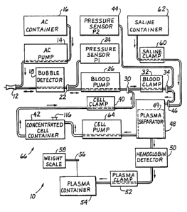
Fig. 1 is a schematic and block diagram representation
of a fluid flow path fc~ a plasmapheresis system using an
adaptive body fluid flow control system in accordance with
the invention;
Fig. 2 is a graphical illustration of a dynamic
pressure-flow curve having an operating point that
intersects an actual pressure-flow curve;
Fig. 3 is a graphical illustration of the control curve
generated in prior art control system;
Fig. 4 is a graphical illustration of an erroneous
control curve generated in a prior art control system;
Fig. 5 is a graphical illustration of variations in the
slope of the control curve in a prior art control system;
Fig. 6 is a graphical illustration of donor extraction
data in a prior art control system;
Fig. 7 is a graphical illustration of the calibration
flow rate curve and zero-flow pressure measurement in
accordance with the invention; and
Fig. 8 is a graphical illustration of an extraction flow
rate control curve in accordance with the invention.
DETAILED DESCRIPTION OF THE ILLUSTRATIVE EMBODIMENT
The detailed description set forth below in connection
with the appended drawings is intended merely as a
WO 93/24159 PCT/US93/05147
213b4~.~~ 1°
description of an illustrative embodiment of the invention,
and is not intended to represent the only form in which the
present invention may be constructed or utilized. The
description sets forth the functions and sequence of steps
for construction and implementation of the invention in~
connection with the accompanying figures. It is to be
understood, however, that the same or equivalent functions
and sequences may be accomplished by different embodiments
that are also intended to be encompassed within the spirit
and scope of the invention.
Referring now to Fig. 1, there is illustrated a
noninvasive, sterile plasmapheresis flow path 10 for a
plasmapheresis system utilizing an adaptive bodily fluid
flow control system in accordance with the invention.
Intravenous connection of the flow path 10 to a subject is
provided by a bodily fluid flow channel connection such as
a phlebotomy needle 12 which is suitable for insertion into
a vein of a subject to provide communication of blood
and/or other fluids between the subject and the flow path
10 of the plasmapheresis system.
The flow path branches immediately adjacent the needle
12 with one branch extending through a noninvasive
peristaltic anticoagulant pump 14 to an anticoagulant
container l6. During a whole blood extraction cycle the
anticoagulant pump l4 operates to supply'and mix a small
percentage of anticoagulant with the blood as it is being
extracted to prevent activation of clotting mechanisms to
prevent clotting and clinging of the blood to tubing
sidewalls as it passes through the flow path 10. By mixing
the anticoagulant with the whole blood at the needle 12
during extraction, the two fluids become fully mixed and
less anticoagulant is required. This is a desirable effect
which helps minimize the amount of anticoagulant in the
separated plasma.
CA 02136419 2002-06-26
11
The other branch of the blood flow path 10 extends through
a bubble detector l8 to another branch point 22. From branch
point 22 one branch extends to a P1 pressure sensor 24 coupled
to sense fluid pressure on the subject side of a blood pump
26. The pressure sensor 24 includes a disposable filter
coupling the sensor to a pressure sensor tube 28 so as to
maintain a noninvaded sterile atmosphere within the flow path
10. The second branch from branch point 22 extends through the
noninvasive, peristaltic blood pump 26 to a branch point 30.
From branch point 30, one branch extends through a blood
clamp 32 to another branch point 34. The other flow path at
branch point 30 extends through a cell clamp 40 to the bottom
of a concentrated cell container 42 which receives, and
temporarily stores pending reinfusion, high hematocrit blood
after a substantial portion of the plasma has been separated
therefrom.
From branch point 34, one path extends to a second, P2
pressure sensor 44 while the other path extends through a
branch point 46 to a plasma separator 48 which encloses a
filter 49.
While the exact nature of the plasma separator 48 is not
material to the present invention and can be fully
conventional if desired, a highly advantageous plasma
separator is a rotating filter type of separator as
illustrated in US Patent 5,194,145 (March 16, 1993) for
"Method and Apparatus for Separation of Matter From
Suspension" by Donald W. Schoendorfer. For this type of
separator the end product plasma output is coupled through a
hemoglobin detector 50 and a plasma clamp 52 to a plasma
container 54 which is maintained at atmospheric pressure. The
plasma container 54 is suspended from a tension arm 56 to a
weight scale 58 which provides feedback to the plasinapheresis
system of the amount of plasma within container 54. Since P2
pressure sensor 44 is coupled to
WO 93/24159 ~~ ~'~~ PCT/U~93/OS147 . ~~
12
the inlet of plasma separator 48 and since the plasma
outlet of separator 48 is maintained at atmospheric
pressure plus a small adjustment for vertical height .
differences, the pressure sensor P2 44 provides an
~ indication of tra~nsmembrane pressure far the filter
membrane within plasma separator 48. This transmembrane
pressure indication can be useful in monitoring and
controlling the operation of plasma separator 48.
Another flow path from branch point 46 extends through
a saline clamp 60 to a saline container 62. This flow path
enables the separator to be initially primed with a small
amount of saline prior to initial use, to be cleansed with
saline after final use, and provides a flow path of saline
solution from the saline container 62 through branch point
46 to branch point 34 and then through blood clamp 32 to
blood pump 26 and bubble detector 18 to phlebotomy needle
12. This path enables saline solution to be communicated to
the subject at the end of a plasmapheresis operation to
provide fluid replacement of any plasma removed from the
whole blood of the subject.
A cell pump 64 is coupled between an outlet of plasma
separator 48 on the same side of the membrane as the inlet
at the top of concentrated cell container 42. Cell pump 64
thus controls the flow of high hematocrit blood from plasma
separator 48 to concentrated cell container 42 where the
high hematocrit blood is temporarily stored during an
extraction subcycle. Whenever the concentrated cell
container 42 becomes full, a reinfusion subcycle is
executed in which cell clamp 40 is opened, blood clamp 32
is closed, and blood pump 26 is operated in the reverse
direction to transfer the high hematocrit blood from
concentrated cell container 42 back to the subject through
bubble detector 18 and phlebotomy needle 12.
. ,
The entire bodily fluid flow path 10 including all of
the branch points 22, 30, 34, 46 and the interconnecting
WO 93/24159 ~ PCT/US93/05147
13 ~~~ ~ ~ ,
tubing 66 are comprised of inexpensive, disposable
materials which may be presterilized. The blood flow path ~iv
is maintained completely noninvasive so as to protect ~'"
against contamination and prevent and maintain sterility of 'v'
' the bodily fluids. The non-hardware portion of the flow
path may be fully replaced for each different subject.
Even the plasma separator 48 may be constructed such that
only a sterile, disposable, portion comes into contact with
the bodily fluids. The risk of transmitting disease to the
a.
subject during the plasmapheresis operation is thereby
minimized.
In order to optimize use of the plasmapheresis equipment
and maintenance personnel while minimizing inconvenience
and discomfort to the donor subject, it is desirable to
accoaplish a plasmapheresis procedure as rapidly as
possible. Typically, the factor which limits the '
plasmapheresis operating rate is the intravenous blood
volume and/or intravenous flow rate within the blood vessel
from which blood is being extracted and/ or into which olood
is being infused. It is desirable to continually attempt
to withdraw blood from the blood vessel at a relatively
fast rate (e.g. 150 m1/min:) and, indeed, experience has
taught that many human subjects are able to withstand and
support consistent withdrawal and/or infusion of fluids at
such relatively high rate (e.g. 150 ml/min.) without any
incidence of vein collapse or regional depletion of
available intravascular volume. However, even when
momentary depletion or diminution in the available
intravascular volume is observed, it is desirable to effect
short term downward adjustments or pauses in the withdrawal
rate, but thereafter, to once again attempt to increase the
withdrawal rate toward a predetermined maximum (e.g. 150
ml/min.;') so as to effectively challenge the system and the
donor to accomplish the withdrawal at the fastest possible
WO 93/24159
PCT/US93/05147
14
rate for that particular human subject, under the then
present conditions.
The adaptive blood f low control system of the . present _
invention is operable to determine the maximum available
flow rate for extraction and ~to control the operation of
the blood pump 26 such that the blood pump will operate
either at a reduced maximum rate (e.g. less than 150
ml/min.) or at a preset maximal flow rate (e.g. 150
ml/min.) if the donor subject can accommodate such preset
maximum rate.
It should be emphasized that the system can be utilized
to calibrate and control the infusion or reinfusion of
blood into the subject according to the same principles as
outlined herein for extraction and someone skilled in the
art would be able to utilize the system and method
disclosed herein for that purpose as well.
A vein supplying or receiving intravenous bodily fluids
through the phlebotomy needle 12 can be analogized to a
small diameter, thin walled, rubber tube. Normally, the
body maintains a pressure within the vein of approximately
10 mmHg above atmospheric. This is sufficient to maintain
the vein expanded and permit normal blood f low. However,
if blood is extracted faster than it can be supplied by the
vein, the pressure within the vein drops toward
atmospheric, causing the external atmospheric pressure
against the body to collapse the vein. Blood flow can be
reinstated by terminating pumping through the needle until
the depleted blood volume is replaced and normal vein
pressure is restored within the vein. However, frequently
the sidewalls of the vein engage the end point of the
phlebotomy needle as the vein collapses to thereby occlude
blood flow through the needle. Even as the vein reexpands,
the needle may remain occluded against the vein wall and it
then becomes necessary to reposition the needle. This of
course imposes considerable time delay and may cause donor
WO 93/24159 ~ ~ ~ ~ ~ ~ ~ 1'CT/US93/05147
anxiety. Clotting processes may be initiated due to high
blood shear and occlusion of the needle against the vein
wall may cause endothelial cell damage.
During venPpuncture it is common to place a pressure
5 cuff around the upper portion of the subject's arm with a
pressure of about 60 mmhg to make pressurize the vessel.
Tn the prior art system disclosed in U.S. Patent No.
4,657,529 to Prince, et al., the goal of the system is to
insure that the internal vein pressure is maintained
10 between atmospheric pressure and the inflation pressure of
the pressure cuff. If the internal vein pressure drops
below atmospheric pressure, the vein will collapse. If, on
the other hand, the internal vein pressure exceeds the
inflation pressure of the pressure cuff, then the blood
15 will pass under the cuff and not be removed. Thus, if the
internal vein pressure is maintained within this range, the
vein will not collapse, and substantially all of the blood
entering the vein will be removed.
To maintain the internal vein pressure within the
acceptable range, it is necessary to obtain an accurate
indication of the zero-flow pressure inside the vein, and
to determine the linear relationship between blood f low and
the pressure drop across the needle. With this
information, the actual pressure inside the vein can be
calculated continuously for all flow rates, and can be
maintained within the bounds of atmospheric pressure and
pressure cuff pressure.
In general, whenever blood is f lowing through needle 12
within a vein, the pressure sensed at pressure sensor 24 is
the sum of the internal vein pressure and the negative
pressure drop across the needle, assuming a negligible
pressure drop within the tube set or in the vein near
needle ,12. This is illustrated in Fig. 2, where internal
vein pressure at zero blood flow is shown at point Pv. As
blood flow increases and the negative pressure drop across
WO 93/24159 ~ PC.T/US93/05147
16
the needle adds to P1, the value of P1 pressure
continuously decreases in a linear fashion as illustrated
by needle/blood pressure characteristic curve 70. As
measured at pressure sensor 24, the actual sensed pressure
will follow a curve 72, which if continued will approach
atmospheric pressure inside the vein, causing vein
collapse. Thus, it is possible, in principle, to obtain an
operating point 74 from the intersection of the sensed
pressure curve 72 with pressure characteristic curve 70.
If Pv is in fact the appropriate internal vein pressure,
then operating point 74 will insure that the system
operates within the acceptable parameters.
In the prior art system of Prince, et al. during
extraction the pressure within the cuff is reduced to about
40 mmHg Thus, the zero-flow rate (through needle 12)
internal vein pressure is determined largely by the cuff
presssre during extraction and is approximately 24-40 mmHg
The determination of the linear pressure-flow relationship
in this system is illustrated in Fig. 3. In order to
determine the flow characteristics of the needle and blood
combination, the pressure at two f low points between the
needle 12 and blood pump 26 is measured. The first point
is the zero-flow rate point 76, which we have determined
will occur, approximately, at the pressure cuff pressure.
The second.point 78 is at 50 ml/min, which is expected to
be well within the flow rate capability of the subject.
From points 76 and 78 a linear calibration flow rate curve
80 is generated. The linear calibration flow rate curve 80
is then translated downward by an amount equal to a
difference in pressure between the 40 mmFig pressure at the
zero-flow rate point 76 and a minimum acceptable internal
vein pressure, such as 4 mmFig, at point 82, to generate a
translated contzol curve 84, coextensive with the actual
needle/blood pressure characteristic curve 85, which is
represented by a dashed line.
WO 93/24159 ~ ~ ~ ~ ~ ~. ~ PCT/US93/05147
17
As disclosed in Prince, et al., alternate control curves
can be generated for subject donors of low blood flow
capability or subject donors with small veins. These
alternate curves are generated by rotation of control curve
~ 84. Prince, et al, further discloses the development of an
error signal, after calibration, between control curve 84
and the measured pressure during operation. The error
signal is processed and used in a closed loop feedback
control system to stabilize pump 26 at a flow rate along
control c~.rve 84.
Fig. 3 shows the operation of the system for two
different internal vein blood flows, Q1 and Q2. Q1 has its
corresponding sensed pressure curve 86 which intersects
control curve 84 at operating point 88 and Q2 has its
corresponding sensed pressure curve 90 which intersects
control curve 84 at operating point 92.
It is important to appreciate that stabilizing blood
flow anywhere along control curve 84 results in the
internal vein pressure Pv at point 82. This is because the
slope of control curve 84 is identical to the slope of the
pressure characteristic curve 85. That is to say, the
linear needle/blood flow relationship, demonstrated by
pressure characteristic curve 85, allows an extrapolation
back to the zero-flow point 82. This is due to the fact
that at point 82 there is no pressure drop across the
needle, which acts as a pressure monitor within the vein.
However, the internal vein pressure Pv will only coincide
with the end point of control curve 84 if the slope of
control curve 84 is equal to the slope of the pressure
characteristic curve 85.
Since the goal of the system is to maintain internal
vein pressure Pv comfortably above atmospheric pressure
(zero on the pressure axis) and comfortably below cuff
pressure (usually 40 mmhg), it is essential that the slope
of the pressure characteristic curve 80 and the pressure
WO 93/24159 ~ ~ PCT/US93/05147
.. . 18
offset be accurately determined. If there is an error in
the slope measurement, then internal vein pressure point Pv
will not reside at the endpoint of control curve 84, since ,
the control curve slope will not accurately reflect the
slope of the pressure characteristic curve 80.
Fig. 4 illustrates a~~control curve 84' which was
generated from two points according to the prior art
system. Points 76' and 78' constitute errors resulting in
control curve 84' having a slope that is steeper than the
actual needle/blood flow relationship which is exemplified
by the actual pressure characteristic curve 85'.
In the prior art system, the generated control curve 84'
is used to increase blood flow until the corresponding
sensed pressure curve 86' intersects control curve 84' at
operating point 88' to satisfy the feedback system.
Extrapolating back from this intersection point 88' along
actual pressure characteristic curve 85' indicates that the
internal vein pressure paint Pv is negative, resulting in
vein collapse. Thus, large errors in slope determination
are detrimental to the operation of the system.
It is also the case that errors in the calculation of
the zero-flow pressure measurement, point 76' in Fig. 4,
1
result in errors in the offset pressure point 82' . This
contributes to operational degradations such as vein
occlusion if point 82' is too low, or insufficient blood
flow withdrawal if point 82' is too high. Similarly, at
point 78' there is a variation in the pressure value at the
time point 78' is recorded, depending upon how close
extraction flow (Qdraw) is to internal vein blood flow
(Qin) .
Fig. 5 illustrates how variations in measured points A
and C can result in wide variations in linear calibration
flow rate curves 80 " . In the prior art method, the slope
. ,
of the control curve is determined by taking a zero-flow
calibration pressure value (point A) and a pressure value
WO 93/24159 1~ ~ ~ ~ ~ ~ ~ (~ PCT/US93/05147
when the fluid draw is assumed to be less than Qin (Point
C) .
If Qin is very high, such as 180 ml/min, then when the
drawn blood Qdraw is zero, resulting in a high zero-flow
pressure point 76' ' , pressure within the vein may become
somewhat higher than the pressure cuff pressure value 94. w
This is due to the fact that a driving force is required to
push the high blood flow through the venous regions
compressed by the pressure cuff. At the point C
measurement, high input vein flow Qin produces a relatively
high value point 78 " '.
On the other hand, if Qin is very small, such as 55
ml/min, then the pressure within the vein may be
substantially lower. In fact, since the pressure cuff is
not infinitely long, edge effects cause the cuff's
inf luence within the arm to be less than the pressure 94 '
within the pressure cuff, as illustrated by pressure points
f.
76' " and 78" .
Thus, depending upon how close Qdraw is to Qin, there is
a variation in the pressure value at the time points A and
C are recorded, as shown by points 76 " and 76 " ' and
points 78 " and 78' " , respectively. These variables can ,
cause significant variations in the actual pressure
measured for points A and C, from donor to donor and from
cycle to cycle.
These variations in points A and C will result in large
variations in the slope of the calibration flow rate curve
as well as in the offset location of control curve 84.
Consequently, these variations will result in inappropriate
control curves.
In Fig. 6, actual data is plotted showing P1 pressure
versus blood flow using the prior art control curve
calibration system. In this case, the slope of the
needle/blood f low characteristics was incorrectly measured,
and is too steep. The trajectory of the two occlusions is
seen where the pressure rapidly goes negative, followed by
a rapid reduction of blood flow. The data points are taken
one second apart. ,
In order to generate a more accurate control curve, for
5' example in wide-range uses such as 30 ml/min to 150 ml/min
extraction control systems,, -vit is imperative that the zero-
flow pressure measurement and the needle/blood pressure- ~'
flow relationship be more accurately established. T h a
method of generating a more accurate control curve in
accordance with the invention is illustrated in Figs. 7 and
8. Calibration is improved in two ways; (1) zero-flow
pressure point 100 is measured without the uncertainties
introduced when the pressure cuff is pressurized, and (2)
the needle/blood pressure flow-relationship is measured
quickly at many points, while the internal vein pressure
does not have time to change significantly, providing
improved accuracy in the slope of linear calibration flow
rate curve 110.
Prior to the initiation of calibration blood draw, the
pressure cuff is deflated. Typically, the venous pressure
stabilizes within a few seconds to a more repeatable range
than when the cuf f is inflated. With the cuf f inf lated,
the time constant of pressure stabilization is often twenty
seconds or more whereas it is about three seconds with the
cuff deflated. Thus, a more accurate zero-flow, internal I-
vein pressure measurement is obtained quickly. The
deflated cuff zero-flow pressure measurement point includes
any gravitational offset involved that is a function of the
donor chair height. Hereafter, this measurement will be
termed the zero flow point.
After the zero-flow point is obtained, the cuff is
pressurized and the vein pressure is allowed to stabilize.
Blood pump 26 is accelerated reasonably rapidly and
uniform~:y and a large number of pressure measurements 120
are taken periodically. For example, 160 values may be
WO 93/Z4159 PCT/US93/05147
21 ~~3~41~
taken over an eight second acceleration of the blood pump.
These pressure and blood flow values are fitted to ~a
pressure-flow acceleration curve 110 which is assumed to
have a constant internal vein pressure during pump
~ acceleration. Fig. 7 illustrates two such calibration
curves 110' and 110" , which could be derived from the data
points 120. It should be noted that the possible
variations between curves 110' and 110" are not very
sign i f icant .
In a preferred embodiment the pressure and blood flow
values 120 are mathematically processed to obtain a Least-
Squares slope estimation. In another embodiment a Binomial
Fit of data points 120 can be utilized with the linear
portion extracted to determine the slope. This method will
permit correction of the slope estimation to reflect
changes in internal vein pressure that occur during the
calibration period. Oth~~~ mathematical methods of curve
w fitting which are known t.. hose skilled in the art can be
utilized as well.
In another preferred e~:::odiment, the blood pump may be
first accelerated to a peak value such as 30 ml/min and
then decelerated back to 0 ml/min and pressure-flow values
may be taken over the acceleration and deceleration in
order to compensate for changes in the internal vein
pressure during the calibration period.
Fig. 8 illustrates the generation of the control curve
130 in accordance with a preferred embodiment of the
invention. The control curve zero intercept point 140 is
established above point IOO by an empirically determined
pressure offset value 150, which, in a preferred
embodiment, is a fraction of a maximum operable internal
vein pressure. The pressure offset value 150 is determined
by taking into consideration variations in the zero-flow
point and variations in the maximum operable vein pressure
from subject to subject. These variations are used to
WO 93/24159 PCT/US93/05147
22
1'~6 ~
provide a typical operating vein pressure range within
which a comfortable margin can be obtained. This pressure
range is between atmospheric pressure and the pressure cuff .
a
pressure. Thus a pressure offset is constructed which is dv'
5~ comfortably above zero-flow point 100 while still allowing
;.::
for small dynamic variations above and below control curve
130.
In a preferred embodiment, pressure offset value 150 is
between the deflated cuff zero-flow point 100 and cuff
pressure value 94. In a preferred embodiment, pressure i'v
;:
offset 150 is a fraction of the cuff pressure value 94
above the zero-flow point 110, such as one-quarter of cuff
pressure value 94. Thus, a control curve l3Q is utilized
;r
which has an endpoint 140 that is between zero-flow point
100 and cuff pressure value 94. This insures that the
internal vein pressure is maintained below cuff pressure
94, permitting substantially total blood withdrawal, and
above the zero-flow point, preventing vein occlusion.
While what has been shown and described above is an
adaptive calibration and control system which is
particularly useful for controlling bodily f luid f low rates
in a plasmapheresis system for the purpose of enabling a
person of ordinary skill in the art to make and use the
invention, the invention is not limited thereto. It will
be appreciated that the principles disclosed herein have a
broader applicability then has been discussed, such as
larger vein use, higher blood flow, and for use with other
means of extracting blood, such as catheters and arterial
shunts. Accordingly, any modifications, variations or
equivalent arrangements within the scope of the attached
claims should be considered to be within the scope of the
invention.