Note: Descriptions are shown in the official language in which they were submitted.
~ ~36453
Returnable Packaging Sys~em
The invention applies to a returnable packaging system
encompassing returnable packagings in accordance with the
preamble of the C~aim 1.
In the sphere of packing, the cardboard box still represents the
dominating means of transport, this applies in particular to consumer
goods. The goods packed in cardboard boxes are generally placed as
individual units in pallets, secured with self-adhesive tapes, tightening
straps or by shrink films and this state delivered to the retail trade. It is
a method producing waste in the.form of shrink films, self-adhesive
tapes etc. and expecially as cardboard boxes which, in Germany,
account for several 10,000 tos of waste per annum. Due to and in the
face of ever more stringent environmental regulations aimed at
alleviating the increasing lack of landfill capacities, new concepts are
strived for in the packaging industry; concepts by which the now
resorted to one-way packages can be replaced by a system of
returnable ones.
Such a returnable packaging system can, according to the state-of-art
technology, be realized by several methods. In the field of returnable
packages endeavours are chiefly directed at minimizing additional
transport volumes during the recycling of the packages, i.e. the return
of same to the manufacturers or the trade, respectively. Proposed as
solution to the problem are especially containers being collapsible or
those which can be space-savingly stacked into each other.
Introduced are, moreover, containers conceived to a modular system
enabling a random selection of container volumes by varying the
container modules.
Offered and evaluated as to the returnable transport containers are
various concepts. The conventional methods are, however, conceived
to~a system by which the individual modules are allotted to a particuiar
system, preventing their combination with non-system modules. This
results in disadvantages as to the exploitation of space and technical
storage problems if various modular systems have to be transported.
It is by this system, moreover, impossible to combine these modular
elements, of a particular configuration, size and design with other
systems and thus preparing for a returnable transport container.
Declared purpose and aim of this invention is the creation of a system
by which various module elements of a modular system can be
2136~5~
combined and various modular systems can be simply and cost-
effectively executed.
This objective is being attained by the characteristic features of'Claim
1; the consequential developments of the invention being
characterized by the features as described in the sub-claims.
As claimed by the invention, the combinable modular elements as, for
instance, the traylike bottom/cover elements or wall frame elements,
provide an interRacing configuration beyond the scope of the
appertaining element, so that the individual elements independently of
their size and design possess an interRacing configuration which
allows their combination with other modular elements.
In accordance with the advanta~eous design of the invention, the
interface is, by the forming of tongue and groove joints, preferably
with directly adjoining tongues and grooves, shaped in the range of
the top edge of the modular elements. The direct transition between
tongues and grooves is virtually steplessly formed in the form of an
inclining line. The gradient of the inclining face corresponds with the
gradient of the inclined faces with the tongues and recesses opposite
the interRacing line being given as preferably 30.
The tongues and grooves engage with the corresponding grooves and
tongues of an opposite modular element establishing thus a
connection or interlocking of the elements. For this purpose the
tongues and grooves may extend over the whole width of the
interRacing edge, but may also be more narrow than the edge of the
inteRacing edge. The interRacing edge may, in this connection,
especiaily in the instance of modular elements forming bottom or lid
elements, take the shape of a seam ledge projecting to the front.
In order to provide the inner edge of the container with a uniform
height, it may be of advantage to form the tongues and grooves on the
outer edge of the inteRaces narrower than the wall thickness of the
interRacing edge.
For improving the handling of the modular elements during the
assembly, the tongues/grooves are preferably cone shaped. With the
above described edge layout of the tongues, the outer faces of same
are in alignment with the preferably straight outside wall of the
container. In this case next to the laterally inclined faces only the
irlner faces of tongues/grooves contribute to forming the conical
shape~ of tongues and recesses. The forming of the inner face of the
~1364~3
tongue with an inclination to the outside conveniently provides for
problemless interstacking of similar lid and bottom elements.
Tongues and grooves are furthermore advantageously dimensioned,
so that the top edge of the tongues, running parallelly with the cutting
plane, are positioned flush with corresponding face of the grooves
thus contributing to the load dissipation of the supported modular
elements.
In respect to the shaping of the interface it is advantageous from
engineering as well as design aspects, to provide each one tongue
and one groove in the direct vicinity as inteRace forming elements. A
certain number of these tongues/grooves is appointed uniformly in "a
row", i.e. in an alternative sequence over the scope of the interface.
This layout "in a row" provides fbr a further degree of freedom in
respect of establishing connections as the modular elements can be
appointed in two positions for engaging with each other by turning
through 180 on a vertical axis of the container.
In consideration of the execution examples presented it is
advantageous to provide rectangular containers with each two pairs of
tongues/grooves regularly placed over the area of each side.
The interface configuration can, furthermore, be characterized by
suitably located closure elements thus providing not only for one safe
connection respectively ensuring a secure stacking of the modular
elements. Recourse may, for instance, be taken to catch or snap-on
noses located within the area of the inteRace and effecting a secure
locking of same. Particularly suitable for this purpose are semi-
circular undercut snap-on noses which are also placed flush on the
outside of the container. In another advantageous execution are,
within the range of the interface, pin-shaped projections engaging with
a complementary design of the opposite modular element thus
forming two semi-circular contacting pins locked with a ring element.
Such ring eiements may advantageously take the form of so-called
original securing rings which, for instance, engage in a groove
provided on the pin side in such a manner that a disengaging of the
ring invariably causes its destruction. Modules may also be secured
preferably with a hot water soluble glued connection.
The utilization of wall frame elements, being collapsible for the
purpose of volume reduction during the return transport, demand
especially for a unrestricted compatibilit,v of the interfacing
~configuration resorted to as it must be ensured that the wall frame
elements in the opened state fully satisfy the demands of the
~36~53
interfacing configuration. For this purpose it is essential that the
coliapsed ffolded-up) wali frame elements can be locked in an opened
state. Advantageous is a self-locking system created in that the
hinges being provided with the appropriate catch noses interacting
with the grooves located on the wall side fixing the wall frame
elements thus in an opened condition.
Required as to the stability of the collapsible wall frame elements is,in addition, a specially distortion-resistant execution of the individual
wall elements of the wall frame. This being advantageously achieved
by a suitable location of longitudinal and cross ribs being rigidly
interconnected and on the inside of the single wall elements
preferably moulded as one piece.
Provided for convenient loading or packing, respectively, of
containers assembled of the described wall frame elements are, apart
from the cross ribs being preferabiy connected to the longitudinal ribs
at an angle of 90, are so-called deflection ribs. These deflection ribs
have been allocated the purpose of preventing, during loading of the
container with, for example boxes, an edgewise placing of the box
bottom on one of the longitudinal ribs. For this purpose the deflection
ribs, starting from the edge of the frame element, end in a tip and are
shaped so that objects loaded are deflected from the longitudinal ribs
thus ensuring an unimpeded loading activity.
A further aspect of importance to the configuration of the interface isthe stacking capacity of the traylike formed bottom and lid elements.
These consist, as referred to above, preferably of a continuous seam
edge of which the top ledge is formed as interface. The side wall
between the seam ledge and lid/bottom is preferably of a conical
shape thus suitably interacting during the stacking with the also
conically shaped tongues of the interface. For the creation of a
surface with optimum load dissipation and thus an even more secure
stacking, the invention provides in addition for a non-conical shaping
of the corner areas of such traylike bottom/lid elements. The corner
areas provide in this case for an increased load dissipation face
during the stacking. The interface is in this respect complementary
formed, i.e. neither tongues nor grooves are being envisaged in such
a case.
The proposed interfacing configuration is in every case and
independently of its size, the general shape and appertaining design
~f the single modular elements, suited for a safe connection and
securlng of the elements.
2136~53
Forming of the described tongue-groove pairs as repeating elements
for the configuration of the inteRace makes for simple design and
manufacture. The proposed combination of the thus shaped
interfacing elements and their arrangement enable a compatible
forming of the interface and thus a connection between the various
elements.
Based on a uniform modular system are in the following the essential
features of the interface. Whereas:
Fig. 1 a side view of a returnable transport container consisting of
modular elements,
Fig. 2 a side view of the narrow side of a returnable transport
container according to Fig. 1,
Fig. 3 a partial view of the inside wall of a wall frame element,
Fig. 4 a partial view of the outside bf a wall frame element according
to Fig. 3,
Fig. 5 a side view of the length side of a bottom/lid element,
Fig. 6 a side view of the narrow side of a bottomllid element
according ~o Fig. 5,
Fig. 7 a view from the top onto the corner area of an interface of a
wall element and the hinge catch being envisaged for this
assembly,
Fig. 8 a view from the top onto the corner area of the container top
side, with a non-conical corner.
The container assembled of modules generally identified by 1 in Fig.
1 consists of a lid element 2, a preferably collapsible wall frame
element 3, and a bottom element 2 which is preferably formed
identically with the lid element. Discerned clearly between the wall
frame element 3 and the lid or bottom element, respectively, above
and below said wall frame element is each an interface 4, which to the
outside displays a serrated image. The image being essentially
formed by the interacting engagement of the tongues 5 with the
corresponding grooves 6. The top/bottom edge of inteRace 4 is, within
the range of lid/bottom elements 2, formed as a continuous seam
ledge 4. Fig. 1 clearly displays that the seam ledge 7 projects beyond
the perimeter of the bordering side wall of the bottom/lid elements 2;
~136~53
an arrangement resulting due t~ the increased load dissipating
bracing in an extra stabile layout of the interface configuration.
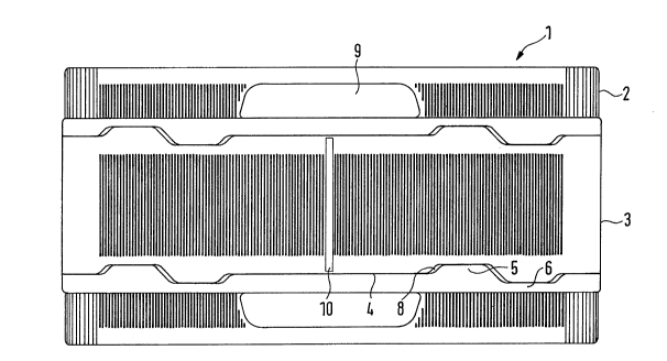
Fig. 2 presents a side view of a returnable container unit assembled
according to Fig. 1 of modular elements. The interface is here also
formed by pairwise arranged tongues 5 and grooves 6 with each two
tongues-grooves pairs 5, 6 for each narrow side~ The drawing,
moreover, shows that the tongues 5 as well as the grooves 6 are via
inclined faces set off the plane of the interface 4. The inclined face is
preferably provided with an angle of 30~. Depicted within the area of
the bottom/lid elements are, moreover, the recessed grips 9 which, in
this execution example, are formed as recesses, i.e. not open to the
inside of the con~ainer. Recognized in the middle of the collapsible
wall frame elements is also the hinge 10, being preferably formed as
film hinge.
Fig. 3 presents a side view of the inner wall of a wall frame element 3
being especially utilized for the length side of the wall frame. Fig. 3
shows clearly the wall frame element 3 on both of the narrow sides
with the articulated pin 11 for establishing a moveable connection with
the wall frame elements, especially the narrow sides of said elements.
Here, too, the tongues 5 and grooves 6 are arranged in pairs within
the area of the interface. Resorted to are preferably per interface two
pairs of tongues-grooves arranged in a row, i.e. tongues and grooves
are alternating. Fig. 3 shows, moreover, that the tongues 5 and
grooves 6 occupy with their width only a partial range of the
inteRacing edge, that is the outer edge of same. Recognized in this
picture are also the stiffening ribs envisaged especially for the inner
wall where they prevent a deformation of the wall frame elements and
ensure a reliable interaction of the interface with the complementary
interface of another modular element. For achieving this objective the
vertical stiffening elements are preferably aligned with the lateral ends
of the tongues and grooves resulting in increased stability in the area
of the interface configuration. The stiffening elements encompass
especially the longitudinal ribs 12 located on the edges as well as the
longitudinal ribs 12a being appointed parallelly at a spacing to the
longitudinal ribs 12. The longitudinal ribs 12 and 1 2a are in
connection with the cross ribs 13, located perpendicular to the
longitudinal ribs. Additional deflection ribs 1 3a are envisaged to
prevent goods becoming stuck on the longitudinal ribs 12 and 12a
during loading and packing. These deflecting ribs extend, as depicted,
from the longitudinal rib 12 on the edge via the longitudinal rib 12a to
the inside of the wall where they end in a pointed tip. These ribs, too,
are preferably located within the range of the interface configuration.
.
2136~3
Fig. 4 presents a partial view of the outside of the wall frame element
according to Fig. 3. Recognized apart form the tongues 5 and the
grooves 6, located on the outside edge of this element, is also the
depression 14 within the range of interface 1. This depression serving
as guide for the tensioning strap with which several of the modular
elements can be securely joined. The outside is, due to the ribs
formed on the inside, completely smooth thus offering an optimum on
advertising space.
Fig. 5 depicts the side view of the length side of a lid or bottom
element, respectively. This view showing distinctly the non-conical
shape of the corner regions 15.
Fig. 6 shows a side view of the narrow side of a lid respectively
bottom eiement 2 according to Fig. 5. Shown clearly, apart from the
already described shape of the interface, is once more the location of
the recessed grip 9.
Fig. 7 shows the layout of the snap-in hinge 11. For engaging the
hinge with the wall frame element 3 in an open condition, use is made
of a catch nose 16 located in the range of the hinge pin. The catch
nose being provided with a blind groove 17 located in the
corresponding hinge wing with which it interacts to a system by which,
in a tensioned condition, the catch nose 16 snaps into the blind
groove 17. The hinge wing formed by the wall frame elements will
thus collapse only i~ physical force is applied.
Fig. 8 finally shows a top view of a lid element 2. This view depicts
especially the non-conical shape of the corner region 15. Fig. 8 shows
clearly how the corner region 15 differs from the otherwise cone-
shaped side walls 16 of the modular elements 2. This arrangement
promotes a safe interstacking of the corner region 15 as the non-
conical shape of the corner region t 5 provides for an increased
contact area made available for load dissipation.
. .
.