Note: Descriptions are shown in the official language in which they were submitted.
pC.'TlFI93100217
~;v~,e0 93/2474;
1
Catalytic combustion engine exhaust gas purifier with
additional air supply M
The invention relates to a catalytic combustion
engine exhaust gas purifier with additional air supply,
comprising a housing structure accommodating an exhaust
gas inlet, at least one catalyst element, means for
laminarizing the exhaust gas flow, means for dividing
the housing structure into several chambers, an exhaust
gas out)_et and; additionally,, means for supplying addi-
tional air into: the exhaust gas flow in the housing
structure.
An exhaust gas purifier according to the pres
ent invention is used in connection with combustion
engines. The exhaust gas purifier of tha invention is
par icularly suitable for small two-stroke engines, such
as chain saws, lawn mowers; motor sledges, mopeds or
motor cycles, in which there is only a very small and
limited space for an exhaust gas purifier.
Catalytic exhaust gas purification is based on
the purification of the exhau t gas by feeding it
through one or more catalyst elements: The catalyst
elements contain a oatalytic agent which accelerates
the combustion of harmful impurities, i:e. in practice
it makes combustion- possible at a temperature lower than
normal : Today purification ~of exhaust gases is impor rant
especially for preventing environmental gallution. Con
ventiox~al catalyta.c purifiers have problems w~.th suffi
' ciency of Qxygen, because, if there is not enough oxy
gen, carbon anonoxide groduGed as a combustion product
of hydrocarbon is not further oxzdized into carbon di
oxide ~wing to the lack of oxygen. As carbon monoxide
his no smell and is colourless, it is hazardous to its .
environment and especially to people~ In order to im-
=35 prove the efficiency of batalytic purification it ~.s
'~iV~ 93/24?4~ . ~ ~ j ~ '~ ~ '~ PCT/FI93/00217<;: - .,
2
previously known to use exhaust gas purifiers into which
additional air is supplied from the outside, and 'thus
the oxygen contained in the additional air accelerates
the combustion reactions by means of which a faster and
more complete combustion of the principal pollutant
components of exhaust gas, i . e. carbon monoxide ( CO ) and
hydrocarbons (HC), is achieved. Catalytic exhaust gas
purifiers provided with additional air supply are called
oxidizing purifiers.
GB Patent 2 048 706 discloses a catalytic puri-
fier provided with additional air supply. In this con-
structinn additional air supply has bean improved so
that the tube supplying additional air extends inside
the purifier from one edge of the purifier to the other,
said tube comprising several holes for mixing the addi-
tional air with the exhaust gas: This construction does
not, however, enable a sufficiently good purification
result and; in addition, the air supply requires in this
case an external device such as a pump or a correspond-
ing device. DD Patent 31 11 498 discloses a so called
venturi-type additional air supply, in which a venturi
choking or reducing the exhaust gas flow and valves in
the additional air supply tube are used. for control-
l~ng the additional air flow. On account of the valves
this construction is more complex and hence more ex-
pensive and also'more usceptible to malfunctions be-
cause of its moving parts . Because of the choking ef fact
of the venturi, an exhaust gas, purifier of this kind
causes power losses and does not laminarize the exhaust ,
gas flow. The known solutions for additional air supply
are also sizable:
Tie object of the present invention is to pro-
vide a new type of exhaust gas purifier which avoids the
problems associatedwi~h the known solutions. y
X35 This object>is achieved with the exhaust gas
z136~35
~.V~ 93/2474; PC.°T/FI93/00217
3
purifier according to the invention, which is charac-
terized in that one or more suction plates are provided
in the chamber after the means laminarizing the exhaust
gas flow and at the same time in the vicinity of the
a means supplying additional air, that the suction plates
comprise exhaust gas ports, that the suction plates
comprise ports for the additional air, and that the suc-
tion plates are arranged against the exhaust gas flow
and the additional air flow so that the additional air
can be sucked through the ports and from the suction
plates into the actual exhaust gas flow passing through
the exhaust gas ports of the suction plates.
The exhaust gas purifier according to the in-
vention is based on the idea that the exhaust gas puri-
f~ex domprises means; i.e.-one or more suction plates
arrangad in the chamber, by means of which suction
plates' it is possible to - control the amount of addi-
tional air and-the opacity of-the exhaust gas flow to
suck addi Tonal fir,
Several advantages are achieved with the ex-
havst gas purifier according to the invention. By means
of the suction plates provided in the. chamber, effective
suction of additional air iota the exhaust gas flow is
achieved with a small construction. The construction
25 does not compx'ise any moving parts, wherefore the con-
struc ion ,is cheap to produce -and reliable in opera-
tion. Because of the effective suction of additional
air, the impurities in the. exhaust gas will axidize more
completely into carbon dioxide. In the solution accord-
30 ing to the invention the exhaust gas flow is not choked,
but the axhaust gas flow is laminarized, whereby the
angine does not suffer from power lossee: The use of the
suction plaices also e~rens out the pulsation of the ex
haust gases, whereby a reduced running noise level of
35 the engine is achieved.
3 JC . ... p~/~I93/00217y
~'~ 93/2474~i
4
The invention will be more closely described in
the follawing with reference to the accompanying draw-
ings, in which
Figure 1 is an internal schematic view of a
construction according to a first embodiment of the
exhaust gas purifier,
Figure 2a is a schematic view of a chamber
~l.ate,
Figures 2b-2d are schematic views of a suction
plate,
Figurs 3 is a cross-section at the arrows A-A
of Figure 1P
Figure 4 is a cross-section at the arrows B-B
of Figure 1,
~5 Figure. 5 is an internal schematic view of a
~anstruetion according to a second embodiment of the ex-
haust gas purl f ie.r;
Figure 6 is a Cross-section at the arrows C-C
of Figure 5,
Figure ? shows ~Che CO content vs. the number of
revolutions per minute w~.thout load,
Figure'8 shows the HC content vs. the number of
ze~ralutions per minute without load,
Figure 9 shows the HC content vs . -the number of
revolutions p~z' minute with full load,
Figure 10 shows the CO content vs: the number
of revolutions per minute with full load.
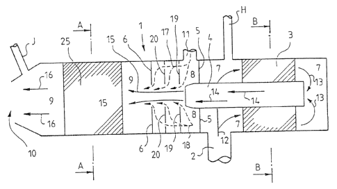
Figure 1 is a schematic view of the internal
construction of an exhaust gas purifier. The catalytic
o~hau~t gas purifier according to the invention cam-
prises a housing structure 1. The housing -structure 1
accommodates the follawing parts: an exhaust gas inlet
at least one catalyst element 5, means 4 such as a ,
tube for laminarizing 'the exhaust gas flow, means such
35 as chamk:r' plat~:s 5 and 6 for dividing the housing
21.36~~
PCTI FI93100217
~v'~ 93/24745
structure 1 into several chambers 7-9. Furthermore, in
the housing structure 1 are arranged, i.e. the~housing
structure l accommodates, an exhaust gas outlet 10 and
also means 1l such as an inlet for supplying additional
5 air into the housing structure 1, into the exhaust gas .
flow in at least one chamber. The exhaust gas flow is
indicated by the arrows 12-16 in various positions of
the exhaust gas .purifier. The additional air flow is
ihdicated by the arrows 17 and 1c3. The purpose of the
means 4, a:g. a tube, for laminarizing the exhaust gas
is to streamline he exhaust gas flow. According to the
invention one or more suction plates 19 , 20 are arranged
in the chamber 8'after the means 4 laminarizing the ex-
haust gas flow l.4 and a't the same time in the vicinity
1S of the means 1l supplying additional air. Figure 1 shows
two successive suction plates, i.e. suction plates 19
and 20, after which the exhaust gas purifier comprises
a hermetically attached, e.g. welded, second chamber
plate 6 . In , the housing str ucture 1 the f first chamber
plate 5 is arranged ups-~r~am of the additional air inlet
11, i.e. around the means 4; preferably a tube; for lam-
inarizing 'the exk~aust gas f~,oca~ Figures 2b and 2c show
the suction plates 19 and 20 shown also in Figure 1:
With reference to Figures 1;. ~b and 2c the suction
plates 19' and 20; according to the z:nyention; further
comprise exhaust gas ports 21a and 2lbo The second sham-
ber plate 6 shown in Figuxe. 2a comprises an exhaust gas
port 21c. The exhaust gas ports 21a-21c-shown in Figures
2a-2c are provided at the arrows 15 indicating the ex-
haust gas f~.c~w in Figure I. Furthermore, according to
he invention, the suction plates 19 and 20 comprise
parts 22a-22d for additional air and, additionally,
according to the invdntion, the suction plates 19 and
20 are arranged against the exhaust gas flow l4, 15 and
' the additional air flow 17 and 18 so that the additional
PCT/FI93/00217
~V~ 9312474
6
air can be sucked through the ports 22a-22d and through
the suction plates 19 and 20 into the actual exhaust gas
flow 15. The additional air ports 22a-22d in the suction
plates 19 and 20 as shoran in Figures 2b and 2c are pro-
vided in Figure 1 at the points where the arrows 17 and
18 indicating the additional air flow penetrate the
suction plates l9 and 20. The exhaust gas ports 21a and
21b do nat necessarily have to be positioned in the suc-
tion plates 19 and 20 as shown in Figures Zb and 2c.
Alternatively, the exhaust gas ports 21a and 21b can
be openings between the actual suction plates 19 and 20
and the housing structure l and, likewise, the addi-
tional air ports 22a-22d can also be openings between
the, actual suction plates 19 arid 20 and the housing
struc'cure 1. These alternative embodiments should, how-
ever, be seen as a construction embraced by the pres-
ent invention, because it is essential for the opera-
tion of the ports that the exhaust gas and the addi-
ianal air can be supplied v'ia the ports either through
the suct~.on plate or Bast it. As regards the existence
of the por s, the essential fact is that the ports are
areas removed from the suction plates 19 and 20, such
as holes aGCOrding to Figures 2b-2d ar; alternatively,
the suction plates 19 and ~0 have a broken edge, in
which case the ports are formed between the actual suc-
tion plate 19 and 20 and the housing structure 1 or some
other structure:
In a preferred embodiment of the invention in
accordance with Figures'2b-2c the additional air ports
22a~22b in the suction plate 19 and the additional a:ir
ports 22c~22d in the suction plate 20 are arranged
around the exhaust gas gores 21a and 21b, respectively.
In this case it is possible to guide the: additional air
symmetrically around the exhaust gas ports 21a and 21b
provided closer to the centre of the suction plate, and
~~~s~3~
.rVO 93/2474x , a - ' PCT/FI93/00217
7
thus the exhaust gas flow can more effectively suck the
additional air with it. ..
In a preferred embodiment of the invention with
reference to Figures 2b-2c the additional air ports of
the successive suction plates 19 and 20 in Figure 1 are
provided at dissimilar positions in the flow direction,
i~e. not in lime: This means that the additional air
ports 22c,and 22d of the second suction plate 20 do not
follow directly after the additional air ports 22a and
22b of the first suction plate 19. This also improves
the capacity of the suction plates 19 and 20 to pre-
vent the harmful back flow, because the back flow cannot
move direr 1y backwards.
In a preferred embodiment of the invention the
size of the exhaust gas ports 21a and 21b of the suction
plates l9 and 20 is chosen so that the size of the ports
increases in the flow direction; i.e. the port 21b of
the second suct~.on plate 20.is larger than the port 21a
of the first suction plate 19, because with an increas
ing number of suction plates the amount of air in-
creases, and thus it is easier to include the increasing
amount of air in the exhaust gas ports 21a and 21b. As
stated above; the second chamber plate 6 positioned
alter the last actual suction plate 20 and shown in
Figures 1 and 2a is also preferably uch that the ex-
haustgas port 21c contained in it is 2arger than the
ports in 'the suction plates 19 and 20 posit~.oned before
the chamber plate. The applicants have found that a
suitable way of dimensianing the exhaust gas ports 21a-
21c is such that the size. of the exhaust gas ports 21x-
21c increases from the 20 millimetres of the suction
p~:ate 19 with an increment of. one mi~.lametre to the 22
millimetres of the second chamber plate 6. In Figures
2a-2c the size or diameter of-the ports is indicated by
'35 the arrows i7, E and Fof which D is the shortest, i.e.
P~'f/F1~3/00217' .~
2Z3~~3~ ''v
wo 9~/z47~s -
s
20 mm, and F the longest, i.e. 22 mm.
According to a preferred embodiment of the in-
vention the suction plate 23 shown in Figure 2d is such
that the part of the suction plate 23 has.a configura-
tion 2~ increa'sing the length of the edge of the port
21d. It can be seen from Figure 2d that the uneven edge
configuration provides considerably more edge length
than the round edge shown in Figures 2b-2c. By length-
ening the edge of the exhaust gas port 21d of the suc-
Lion prate 23 the suction of the additional air into the
exhaust gas f low 15 is improved, because in practice the
suction plate then has more edge length at which the
additional air leaves the suction plate and is sucked
into the exhaust gas flow.
~,5 Figure 4 shows a cross-section of the housing
s ructure 1 at the arrows B-B of Figure 1. Figure 4
shows more clearly one preferred embodiment for posi-
tioning the means ~ laminarizing the exhaust gas flaw.
Iri Figures-1 and 4 the means for laminarizing the ex-
2p haust gas flaw is arranged inside a first catalyst ele-
merit, i . a . in practa.ce the catalyst element 3 is arrang-
ed around-the tube 4. This construction increases the
likelihood of achieving a small exhaust gas purifier.
With x'eference to Figure 1 the housing struc
25 Lure 1 is divided by means of chamber plates into sev
eral chambers so that the chamber plates 5 and 6 divide
the housing structure at least into three chambers 7
9: ~'he-first chamber plate 5 and the housing structure
define a first chamber 7, which is a chamber into which
30 the exhaust gas is supplied from an exhaust gas inlet.
A second chamber 8 is a space defined by the hauszng
structure and the first chamber plate 5 and the second
chamber plate 6. The second chamber g is specifically
the chamber into which-the means; such as a tube ~, for
'35 laminarizing the exhaust gas flow direcas the exhaust
PCT/Fi93/00217
v d'VO 93/2474; ~ ~ ~ ~ ~ ~ ~ . .
9
gas flow 14. Additional air supply is also provided in
this second chamber 8 and, moreover, the suction'plates
19 and 20 are also arranged in the same chamber. A third
chamber 9 is provided by a space between the second
chamber plate 6 and the housing structure. An essential
feature of the invention is to arrange one or more suc-
tion plates against the flow of exhaust gas and addi-
tional air iz~ the brief space of the chamber 8 after
the means 4 laminarizing the exhaust gas flow.
1p ' The points indicated by the reference numeral
50 in Figures 2a-2d are spot caelds by means of which
-the suction plates and chamber plates can be attached
to the housing structure.
Figure 3 illustrates a cross-section at the
arrows A-A in Figure 1. With reference to Figures 1 and
3 a second catalyst element 25 is arranged in the third
chamber 9 of the housing srruc::ure 1. The object of the
preseazt inven Lion mainly relates to mechanical imple
men-tation of an exhaust gas purifier and not primarily
20- to ca alyst elements and chemical reactions occurring
in them. On account of the above it is briefly stated
that the catalyst elements ~ and 25 are of a type known
per se; i.e. catalyst cells which comprise for example
a ceramic or metallic support cell structure and an
intermediate layer-provided thereon and comprising ac-
celerators for chemical reactions. For example an inter-
mediate layer of aluminium oxide is coated with a mix-
Lure of precious meals, e.g. a mixtuxe of platinum and
rhodium. Irl the first ctaamber 7 containing the first
3p catalyst 3, the hydrocarbons (HC) are oxidized into
carbon dioxide (C02), carbon monoxide (CO) and water
(H20); if there ie not enough oxygen present. Thus the
exhaust gas will contain harmful carbon monoxide (CO).
In the following the operation of the exhaust
' 35 gas purifier of the invention will be described with
V!'O 93/2474a ~ ~ ~ ~ ' . . , , P(.'T/FI93/I)I)217 t- r.
reference to Figures 1 to 4. The exhaust gas i~ supplied
from the engine ( not shown ) through the exhaust gas
in~.et 2 into the first chamber 7 in the housing struc-
ture 1. The exhaust gas flow 12 passes through the first
5 catalyst element 3, after which the exhaust gas flow 13
is diverted at the end of the chamber 7 into the tube
~ laminarizing the exhaust gas flow. While passing
through the tube 4 the exhaust gas flow 14 is lamina-
rized. The tube 4 directs the laminar exhaust gas flow
10 into the second chamber 8 in which the suction plates
19 and 20 are arranged. The simplest means for supplying
additional air is an additional air inlet 11 arranged
in conneuLion cYith the second chamber 8. The suction
plates 19 and 20 are arranged in the vicinity of both
1~ the additional air' supplying means 11 and the means,
i.e. the tube 4, far laminarizing the exhaust gas. The
additional air'8ow 17 and 18 passes to the first suc-
tion place 19 and penetrates it through the additional
air; inlets 22a and 22b provided in the suction plate 19;
arid thus the additional air enters the area between' the
first suction plate 19 and the second suction plate 20:
Part of the additional air flow 17 and 18 is -sucked from
the edge of the exhaust gas port 21a ofythe first suc-
tion plate 7.9 cai th the pulsation of the laminar exhaus t
gas flow 15. The exhaust gas flow is directed by means
of the tube laminarizing the ez~haust gas flow ~o the
exhaust gas port 21a positioned in the middle of the
first suction plate 19. Part of the additional air flow
17 and 18 passe forwards in the longitudinal direction
of the'housing structure ~ and penetrates the second
suction plate 20 through the additional air ports 22c
and 22d, and thus the additional air flow passes between
the second suction plate 20 and the second chamber plate
6, wherefrom the additional air is sucked with the pul-
~5 ration of the exhaust has flow 15. Thereafter the ex-
,..
,y~ 93/274; PCT/F793/00277
11
haust gas flow containing additional air passes to the
third chamber 9 in which a second catalyst cell 25 is
arranged. In the third chamber 9 the carbon monoxide
l, CO ) still remaining in the exhaust gas is oxidized into
carbon dioxide on account of the additional oxygen from
the additional air,. In a preferred embodiment of the
invention the second catalyst element 25 is positioned
at a suitable distance from the second chamber plate 6
in order for the exhaust gas flow to be able to spread
all aver the cross-sectional area of the catalyst ele-
ment 25. The purified exhaust gas flow 16 is removed
from the housing structure through an outlet 10. The
e::haust gas IS exhibits a sinusoidal pulsation in con-
formity with the running of the combustion engine. The
applicants have found that the suction plate - chamber
construction according to the invention enables the
addivtional air to effectively fill the low-amplitude
portions of the pulsation of the exhaust gas.
Figure 5 is an internal schematic view of a
construction according to a second embodiment.of the
exhaust gas purifier, the major difference to the solu
Lion according to Figure 1 being the manner of supplying
the additional aiz to the suction plates. The construc
tion and operation shown in Figure 5 are in principle
nearly similar to those in the embodiment of Figure 1,
and in this connection reference is made tp the above-
described constructipn and operational principle. As
shown in Figure 5~ the exhaust gas purifier according
' to the second embodiment comprises a housing structure
101 accommodating an exhaust gas inlet 102, at least one
catalyst element 103; means 104 for laminarizing the
exhaust gas flow, me~.ns 105 and 106, such as chamber
p7:ates, for dividing the housing s~tructu~ce into sevaral
cambers 108-109, an exhaust gas outlet 110 and, addi
'35 tionally, means 111 for supplying additional air into
.. ..: ::. . , .
W~ 93/2474 PL T/FI93/002I ? ~ . ..
12
the exhaust gas flow in the housing structure, which
last-mentioned means in this preferred embodiment of the
invention is a means 111 supplying additional air and
being a flow space provided at the surface area of the
housing structure. The flow space 111 extends advant-
ageously over a considerable part of the surface area
of the housing structure 101 and advantageously in such
a way than the flow space 111 surrounds a considerable
part of the housing structure, and preferably in accord-
ante with Figures 5 and 6 so that the flow space 111
is arranged at the surface area of the housing structure
so that it essentially surrounds the whole housing
structure. This construction enables the additional air
to be used for cooling the housing structure 101. Figure
6 shows a tube 1.04 intended for laminarizing the exhaus t
gad flow, a catalyst element 103 arranged around it, and
a flow space 111 between the catalyst element 103 and
the housing structure 10l, which flow space provides a
means for supplying additional air.
As in'Figure 1, the exhaust gas purifier ac-
cording to Figure 5 also comprises similar structures
with the except~:on that there are three suction plates;
i : e. suction plates 119, 120 and 12l . The suction plates
and the second chamber plate 106 comprise exhaust gas
ports, which are positioned at the arrow 215 indicating
the exhaust gaa flow. The suction plates 119'-121 also
comprise additional air ports; which are positioned at
the arrows 130 and 131: The second chamber plate 106
also comprises ari exhaust gas port 121c. Corresponding
1~, a -second catalyst -element 125 is, axra.nged in the
third chamber 10~ . The esseno2 of Figures 5 and 6 is;
however, the structure by means of which the additional
air flow 117 arid 118 is brought through the elongated
flow space 111 to the suction plates 119-121 in the lon
gitudinal direction of the housing structure 101.
CA 02136535 2003-08-11
- 13 -
FIGS. 7-9 show test results on the efficiency of
purification of the exhaust gas purifier according to the
invention measured on a two-stroke lawn mower. In all FIGS.
7-9 the uppermost graph represents the exhaust gas from the
engine, measured at the measuring point H shown in FIG. 1.
In all FIGS. 7-9 the middle graph represents the purified
exhaust gas, measured at the measuring point J shown in FIG.
1, but with no supply of additional air. In all FIGS. 7-9
the lowermost graph represents the purified exhaust gas,
to measured at the measuring point J shown in FIG. 1, but with
supply of additional air into the exhaust gas.
FIG. 7 shows the CO content measured without load
vs. the number of revolutions per minute (rpm) of the
engine. It can be seen from FIG. 7 that the CO content, i.e.
the carbon monoxide content, decreases to one fourth in the
presence of additional air supply as compared with the case
of no additional air supply.
FIG. 8 shows the hydrocarbon (HC) content measured
without load on a ppm scale vs. the number of revolutions
2o per minute (rpm) of the engine. It can be seen from FIG. 8
that the HC content decreases to less than half in the
presence of additional air supply as compared with the case
of no additional air supply.
FIG. 9 shows the hydrocarbon (HC) content measured
with load on a ppm scale vs . the number of revolutions per
minute (rpm) of the engine. It can be seen from FIG. 9 that
the HC content decreases to less than one third in the
presence of additional air supply as compared with the case
of no additional air supply.
3o FIG. 10 shows the carbon monoxide content vs.
the number of revolutions per minute measured with
full load. In FIG. 10 at the high number of revolutions
per minute, i.e. of the order in excess of 2600 rpm,
the uppermost graph represents the exhaust gas from the en-
PCT/F193/0021 ; ~: : .
WO 93/2474
14
gines, measured at the measuring point H shown in Figure
1. The middle and lowermost graphs represent the..puri-
fled exhaust gas, measured at the measuring point J
shown in Figure 1. The middle graph represents the case
with no.additional air supply and the lowermost graph
the case of additional air supply. Figure 10 shows how
the additional air supply decreases the carbon monoxide
content, especially at high numbers of revolutions per
minute, i.e. of the order of 000 rpm: It should be
noted that small engines are often used at almost maxi-
mum speed of rotation.
Although the invention has been described above
with reference to the examples according to the accom-
panying drawings; it is clear that the invention is not
limited to them, but it can be varied in many ways with-
in the scope of the inventive idea disclosed in the
enclosed claims.