Language selection

Search

Patent 2136562 Summary

Third-party information liability

Some of the information on this Web page has been provided by external sources. The Government of Canada is not responsible for the accuracy, reliability or currency of the information supplied by external sources. Users wishing to rely upon this information should consult directly with the source of the information. Content provided by external sources is not subject to official languages, privacy and accessibility requirements.

Claims and Abstract availability

Any discrepancies in the text and image of the Claims and Abstract are due to differing posting times. Text of the Claims and Abstract are posted:

  • At the time the application is open to public inspection;
  • At the time of issue of the patent (grant).
(12) Patent: (11) CA 2136562
(54) English Title: CIRCUIT FOR SENSING TELEPHONE LINE CONDITIONS
(54) French Title: CIRCUIT POUR DETERMINER LA CONDITION DES LIGNES TELEPHONIQUES
Status: Deemed expired
Bibliographic Data
(51) International Patent Classification (IPC):
  • H04M 1/72 (2006.01)
  • H04M 1/82 (2006.01)
(72) Inventors :
  • KURDZIEL, RYSZARD (Canada)
(73) Owners :
  • NORTEL NETWORKS LIMITED (Canada)
(71) Applicants :
  • KURDZIEL, RYSZARD (Canada)
(74) Agent: BORDEN LADNER GERVAIS LLP
(74) Associate agent:
(45) Issued: 2002-02-05
(22) Filed Date: 1994-11-24
(41) Open to Public Inspection: 1995-07-01
Examination requested: 1998-11-23
Availability of licence: N/A
(25) Language of filing: English

Patent Cooperation Treaty (PCT): No

(30) Application Priority Data:
Application No. Country/Territory Date
5-349935/93 Japan 1993-12-30

Abstracts

English Abstract


A circuit for sensing telephone line conditions,
comprising: high impedance termination means across the
telephone line; means for accumulating charge through
said high impedance termination means; and electrical
isolator means intermediate said means for accumulating
charge and voltage detecting means.


Claims

Note: Claims are shown in the official language in which they were submitted.


CLAIMS:
1. A circuit for sensing telephone line conditions, comprising:
high impedance termination means across the telephone line;
means for accumulating charge through said high impedance
termination means;
electrical isolator means intermediate said means for accumulating
charge and voltage detecting means;
said means for accumulating charge is strobed periodically by
means of optical coupler to transfer its charge to said electrical
isolator means; and
said means for accumulating charge is a capacitor connected in
series with a variable resistance when said telephone line is not
terminated by an off-hook condition, and said capacitor is connected in
parallel with a high resistance of several million ohms.
2. A circuit for sensing telephone line conditions, comprising:
high impedance termination means across the telephone line;
means for accumulating charge through said high impedance
termination means;
electrical isolator means intermediate said means for accumulating
charge and voltage detecting means; and
electrical isolator means is a transformer; and
said transformer has a diode connected in series with its
secondary winding for charging a capacitor in proportion to accumulated
charge on said means for accumulating charge when the later is strobed
to discharge it through a primary winding of said transformer.


3. The circuit as defined in claim 2 wherein said capacitor has its
state of charge periodically sensed by an analog-digital convertor.
4. The circuit as defined in claim 3 wherein said means for
accumulating charge is another capacitor on one side of a rectifier, the
other side of which is connected to the telephone line.

Description

Note: Descriptions are shown in the official language in which they were submitted.


~i~~~i~2
-- 1
A CIRCUIT FOR SENSING TELEPHONE LINE CONDITIONS
BACKGROUND OF THE IVVENTI0~1
1. Field of the Invention
The present invention relates to telephone sets in
general, and in particular to a circuit in a telephone
set for sensing the condition of a telephone line to
indicate, for example, whether another telephone or
other device on the line, or one of a number of lines,
is off-hook. Other conditions of a line may also be
sensed, such as "Message Waiting".
2. Prior Art of the Invention
United States patent 4,647,723 granted March 3, 1987 to
K.R. Voorhies discloses a solid state circuit designed
to be incorporated into a telephone terminal instrument
to prow de a W sual indication at that instrument that a
i
telephone line to which the instrument is connected is
already in use by another telephone instrument.


2
SUMMARY OF THE INVENTION
The object of the present invention is to provide a line
condition sensing circuit suitable for microcomputer
controlled telephone sets and the like.
The circuit of the present invention provides electrical
isolation between the telephone set it is incorporated
in and the telephone line it is monitoring; this
provides electrical isolation between different lines
connected to the same telephone set.
In addition to sensing that another telephone set or
device is using the line it is connected to, the circuit
may also be used to trip an answering machine, to log
calls as answered in a call display telephone, to
automatically drop a held call, to indicate
disconnection of the telephone cord, or to indicate a
"message waiting" signal on the monitored line.
Accordingly, the present invention provides a circuit
for sensing telephone line conditions, comprising: high
impedance termination means across the telephone line;
i
means for accumulating charge through said high
impedance termination means; and electrical isolator
means intermediate said means for accumulating charge


3
and voltage detecting means.
BRIEF DESCRIPTION OF THE DRAWINGS
The preferred embodiment of the present invention will
now be described in conjunction with the annexed drawing
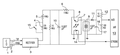
figure, which is a circuit and black schematic for use
in a multi-line telephone set.
DETAILED DESCRIPTION OF THE PREFERRED EMBODIMENT
Referring now to the drawing figure, a central office
(CO) 1 is connected via telephone line 2 to voltage
rectifier 3, the output of which is connected through
high impedance resistor 4, resistor S and resistor 6 to
phototransistor 7 in optical coupler 8 (also known as
optical insulator), the other terminal of which is
connected to one end of the primary winding of
electrical isolator (a pulse transformer) 9, the other
end of the primary winding completing the circuit by
being connected to the remaining terminal of the
rectifier 3, to which is also connected one terminal of
charge accumulating capacitor 10, the other terminal of
i
which is connected to the phototransistor end of the
resistor 5. This is the "CO side" of the circuit of the
present invention, which CO side is electrically


_ 4
isolated from the telephone set side by means of the
electrical isolating pulse transformer 9.
The secondary winding of the transformer 9, is connected
via rectifier diode 11 and resistor 12 to the A/D
(analog-to-digital) input of a micro-corputer 13 in the
telephone set. A capacitor 14 is connected between the
cathode of the diode 11 and the other terminal of the
secondary winding of the transfor::ler 9. The
microcomputer 13 "strobes" light emitting diode 14 in
the optical computer 8 when required, thereby
discharging the capacitor 10 via the resistor 6 through
the primary winding of the transformer 9. This side of
the circuit shown is the "local side".
In operation; when hook-switch contact 15 (across the
resistor 4) is open (that is in the off-hook condition),
the diode 11 ensures that the voltage at the A/D input
of the microprocessor 13 is always above ground
reference. Resistor 12 and 16 bleed capacitor 17, so
that its voltage follows the voltage across the
telephone line 2. Since the line 2 "sees" a very high
impedance of approximately 21M ohm across, it is
unaffected, and several such impedances may be across
the same line in parallel without violating the on-hook
impedance specifications of the telephone company.


2~~~5~2
_ 5
Also, in this condition the high voltage dividing ratio
permits voltage sensing up to 120 volts. (Thus enabling
the microprocessor 13 to recognise a "message waiting"
voltage on the telephone line 2).
In an off-hook condition of the telephone set the switch
15 is closed. The impedance then seen by the line 2 is
approximately 1M ohm. Voltages up to approximately 12V
can be measured. The lower ratio of the voltage divider
yields better resolution for the low voltages present
while off-hook.
Timing control of the circuit is provided by the
microprocessor 13. The microprocessor 13, having an
analog to digital convertor, uses it to measure the
voltage developed on the local capacitor 17. The
microprocessor 13 uses the voltage measurements to
indicate that the extension is in use, and so forth.
The microprocessor 13 uses a slower strobe or sample
rate for on-hook conditions than it does for off-hook
conditions. This is done in order to minimize the risk
of violating the on-hook impedance specifications. The
i
on-hook sample period is 160 ms. The off-hook sample
rate is 16 ms.


213~5~~
6
The microprocessor 13 operates (strobes) the LED 14
whenever a sample is required. The optically coupled
transistor 7 switches the charge from the capacitor 10
through the pulse transformer 9 to the capacitor 17.
The microprocessor 13 then measures the voltage on the
capacitor 17 within a certain time limit to guarantee a
certain precision of measurement as required.
Representative Drawing
A single figure which represents the drawing illustrating the invention.
Administrative Status

For a clearer understanding of the status of the application/patent presented on this page, the site Disclaimer , as well as the definitions for Patent , Administrative Status , Maintenance Fee  and Payment History  should be consulted.

Administrative Status

Title Date
Forecasted Issue Date 2002-02-05
(22) Filed 1994-11-24
(41) Open to Public Inspection 1995-07-01
Examination Requested 1998-11-23
(45) Issued 2002-02-05
Deemed Expired 2005-11-24

Abandonment History

There is no abandonment history.

Payment History

Fee Type Anniversary Year Due Date Amount Paid Paid Date
Application Fee $0.00 1994-11-24
Registration of a document - section 124 $0.00 1996-11-07
Maintenance Fee - Application - New Act 2 1996-11-25 $100.00 1996-11-14
Maintenance Fee - Application - New Act 3 1997-11-24 $100.00 1997-11-19
Request for Examination $400.00 1998-11-23
Maintenance Fee - Application - New Act 4 1998-11-24 $100.00 1998-11-23
Maintenance Fee - Application - New Act 5 1999-11-24 $150.00 1999-11-22
Registration of a document - section 124 $0.00 2000-02-07
Maintenance Fee - Application - New Act 6 2000-11-24 $150.00 2000-11-24
Final Fee $300.00 2001-09-21
Maintenance Fee - Application - New Act 7 2001-11-26 $150.00 2001-11-19
Maintenance Fee - Patent - New Act 8 2002-11-25 $150.00 2002-10-29
Registration of a document - section 124 $0.00 2002-10-30
Maintenance Fee - Patent - New Act 9 2003-11-24 $150.00 2003-10-22
Owners on Record

Note: Records showing the ownership history in alphabetical order.

Current Owners on Record
NORTEL NETWORKS LIMITED
Past Owners on Record
KURDZIEL, RYSZARD
NORTEL NETWORKS CORPORATION
NORTHERN TELECOM LIMITED
Past Owners that do not appear in the "Owners on Record" listing will appear in other documentation within the application.
Documents

To view selected files, please enter reCAPTCHA code :


To view images, click a link in the Document Description column. To download the documents, select one or more checkboxes in the first column and then click the "Download Selected in PDF format (Zip Archive)" or the "Download Selected as Single PDF" button.

List of published and non-published patent-specific documents on the CPD .

If you have any difficulty accessing content, you can call the Client Service Centre at 1-866-997-1936 or send them an e-mail at CIPO Client Service Centre.


Document
Description 
Date
(yyyy-mm-dd) 
Number of pages   Size of Image (KB) 
Drawings 2001-09-21 1 14
Cover Page 2002-01-08 1 31
Claims 1999-02-15 2 46
Cover Page 1995-08-22 1 15
Abstract 1995-07-01 1 9
Description 1995-07-01 6 134
Claims 1995-07-01 1 9
Drawings 1995-07-01 1 17
Representative Drawing 2002-01-07 1 7
Fees 1999-11-22 1 27
Fees 2000-11-24 1 28
Fees 2002-10-29 1 32
Fees 1998-11-23 1 29
Assignment 2000-01-26 43 4,789
Assignment 2000-09-25 29 1,255
Correspondence 2000-02-08 1 16
Correspondence 2000-02-08 1 22
Correspondence 2000-12-01 1 21
Assignment 1994-11-24 10 384
Prosecution-Amendment 1998-11-23 8 237
Prosecution-Amendment 2001-09-21 2 41
Correspondence 2001-09-21 1 26
Prosecution-Amendment 2001-10-01 1 15
Fees 1997-11-19 1 35
Correspondence 2005-01-19 2 158
Fees 1996-11-14 1 34