Language selection

Search

Patent 2137006 Summary

Third-party information liability

Some of the information on this Web page has been provided by external sources. The Government of Canada is not responsible for the accuracy, reliability or currency of the information supplied by external sources. Users wishing to rely upon this information should consult directly with the source of the information. Content provided by external sources is not subject to official languages, privacy and accessibility requirements.

Claims and Abstract availability

Any discrepancies in the text and image of the Claims and Abstract are due to differing posting times. Text of the Claims and Abstract are posted:

  • At the time the application is open to public inspection;
  • At the time of issue of the patent (grant).
(12) Patent Application: (11) CA 2137006
(54) English Title: PORTABLE AIR CONDITIONER
(54) French Title: CONDITIONNEUR D'AIR PORTATIF
Status: Dead
Bibliographic Data
(51) International Patent Classification (IPC):
  • A61M 15/02 (2006.01)
  • A61F 7/00 (2006.01)
  • A62B 7/00 (2006.01)
  • A62B 9/00 (2006.01)
  • A62B 18/00 (2006.01)
  • F24F 3/16 (2006.01)
(72) Inventors :
  • HANSEN, IVER (Norway)
(73) Owners :
  • HANSEN, IVER (Norway)
(71) Applicants :
(74) Agent:
(74) Associate agent:
(45) Issued:
(86) PCT Filing Date: 1993-06-01
(87) Open to Public Inspection: 1993-12-09
Examination requested: 1994-11-29
Availability of licence: N/A
(25) Language of filing: English

Patent Cooperation Treaty (PCT): Yes
(86) PCT Filing Number: PCT/NO1993/000088
(87) International Publication Number: WO1993/024168
(85) National Entry: 1994-11-29

(30) Application Priority Data:
Application No. Country/Territory Date
921853 Norway 1992-06-01

Abstracts

English Abstract

2137006 9324168 PCTABS00028
A personal portable air conditioner or air purifier with a
carrying arrangement, which includes a neck strap (11), delivers
conditioned or purified air to the head/facial area of the user. The
apparatus consists of a filter/fan unit (8, 2), arranged to direct
a concentrated flow of conditioned or purified air toward the
user's mouth and nose. The filter/fan unit may also be kept secure
in its position by a lower belt (fig. 4) which is included in the
carrying arrangement, or for instance by using braces or a tight
fitting pocket in a useful position. The filter/fan unit is also
equipped with a rapid fastening arrangement, for instance a
VelcroR attachment (20), for one or several additional accessories
for air regulation included as optional parts of the apparatus.


Claims

Note: Claims are shown in the official language in which they were submitted.


PCT/??93/00089

C L A I M S

1. A personal portable air purifying apparatus with a carrying arrangement, e.g. including a
neck strap (11), for delivery of purified air to the users head/facial area,
c h a r a c t e r i z e d in that it comprises a filter/fan unit (8,2), affixed to the chest of the user,
said unit adapted to direct a concentrated stream of purified or conditioned air toward the user's
mouth and nose.

2. Apparatus according to claim 1,
c h a r a c t e r i z e d in that said filter/fan unit may also be kept in a stable and secure position
by a lower belt (fig. 4) included in the carrying arrangement, or for instance by the use of straps
or a tight fitting pocket or pouch in a suitable position.

3. Apparatus according to claim 1 or 2,
c h a r a c t e r i z e d in that said filter/fan unit is equipped with a rapid fastening arrangement,
for instance a Velcro attachment (20), for one or several further air influencing units to be
included as optional parts of the apparatus.

4. Apparatus according to claim 3,
c h a r a c t e r i z e d in that said further air influencing units comprise an ionizing unit (fig. 3
and fig. 8), an air cooling/humidifying unit (fig. 2 and fig. 7) and air current steering devices
(14A, 14B, 50-58, fig 5, fig. 6, 64).

5. Apparatus according to claim 4
c h a r a c t e r i z e d in that said air current steering devices include an electronic control
means (50-58), comprising detectors (52,53) for head movement of the user and controllable
devices (51,56,57,58) in or by an air outlet orifice for changing air fanning direction.

6. Apparatus according to claim 4,
c h a r a c t e r i z e d in that the air current steering devices include a manually adjustable
contraption for channeling a flow of air towards the desired area, for instance a manually
adjustable directing fin (fig. 6, 64) or swan's neck (fig. 5) of a flexible type, both having a base
attachable at the top of the apparatus by the use of a Velcro attachment (20), a magnet
attachment, or other rapid fastening arrangements.

7. Apparatus according to claim 4,
c h a r a c t e r i z e d in that the air current steering devices include a flexible and elastic air
duct (59), attached by means of a quick fastening arrangement, for instance a Velcro

WO 93/24168 PCT/NO93/00086

attachment (20), to the filter/fan unit (fig. 1 and 60), and a mask which covers the nose and
mouth (fig. 12), optionally also the eyes (fig. 13).

8. Apparatus according to one of the preceding claims,
c h a r a c t e r i z e d in that it includes a housing with an adjustable sloping rear hatch (fig.
1,13), adaptable to the users chest angle and posture, by e.g. an adjustment screw (14A),
notches or tooth edged adjustment pin (14B) arranged at the top or bottom of the apparatus for
adjustment of the angle of the rear hatch.

9. Apparatus according to one of claims 4-8,
c h a r a c t e r i z e d in that the ionizing unit (fig. 3) ionizes the departing air of the apparatus
and is easily attachable as a front part of the apparatus by means of a Velcro attachment (20),
magnet attachment, or another rapid fastening arrangement, by which the ionizing unit (fig. 3) is
placed as far away from the user's body as practically possible, optionally, by having a smaller
ionizing unit (fig. 8) influencing the air and being correspondingly attachable as a top part of the
apparatus, and that the ionizing units (fig. 3 and fig. 8) are adjustable (17) regarding the amount
of ionization, and optionally, directional adjustment of outgoing ions (18).

10. Apparatus according to one of claims 4-9,
c h a r a c t e r i z e d in that the cooling/humidifying unit (fig. 2 and fig. 7) includes a
thermoelectric cooling unit which can be fastened to the filter/fan unit by a Velcro attachment
(20), magnets or other quick fastening arrangement.

11. Apparatus according to one of claims 4-9,
c h a r a c t e r i z e d in that the cooling/humidifying unit (fig. 2 and fig. 7) comprises a cooling
means based on refrigerated material, for instance ice, dry ice or the like.

12. Apparatus according to claim 11,
c h a r a c t e r i z e d in that the cooling/humidifying unit (fig. 2) consists of an outside insulated
covering case (61), the interior cooling sheath (62) of the covering case having a shape
adapted to the exterior shape of the filter/fan unit or, optionally to the exterior shape of the
filter/fan unit when said further air influencing unit is attached thereto.

13. Apparatus according to one of claims 4-12,
c h a r a c t e r i z e d in that said filter/fan unit (fig. 1) includes a filter (8), optionally consisting
of several partial filters of various types arranged in series, close to an air inlet (63), and a fan
(2) which may be of a centrifugal or propeller type.


Description

Note: Descriptions are shown in the official language in which they were submitted.


wo 93/24168 2~ P~/N093/000B~


PORTA8LE AIR Ct)Nl~lTlONER

This invention is a portable air conditioning or air purifying unit for persons with health problems
due to air quality. These healUl problems include h~adache, fatigue, depressions, etc. and po~sibiy
sorne types of aller~ic an~ asthmatic reactions as weli. .

To imptove air quality there are many d~rices availab3e. How~ver, most have the cornmon
di~advanta~e ~f purffyin~ air only ~n the immediate surroundings without always securin~ suFficient
~cation and i nprovement of air ctosest to tha u~rs head~faaat and breathing ~rea.

Even when usin~ expensive st~tionary air ~nditionsrs and purification equipment, users may still
breathe polluted and noxious air wh~n for instance ci~aretta smoke comes betw~n tha ussr and
~e ~ir puri~ying unit.

Having soma heal~h problems due to air pollution, ~he inventor has been experimenting since 1977
making both stationary and portable air purif~ers. He carne to ~e conclusion tha~ he benefited most
wh~n using an air puri~ler close to his breathing or~ns. There~ore, he made air purifiers smaller
and port~bl~, bec~use other purifiers on tl~ market wer~ stationary and consequantly did not ~olYe
the health probbms mentioned above.

In a German publication, DE 27 33 729 Ei 2, a stationary air purifier with a combination of ioniz~r
and ~an has b~n presented earlier. This purifi~r does not solve the above mentioned problems as
it i5 stationary.

Th~ inventor designed several small ~ir puriffers which are portable and use a neck ~rap. He also
designed portable ionkers havin~ certain similar ~eatures as ~ose typss which w~ later patented
by others, see Norwe~ian laid open publication # 1~7248 and intemaUonal publication # WO
92~1~261. Accordin~ to the inventor's exp~rience, none of these ionkers offer a satisfactory
soluti~n to health problems like headache, fatigue, and other di~comfort related to air pollution.
This lack of effect also seems to be c~FIrrned by do~ors that have made investigations in this
r~ard. Another di~advantagc to ionizers is that Uley contain a hi~h ~roltage unit and are
sunounded by an electric field which may cause discomfort to some persons. Short-term use of
ioni~ers is considered acceptable by health pro~ssionals, but there are questions concemin0
lon~term effects. Experiments show that lor~-term use of portable ionizers close to the bo~y may
cau~e discomfort to susceptible persons. The inventor has solved this problem by placing an

WO93/24168 2~3 7~a36 PC~/NO93/00088


ionker to the outside of the main apparatus (fig. 1~ so ~hat the el2ctrical fleld has less exposure to
the bDdy cornpared ~th the portable ionizers mentioned above. Also, the inventor has desi~ned ;~
additional equipment ~optional) in the ionizer, inter alia a pot meter which allou s the user to adjust
the amount of ionization to fit individuai need. In addition thereto, the in~entor has an adjustabl~
field re~ulator in his ionker, ttlereby enablin~ an even ~re~er adaptstion to p~rsonel need. Mso
includ~d is a lower bett ~ttachment which stabilizes th~ ianizer, ev~idin~ ~he pendulous rnovements
of prior ionizers when walkin~ and in motion. ~ -

In ar~as havir~ variable and poor air tlualiq~ th~ air will nomlally consist of far more noxious gases ;
and pollutant~ ~t c~ pos~ibly be purffisd by a simple portable or stationary ionizer, b~use an
ionizer has a limit~d ran~ of operation. The inventor has fo;t many years constructed and tesbd
prot~types of portable ait purifiers, and has corne to the conclusion that ionizin~ alon~ is usually not
ulfficient. A more versatiîe air purif~tion system is necessary to obtain satisfactory resulls.
Obviously, there is ~ d to focus a multi-filbred stream of air directly to the breathing or~ans from
a short distance, usin~ a speed r~ulator. E~erience sh~ws that this gives the best heaffl~ results,
because th~ user of such a portabh pwifiet ~eneraNy ~ets the health advanta~es ~f impro~ed air
qualit no matter where he is residing. 17~us, there should be a clear demand ~or an apparatus ``
whiah offers boUl ver~tility and adjustability to various user body shapes and h~alth problerns, i.e.
an apparatus incorporating thc pos~ibility of individual adaptaUon ~o the particular user.
..
In order to solve ~e absve problems for persons sensitive to air pollution, there is consequently an
obvious need for ~uch a pottable apparatus offering a better and wider function than the simple
principb of ionization alone. The need is met by makin~ available an apparatus of the type
pr~isely definad in the appsnded patent daims.

The apparatus in accordance with the invention is heteby described more clos~ely by referrin~ to
ex~mphry embodiments theteof and with reFerence to the enclo~ed dtawings wherein:

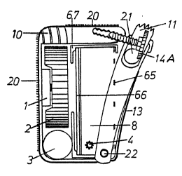
.'i~. 1 s~ws a fan and filter unit, which constitute the osntral main part o~
apparatu~.

Fig. 2 shows Ule cooling and humidifyin~ unit of the apparatus, which unit must be
regarded as optional ~quipment that is used only under certain weather and
temperature conditions.

Fig. 3 also shows additional equipment, i.e. an ionizer, which is only used under
parlicular air conditions.

- j WO 93/2416~ z~3 7iDlD6 PCI`/N093/0~088


Fig. 4 s~ows the lower balt, which i~ quite ess6~ntial to keep the main
apparstus (fi~. 1 ) in a stable and secure po~ition when the u~sr is in motion.

f~. 5 shows a so4alled swan's neck or mouth piece which rnay b~ us~d
advantag~ously in heavily pol3uted areas or when wind deflects the air s~r~Am
from the main appar~tus.

Fig. 6 shows an adju~tabie dir~ctin0 fin ~or the dir~:tion of air flow.

fig. 7 shows a cooling and humidifying unit, lighter ~han the unit of Fjg. 2, and more
suitable for use when mo~

Fig. 8 shows a smaller ionizer which i~ more suitable for ionkation of air entlsring the
filt~rs.

Fig. 9 shows the most commonly used position of the main apparatus on th~ body.

fig. 10 shows an embodiment of the apparatus with an ele~tronic auto c~ntrol unit on
top o~ the apparatus ~or ~utomatic focusing of sir flow towards the resp;ratory
organs of the user.

Fig. 11 shows an embodiment of the apparatus which provides the option of thick~r -
~ilters for use in mors polluted ar~as.

Fi~. 12 shows ~e use of ~e appa~atus in heavily pollut~d situations, where a mask is
neces&ary to k~p poisonous air away from the respiratory organs.

Fig. 13 sh~ws the use of the air purif~er in heavy air pollution where ther~ is a dan~er of
damage to eyesight.

F~8. 14 shows an embodiment of ~e apparatus havin~ a propeller type f;an.

fi~. 1 shows a unit consistin~ of a fan (2) and a filter unit ~8). The filter unit may comprise of an
active carbon filter, a pr~filter (~5) and a post-filter tB6). The fan sucks the air by the rear hatch
way t13) and throu~h the fillters (8,65,66). The air then passes throu~h the fan (2) and is th~reafter
hurled ~oward the user's respiratory or~ans. Filters may ~asily be changsd by opening the rear
hatch way (13) by way of a simple rapid coupling system, e.g. a maanet attachment or a screw
connection (14A). A full disconnection of the rear hatch way (13) is simply ~one by additionally

WO 93/24168 :~L3~ Pcr/Nog3/ooog~ ~


bonbin~ out~rard the tongue like pro~tionC t~tow tbe lower belt attachment ~ . Pulling O,n the
filter unit (8) and the filter c~ssette (67), makes the NiCd battery ~3) and the fan (2) easily
acces~ible. By loosening the fan oenter screw, the motor (1) i8 accessible for lubricati~n and
maintenance. The battery may altematively be reached by an exterior slide hatch as is the case in
one of ~he inventsr's prototypes. ~n another altemative, an exterior plu~ may be mounted for
ch~rging the ~attery, runnin~ the motor, cooling, elec~onics, etc. The wind di~ection fins ~10~ are
quite necess~ry to catch and forward the rotating air from the centrifu5~al fan. The 8peed re~ulator
(4) is quite necessary to obtain an air curr~nt of suitabl~ spe~d from the apparatus. The low~r belt
attachmenS ~22) has a ~nall plu~ enterin~ into the apparatus (fi~. 1) and another plu0 protmding for
attachment of the hoop or ring (68) on the lower belt tfig. 4). Between the rings (~8) there is an
elastic middle strap (~) which makes the hoops elasp fi~nly on to tho lower belt attachment ~22).
This solution also makes it possible ~o use ~ lower belt invisibly, if the user accepts that the
covering clothes enter between the belt anachment an~ the hoop ~88). By tumir~ an adjustment
screw ~ , it is easy to adjust the apparatus so that th~ user recei~es an ade~uate flow of air
dir~ct~y toward the nose and rnouth. The len~ths of the lower belt (fig. 4J and the neck strap (11)
are ~djustable by mean~ ~f a rear slide buckle, e.g. of th~ so~lled Fastex type. ,
Most people have an indent in the middle of the ohast due lo the shape of the rib ca~e. The middle
of the rear hatch ~13) on the apparatus may have a oonvex shape corresponding to the indent of
the ri~e~ The hwer i~lt (fi~}. 4) pulls the apparatus a~ainst U~ indent to stabilize it's posiUon
This solution o~fers more room for the filter unit (8) as well as cour~eracting pendulous mo~/ernents
of the apparatus when in motion.

The cooler and humidffier unlts (fi~. 2 ~nd fi~. 7) may bave a ~ratin~ andlor a pipe sys~em for
coolir~ and humidifying the air when it pa~ses the air duct (26) on the top of ~e apparatus.
Filters arran~ed in serics ~8) may comprise both of active carbon filters, electrostatic fllters, and
other filter types which contributa ~o the removal of harsnful ~ases and particles, ther~by improving
~he airfor respiration.

The electronic auto control unit (S0-68) consists inter slia of:
An electromotor ~ to direct the air flow sideways when the user is tuming his head to the
side. An.electromotor ~1) to direct the airflow bacl~rard and fonvard.
Detectors (S2,53), control electronics (SS), a beYel wheel control (S7~, side directional fin
156~, magnetic swift lock (t8).

Representative Drawing
A single figure which represents the drawing illustrating the invention.
Administrative Status

For a clearer understanding of the status of the application/patent presented on this page, the site Disclaimer , as well as the definitions for Patent , Administrative Status , Maintenance Fee  and Payment History  should be consulted.

Administrative Status

Title Date
Forecasted Issue Date Unavailable
(86) PCT Filing Date 1993-06-01
(87) PCT Publication Date 1993-12-09
(85) National Entry 1994-11-29
Examination Requested 1994-11-29
Correction of Dead Application 1999-10-27
Dead Application 2002-06-03

Abandonment History

Abandonment Date Reason Reinstatement Date
1997-06-02 FAILURE TO PAY APPLICATION MAINTENANCE FEE 1998-06-01
2001-06-01 FAILURE TO PAY APPLICATION MAINTENANCE FEE

Payment History

Fee Type Anniversary Year Due Date Amount Paid Paid Date
Application Fee $0.00 1994-11-29
Maintenance Fee - Application - New Act 2 1995-06-01 $50.00 1995-05-18
Maintenance Fee - Application - New Act 3 1996-06-03 $50.00 1996-05-16
Reinstatement: Failure to Pay Application Maintenance Fees $200.00 1998-06-01
Maintenance Fee - Application - New Act 4 1997-06-02 $50.00 1998-06-01
Maintenance Fee - Application - New Act 5 1998-06-01 $75.00 1998-06-01
Maintenance Fee - Application - New Act 6 1999-06-01 $75.00 1998-06-01
Maintenance Fee - Application - New Act 7 2000-06-01 $75.00 1998-06-01
Owners on Record

Note: Records showing the ownership history in alphabetical order.

Current Owners on Record
HANSEN, IVER
Past Owners on Record
None
Past Owners that do not appear in the "Owners on Record" listing will appear in other documentation within the application.
Documents

To view selected files, please enter reCAPTCHA code :


To view images, click a link in the Document Description column. To download the documents, select one or more checkboxes in the first column and then click the "Download Selected in PDF format (Zip Archive)" or the "Download Selected as Single PDF" button.

List of published and non-published patent-specific documents on the CPD .

If you have any difficulty accessing content, you can call the Client Service Centre at 1-866-997-1936 or send them an e-mail at CIPO Client Service Centre.


Document
Description 
Date
(yyyy-mm-dd) 
Number of pages   Size of Image (KB) 
Cover Page 1995-11-18 1 26
Description 1995-11-18 4 254
Abstract 1995-11-18 1 58
Claims 1995-11-18 2 112
Drawings 1995-11-18 2 98
Claims 2001-11-22 1 76
Claims 2001-01-03 4 130
Claims 1997-06-18 4 122
Fees 1997-08-25 6 345
Correspondence 1996-07-09 27 1,033
Prosecution-Amendment 2001-05-22 3 108
Prosecution-Amendment 2001-11-22 3 97
Fees 1998-06-11 5 277
Correspondence 1998-07-02 1 1
Correspondence 1998-07-02 1 2
Correspondence 1998-07-15 1 24
Correspondence 1999-12-03 1 2
Correspondence 2000-12-20 1 16
Assignment 1994-11-29 5 200
PCT 1994-11-29 12 461
Prosecution-Amendment 1994-11-29 11 497
Fees 1996-05-16 1 33
Fees 1995-05-18 1 38