Note: Descriptions are shown in the official language in which they were submitted.
2137047
NORMALLY WHITE TWISTED NEMATIC LCD WITH
RETARDATION FILMS ON OPPOSITE SIDES OF
LIQUID CRYSTAL MATERIAL FOR IMPROVED VIEWING ZONE
This invention relates to a liquid crystal display
having at least two retardation films, one on each side
of a liquid crystal layer. More particularly, this
invention relates to a normally white liquid crystal
display which includes at least one retardation film
having a retardation value of 80 - 200 nm on each side of
the liquid crystal layer.
BACKGROUND OF THE INVENTION
Liquid crystal materials are useful for electronic
displays because light traveling through a layer of
liquid crystal (LC) material is affected by the
anisotropic or birefringent value (4N) of the material,
which in turn can be controlled by the application of a
voltage across the liquid crystal material. Liquid
crystal displays are desirable because the transmission
or reflection of light from an external source, including
ambient light and backlighting schemes, can be controlled
with much less power than was required for the
illuminance materials used in other previous displays.
Liquid crystal displays (LCDs) are now commonly used in
such applications as digital watches, calculators,
portable computers, avionic cockpit displays, and many
other types of electronic devices which utilize the
1
2137047
liquid crystal display advantages of long-life and
operation with low voltage and power consumption.
The information in many liquid crystal displays=is
presented in the form of a matrix array of rows and
columns of numerals or characters, which are generated by
a number of segmented electrodes arranged in such a
matrix pattern. The segments are connected by individual
leads to driving electronics, which apply a voltage to
the appropriate combination of segments to thereby
display the desired data and information by controlling
the light transmitted through the liquid crystal
material. Graphic information in, for example, avionic
cockpit applications or television displays may be
achieved by a matrix of pixels which are connected by an
X-Y sequential addressing scheme between two sets of
perpendicular conductor lines (i.e. row and column
lines). More advanced addressing schemes use arrays of
thin film transistors, diodes, MIMS, etc. which act as
switches to control the drive voltage at the individual
pixels. These schemes are applied predominantly to
twisted nematic liquid crystal displays, but are also
finding use in high performance versions of super twisted
liquid crystal displays.
Contrast is one of the most important attributes
determining the quality of both normally white (NZa) and
normally (NB) liquid crystal displays. Contrast, or the
contrast ratio, is the difference between OFF state
2
2137047
transmission versus ON state transmission. In normally
black liquid crystal displays, the primary factor
limiting the contrast achievable in these LCDs is the
amount of light which leaks through the display in the
darkened or OFF state. In normally white (NW) LCDs, the
primary factor limiting the contrast is the amount of
light which leaks through the display in the darkened or
ON state. These problems are compounded in a bright
environment, such as sunlight, where there is a
considerable amount of reflected and scattered ambient
light. In color liquid crystal displays, light leakage
causes severe color shifts for both saturated and gray
scale colors. These limitations are particularly
important for avionic applications, where the copilot's
viewing of the pilot's displays is important.
In addition, the legibility of the image generated
by both normally black (NB) and normally white (NW)
liquid crystal display devices depends on the viewing
angle, especially in the matrix address device with a
large number of scanning electrodes. Absent a
retardation film, the contrast ratio of a typical NB or
NW liquid crystal display is usually at a maximum only
within a narrow viewing (or observing) angle centered
about normal incidence (0 horizontal viewing angle and
0 vertical viewing angle) and drops off as the angle of
view is increased.
3
2137047
It would be a significant improvement in the art to
pro-,ide a liquid crystal display capable of presenting a
high quality, high contrast image over a wide field of
view.
Normally black liquid crystal displays are quite
sensitive to cell gap, or the thickness "d" of the liquid
crystal material, as well as to the temperature of the
liquid crystal material. Therefore, normally black
liquid crystal displays must be manufactured in
accordance with rather specific tolerance parameters
related to the cell gap of the display making them both
difficult and expensive to make. One way in which to
compensate for the normally black displays high
sensitivity to cell gap is to provide such a multi-
colored display with a multi-gap design wherein the
thickness "d" of the liquid crystal material for each
colored subpixel is matched to the first transmission
minimum of the color of that subpixel. See, for example,
U.S. Patent No. 4,632,514 which utilizes the multi-gap
approach by varying the liquid crystal material thickness
"d" for the red, green, and blue subpixels therein so as
to match the thickness "d" of each subpixel to the three
different transmission minimums representative of the
colors red, green, and blue. This increases, of course,
the difficulty and expense of manufacturing this type of
LCD.
4
2137047
Although a normally black display is rather
sensitive to temperature and cell gap "d", a significant
advantage associated with this type of liqu-'A-d crystal
display is that it provides good contrast ratios at wide
viewing ahgles. Thus, a viewer may satisfactorily
observe the data of the display throughout a wide range
of viewing angles. Contrast ratio curves of, for
example, 10:1 in normally black displays often extend up
to viewing angles of, for example, 0 vertical, 60
horizontal. The fact that normally black displays have
such good contrast ratios at such large horizontal
viewing angles enables them to be used in commercial
applications where such viewing angles are required or
preferred. Furthermore, NB displays generall experience
more darkened state leakage than do NW displays.
Turning now to normally white liquid crystal
displays, NW displays are fairly insensitive to the
temperature and cell gap "d" of liquid crystal material.
This allows for the manufacturing tolerances associated
with the development of normally white displays to be
lessened. Hence, normally white displays are easier and
cheaper to manufacture then their normally black
counterparts. However, while normally white LCDs are
less sensitive to temperature and cell gap than normally
black LCDs, their contrast ratios at large viewing angles
are generally small relative to those of normally black
displays. For example, 10:1 contrast ratio curves in
5
2137047
normally white displays often only extend up to
horizontal viewing angles of about 0 vertical, 35
horizontal. This is significantly less than the extent
to which the same contrast ratio curves extend
horizontally in normally black displays. Therefore,
while normally white LCDs are easier and cheaper to
manufacturer than normally black liquid crystal displays,
they have a smaller range of satisfactory viewing angles
than do normally black displays. It would satisfy a long
felt need in the art if one could provide a NW display
which had good contrast ratios at large viewing angles.
Several types of liquid crystal pixels or cells are
in widespread use in flat panel displays. Active matrix
addressing allows such displays to present a full color
image with high resolution. When viewed directly at a
normal or ON axis viewing angle (0 vertical, 0
horizontal viewing angle), a liquid crystal display of
either the normally black or normally white type provides
a generally high quality output, especially when the cell
gap "d" is matched to the first transmission minimum, but
the image degrades and contrast ratios decrease at
increased viewing angles. This occurs because liquid
crystal cells operate by virtue of the anisotropic or
birefringent effect exhibited by their liquid crystal
layerwhich includes a large number of anisotropic liquid
crystal molecules. Such a material will be positively
uniaxially birefringent (i.e., the extraordinary
6
2137047
refractive index is larger than the ordinary refractive
index). The phase retardation effect such a liquid
crystal material has on light passing through it
inherently varies or increases with the inclination angle
of light, leading to lower contrast ratios and a lower
quality image at larger viewing angles. By introducing
an optical compensating element (or retarder) into the
liquid crystal pixel or cell, however, it is possible to
correct for the unwanted angular effects and thereby
maintain higher contrast at both normal and larger
viewing angles than otherwise possible.
The type and orientation of optical compensation or
retardation required depends in part upon the type of
display, normally black or normally white, which is used.
In a normally black (NB) twisted nematic display,
the twisted nematic liquid crystal material is placed
between polarizers whose transmission axes are parallel
to one another. In the unenergized OFF state (no voltage
above the threshold voltage Vth is applied across the
liquid crystal material), normally incident light from
the backlight is first polarized by the rear polarizer
and in passing through the pixel or cell has its
polarization direction rotated by the twist angle of the
liquid crystal material dictated by the buffing zones.
This effect is known as the twisting effect. The twist
angle is set, for example, to be about 90' so that the
light is blocked or absorbed by the front or output
7
2137047
polarizer when the pixel is in the OFF state. When a
voltage is applied via electrodes across the normally
black pixel, the liquid crystal molecules are forced to
more nearly align with the electric field, eliminating
the twisted nematic optical effect of the LC material.
In this orientation, the optical molecular axes of the
liquid crystal layer molecules are perpendicular to the
cell walls. The liquid crystal layer then appears
isotropic to normally incident light, eliminating the
twist effect such that the light polarization state is
unchanged by propagation through the liquid crystal layer
so that light can pass through the output polarizer.
Patterns can be written in a normally black display by
selectively applying a variable voltage to the portions
of the display which are to appear illuminated.
Turning again to normally white (NW) LCD cells, in a
normally white liquid crystal display configuration, a
twisted nematic cell preferably having a twist angle of
about 80 - 100 (most preferably about 90 ) is placed
between polarizers which have substantially crossed or
perpendicular transmission axes, such that the
transmission axis of each polarizer is either parallel
(P-buffed) or perpendicular (X-buffed) to the buffing
direction or orientation of the liquid crystal molecules
in the interface region of the liquid crystal material
adjacent each polarizer. In other words, normally white
cells can be either P-buffed where both polarizer axes
8
2137047
are substantially parallel to their respective adjacent
buffing zones, or X-buffed where both polarizer axes are
substantially perpendicular to their respective adjacent
buffing zones.
This NW orientation of the polarizers reverses the
sense of light and dark from that of the normally black
displays discussed above. The OFF or unenergized (no
applied voltage above Vth across the liquid crystal
material) areas appear light in a normally white display,
while those which are energized appear dark.
The problem of ostensibly dark areas appearing light
or colored when viewed at large angles still occurs,
however, thereby creating the aforesaid lowered contrast
ratios at reasonably large viewing angles. The reason
for the reduced contrast ratios at large viewing angles
in normally white displays is different than the reason
for the problem in normally black displays. In the
normally white energized darkened areas, the liquid
crystal molecules tend to align with the applied electric
field. If this alignment were perfect, all of the liquid
crystal molecules in the cell would have their long axes
normal to the glass substrate or cell wall. In the
energized state, the normal white display appears
isotropic to normally incident light, which is blocked by
the crossed polarizers, thus, resulting in a darkened
pixel or subpixel.
9
CA 02137047 2003-04-22
The loss of contrast with increased viewing angles
in normally white pixels or displays occurs primarily
because the horneotropic 1::..quid crystal layer does not
appear isotropic to OFF axis or OFF normal light. Light
directed at OFF normal an(Iles through the liquid crystal
material propagates in two modes due to the anisotropy or
birefringence (AN) of tr.e li_qui.d crystal :Layer, with a
phase delay between these rnodes which increases with the
incident angle of light. 'Phis phase dependence on the
incident angle introduces an ellipticity to the
polarization state whicr..is then incompletely
extinguished x_)y the front or exit polarizer in the
normally white cell, giv.'~ng rise to light leakage.
Because of the normally white symmetry the birefringence
has no azimuthe:l dependence.
Accordingly, what s needed in normally whi-e
displays is an opt.:i.cal c:o:mpensatinq or retarding element
which introduces a phasf: delay that restores the original
polarization state of the light, allowing the light to be
blocked by the output pc;larizer in t he ON state. Optical
compensating elements o.- retarders for normally white
displays are kriown in tlie art and are disclosed, for
example, in U.S. Patent Nos. 5,184,236; 5,196,953;
5,138,474; and 5,071,99". It is known that the polyimides
2E. and copolyimides disclo:sed by aforesaid U.S. Patent No.
5,071,997 can be used a;:;
1 0
2137047
negative birefringent retarding elements in normally
white liquid crystal displays and are said to be custom
tailorable to the desired negative birefringent values
without the use of stretching. The polyimide retardation
films of 5,071,997 are uniaxial but with an optical axis
oriented in the Z direction which is perpendicular to the
plane defined by the film.
Quite often, the retardation films or plates used in
conjunction with normally white displays have a negative
birefringent value. However, in certain cases,
retardation films having a positive birefringent value
are used in combination with such normally white cells.
An example of this is U.S. Patent No. 5,184,236 which
will be discussed more fully below.
Figure 1 is a contrast ratio curve graph for a prior
art normally white light valve pixel. The light valve
for which the contrast ratio curves are illustrated in
Figure 1 includes a rear polarizer having a transmission
axis defining a first direction, a front or exit
polarizer having a transmission axis defining a second
direction wherein the first and second directions are
substantially perpendicular to one another, a liquid
crystal material having a cell gap "d" of 5.86 m, a rear
buffing zone oriented in the second direction, and a
front buffing zone orientated in the first direction.
The temperature was 34.4 C when the graph illustrated by
Figure 1 was plotted. This light valve pixel did not
11
2137047
include a retarder. The above-listed parameters with
respect tO Figure 1 are also applicable to Figures 2 and
3.
The contrast ratio graph of Figure 1 was plotted
utilizing a 6.8 V driving voltage VoN, and a 0.2 volt
VOFF= As can be seen in Figure 1, the 10:1 contrast ratio
curve extends along the 0 vertical viewing axis only to
angles of about -40 horizontal and +38 horizontal.
Likewise, the 30:1 contrast ratio curve extends along the
0 vertical viewing axis only to horizontal angles of
about 30 . This graph is illustrative of the problems
associated with normally white liquid crystal displays in
that their contrast ratios at large horizontal and
vertical viewing angles are fairly low.
Figure 2 is a contrast ratio curve graph for the
normally white light valve described above with respect
to Figure 1. However, the Figure 2 graph was plotted
utilizing a VoN of 5.0 volts and a VOFF of 0.2 volts.
Again, the temperature was 34.4 C. As can be seen by
comparing the graphs of Figure 1 and Figure 2, as the
voltage applied to the liquid crystal material decreases,
as in Figure 2, the contrast ratio curves expand
horizontally and contract vertically. The 10:1 contrast
ratio curve of Figure 2 along the 0 vertical viewing
axis extends a total of about 85 as opposed to only 78
in Figure 1. Also, the 30:1 contrast ratio curve of
Figure 2 along the 0 vertical viewing axis extends
12
2137047
horizontally about 67 as opposed to only about 58 in
Figure 1. With respect to vertical viewing angles, the
contrast ratio curves of 10:1 and 30:1 in Figure 2 do not
extend along the 0 horizontal viewing axis to the
negative vertical extent that they did in Figure 1.
Accordingly, while the normally white light valve of
Figures 1 - 3 has less than desirable contrast ratios at
large viewing angles, the contrast ratios expand
horizontally and contract vertically as the voltage
across the liquid crystal material decreases.
Figure 3 is a driving voltage versus intensity plot
for the light valve pixel described above with respect to
Figures 1 - 2 illustrating the gray level characteristics
of the pixel. The various curves represent horizontal
viewing angles from -60 to +60 along the 0 vertical
viewing axis.
Gray level performance of a liquid crystal display
is very important. Conventional liquid crystal displays
utilize anywhere from about eight to sixty-four different
driving voltages. The different driving voltages are
referred to as "gray level" voltages. The intensity of
the light transmitted through the pixel or display
depends upon the driving voltage. Accordingly, gray
level voltages are used to generate different shades of
different colors and to create different colors when
these shades are mixed with one another. Preferably, the
higher the driving voltage in a NW display, the lower the
13
2137047
intensity of light transmitted therethrough. Likewise
then, the lower the drivinq voltage, the higher the
intensity of light emitted from the preferred forms of a
normally white display. The opposite is true in a
normally black display. Thus, by utilizing multiple gray
level driving voltages, one can manipulate either an NW
or NB liquid crystal display pixel to emit a desired
intensity of light. A gray level VoN is any voltage
greater than Vth up to about 5.0 - 6.5 V.
Gray level intensity performance for LCDs is
dependent upon the displays' driving voltage. It is
desirable in gray level performance of NW displays to
have an intensity versus driving voltage curve wherein
the intensity of the light emitted from the pixel
continually and monotonically decreases as the driving
voltage increases. In other words, it is desirable to
have gray level performance in a pixel such that the
intensity at 6.0 volts is less than that at 5.0 volts,
which is in turn less than that at 4.0 volts, which is
less than that at 3.0 volts, which is in turn less than
that at 2.0 volts, etc. Such good gray level curves
across wide ranges of viewing angles allow the intensity
of radiation emitted from the pixel to be easily
controlled.
Turning again now to Figure 3, the intensity versus
driving voltage curves illustrated therein with respect
to the prior art light valve pixel of Figures 1 - 2
14
2137047
having no retardation film are undesirable because of the
inversion hump present in the area of the curves having
voltages greater than about 3.2 volts. The term
"inversion hump" means that the intensity aspect of the
curve monotonically decreases as the driving voltage
increases in the range of about 1.6 - 3.0 volts, but at a
driving voltage of about 3.2 volts, the intensities at a
plurality of viewing angles begin to rise as the voltage
increases from about 3.2 volts to 6.8 volts. This rise
in intensity as the voltage increases is known as an
"inversion hump." The inversion hump of Figure 3
includes only a rise portion. However, such inversion
humps often include both a rise and fall portion. The
presence of this inversion hump with respect to a
plurality of horizontal viewing angles as shown in Figure
3 means that as gray level voltages between, for example,
1.6 and 3.0 volts increase, the intensity of radiation
emitted from the pixel decreases accordingly. However,
as gray level voltages above 3.0 volts increase from 3.2
volts all the way up to 6.8 volts, the intensity of
radiation emitted from the pixel increases. This is
undesirable. A perfect driving voltage versus intensity
curve would have a decreased intensity for each increase
in gray level driving voltage. In contrast to this, the
inversion hump represents an increase in intensity of
radiation emitted from the light valve pixel for each
increase in gray level driving voltage above about 3.2
2137047
volts for certain viewing angles. Accordingly, it would
satisfy a long felt need in the art if a liquid crystal
display and pixels therein could be provided with no or
little inversion. In other words, the smaller the rise
in intensity for an increase in driving voltage at all
gray levels, the better.
Figure 4 is a schematic illustration showing an
optical arrangement of a normally white liquid crystal
display device disclosed in U.S. Patent No. 5,184,236.
As illustrated, the LCD includes a rear polarizer 111, a
rear retardation plate or film 113, a liquid crystal cell
119 including a liquid crystal material sandwiched
between a rear orientation or buffing zone oriented in
direction Ao and a front orientation or buffing zone
oriented in direction A,, a front retardation film 114,
and finally a front polarizer 112.
The rear polarizer 111 is provided at the light
incident side of the liquid crystal layer 119, a front or
exit polarizer 112 is provided at the light exit side of
the liquid crystal layer 119, a rear retardation film 113
is provided between the liquid crystal layer and the
polarizer 111, and a front retardation film 114 is
provided between the liquid crystal layer and the front
polarizer 112. This prior art NW display is "P-buffed"
because the rear polarizer transmission axis Pi is
parallel to the rear orientation direction Ao, and the
16
2137047
front polarizer transmission axis P2 is parallel to the
front orientation direction Ai.
The product of parameters "AN = d" of the liquid
crystal layer 119 is set in the range of 450 - 550 nm.
The liquid crystal material of U.S. Patent No. 5,184,236
is left handed as defined in the art. The aligning
direction of the rear orientation film on the light
incident side of the liquid crystal layer 109 is a
rubbing direction A. inclined at approximately 45 with
respect to the side of the liquid crystal cell. The
aligning direction of the orientation or buffing film on
the front side of the liquid crystal layer is oriented in
direction Ai which is rotated about 90 in a
counterclockwise direction from the orientation direction
Ao of the orientation film on the rear side of the liquid
crystal material. Therefore, the liquid crystal layer
119 sandwiched between the opposing orientation films is
twisted substantially 90 . The pretilting angle of the
liquid crystal molecules is approximately 1 .
The rear linear polarizer 111 has a transmission
axis Pi which is parallel to the orientation direction Ao,
while the front polarizer 112 has a transmission axis
direction P2 which is parallel to the front orientation
direction Al. The transmission axes of the front and rear
polarizers 112 and 111 are perpendicular to one another
thereby defining a normally white liquid crystal display.
The rear retardation plate or film 113 is so arranged
17
2137047
that its optical axis R, is either parallel to or crosses
at 90 to the rear rubbinq direction Ao. The front
retardation film 114 is so arranged that its optical axis
R2 is either parallel to or crosses at 90 to the rubbing
direction A,. These retardation films 113 and 114 are
formed to have equal retardation values (d = AN) where
"d" is the thickness of the retardation film and "AN" is
the anisotropic or birefringent value of the retardation
film. The retardation values of the retardation films
113 and 114 are set in the range of 300 - 400 nm. The
front and rear retardation films are formed of the same
material such as, for example, a polycarbonate or
polyvinyl alcohol, and the outer surfaces thereof are
preferably covered with a protective film made of
triacetyl cellulose or the like.
The orientation or buffing directions of prior art
Figure 4 are "six o'clock buffed." The term "six o'clock
buffed" means that the rear and front'orientation
directions Ao and Al are oriented in directions so as to
provide a viewing zone having an extended region in the
six o'clock area of the graphs shown in Figures 5A - 5D.
In other words, because the orientation direction Ao goes
from the upper left to the lower right as shown in Figure
4, and orientation direction A, goes from lower left to
upper right, the resulting viewing zone has better
contrast as shown in Figures 5A - 5D in the negative
18
2137047
vertical region below the 0 vertical viewing axis. This
is what is meant by the phrase "six o'clock buffed."
Alternatively, if the orientation direction Ao went
from the lower right to the upper left, and the
orientation direction Al was directed from the upper right
to the lower left, then the display of Figure 4 would
have been "twelve o'clock buffed" and would have provided
a viewing zone having better contrast ratios in the
positive vertical viewing angles instead of the negative
vertical viewing angles. The six o'clock buffed LCDs of
Figures 4 and 5A - 5D illustrate viewing zones with
better contrast ratios in the negative vertical area
below the 0 vertical viewing axis as opposed to the
positive vertical viewing area above the 0 vertical
viewing axis.
In the prior art liquid crystal display of Figure 4,
the contrast ratios are measured in Figures 5A - 5D for
the four possible cases of retardation film orientation,
when the value of d- AN of a liquid crystal layer 119 is
set to 510 nm and the retardation value of both
retardation films 113 and 114 is set to 350 nm (the value
measured by the light having a wavelength of 589 nm).
The four cases are as follows.
Figure 5A shows contrast ratio curves for the case
where the optical axes of the rear and front retardation
films 113 and 114 are disposed together in parallel to
the rear rubbing direction A.. The solid or outer
19
2137047
contrast ratio curve in Figures 5A - 5D represents a
contrast ratio of 10:1. The inner or equally broken
contrast curve in Figures 5A - 5D represents a contrast
ratio of 100:1. The intermediate contrast ratio curve in
Figures 5A - 5D represents a contrast ratio of 50:1.
Furthermore, in the graphs of Figures 5A - 5D, each
circle represents a 10 shift in viewing angle. In other
words, the center of the graph represents a 0 vertical
and 0 horizontal viewing angle, the first circle
represents 10', the second circle 20 , etc. As can be
seen in Figure 5A, the 10:1 contrast ratio curve extends
horizontally along the vertical 0' viewing axis to
about -37" and +40", and extends upwardly along the 0
horizontal viewing axis to about 15' vertical.
Figure 5B shows contrast ratio curves for the case
where the optical axis Ri of the rear retardation film 113
is disposed in parallel to the orientation direction Ao,
and the optical axis R2 of the front retardation film 114
is disposed perpendicular_to the rubbing direction A0.
The direction Ri is parallel to the rear polarizer axis
Pj , and R2 is parallel to the front polarizer axis Pz. As
can be seen in Figure 5B, the 10:1 contrast ratio curve
extends along the 0' horizontal viewing axis only to
about 15 vertical. Also, the 50:1 contrast ratio curve
extends along the 0' horizontal viewing axis only to
about 5 vertical.
2137047
Figure 5C shows contrast ratio curves for the case
where the optical axes of the rear and front retardation
films 113 and 114 are arranged in parallel with one
another and cross at 90 to the rear buffing direction
Ao. In Figure 5C, the 10:1 contrast ratio curve extends
upward along the 0 horizontal viewing axis only to about
vertical. Also, the 10:1 contrast ratio curve
extends along the 0 vertical viewing axis a total of
about 75 - 80 .
10 Figure 5D shows contrast ratio curves for the case
where the optical axis Ri of the rear retardation film 113
is arranged to cross at 90' to the rubbing direction Ao,
and the optical axis R 2 of the front retardation film 114
is arranged in parallel to rear orientation direction A0.
15 In Figure 5D, the 10:1 contrast ratio curve extends
horizontally along the 0 vertical viewing axis a total
of about 60 - 65 . Also, the 10:1 contrast ratio curve
in Figure 5D extends upward along the 0 horizontal
viewing axis only to about +15 vertical.
It was known prior to our invention to rotate
retardation films to adjust the viewing zones of LCDs.
For example, U.S. Patent No. 5,184,236 teaches rotating
the optical axes of retardation films 15 or less when
two such films are disposed on a single.side of the
liquid crystal material. The axes of the retardation
films are rotated either in the clockwise or
counterclockwise direction for the purpose of adjusting
21
2137047
the viewing zone. However, when the retardation films of
this patent are rotated, the symmetry of the viewing zone
is substantially distorted thereby creating viewing zones
which are not substantially symmetrical about the 0
horizontal viewing axis. Furthermore, this patent does
not teach rotating one or both optical axes of rear and
front retardation films 15 or less for the purpose of
adjusting the location of the display's viewing zone when
the display includes rear and front retardation films
with a liquid crystal layer therebetween.
Figure 6 illustrates the angular relationships
between the horizontal and vertical viewing axes and
angles described herein relative to a liquid crystal
display and conventional LCD angles 0 and e. The +X, +Y,
and +Z axes shown in Figure 6 are also defined in other
figures herein. Furthermore, the "horizontal viewing
angles" (or XANG) and "vertical viewing angles" (or YANG)
illustrated and described herein may be transformed to
conventional LCD angles and 6 by the following
equations:
TAN (XANG) - COS (~) = TAN (O)
SIN (YANG) = SIN (O) = SIN (~)
or
COS ( ) = COS (YANG) COS (XANG)
TAN (0) = TAN (YANG) - SIN (XANG)
Figures 7 - 10 are colnputer simulation contrast
ratio curve graphs of a normally white liquid crystal
22
2137047
display having a cell gap "d" of 5.70 m. The display
includes a rear polarizer having a transmission axes
defining a first direction, a rear.retardation film
having an optical axis parallel to the first direction, a
rear buffing zone oriented perpendicular to the first
direction, a front buffing zone parallel to the first
direction, a front retardation film having an optical
axis perpendicular to the first direction, and a front or
exit polarizer having a transmission axis perpendicular
to the first direction. The retardation films are of the
positively birefringent uniaxial type. This LCD of
Figures 7 - 10 is not prior art to this invention but is
included in this section for the purpose of later
comparison with certain embodiments of this invention.
Figure 7 is a computer simulation contrast ratio
graph of the aforesaid normally white liquid crystal
display wherein the wavelength of light utilized was red
at 630 nm, VON was 6.8 volts, and VoFF was 0.9 volts. The
retardation value of both the front and rear retardation
films of the display simulated in Figures 7 - 10 was 320
nm. As can be seen in Figure 7, the 10:1 contrast ratio
curve extends along the 0 vertical viewing angle from
horizontal angles of about -40 to +40 thereby defining
along the 0 vertical viewing axis a 10:1 total viewing
zone of about 80 .
Figure 8 is a computer simulation graph of the
aforesaid display also simulated by Figure 7. The
23
2137047
difference between the graph of Figure 8 and the graph of
Figure 7 is that a 5.0 VON was used as a parameter in
Figure 8. As can be seen, a reduction in VoN results in a
shifting upward of the viewing zone to a position
5. centered substantially above the 0 vertical viewing
axis. Also, a reduction in VoN results in a vertical
shrinking of the viewing zone.
Figure 9 is a computer simulation graph illustrating
the contrast ratios of the aforesaid display wherein the
retardation value of the front and rear retardation films
is 320 nm, and the parameter V ON is 6.8 volts. The
difference between the graph of Figure 7 and the graph of
Figure 9 is that a green wavelength of 550 nm was used in
Figure 9. The reason for the higher contrast for the
green wavelength as opposed to the red wavelength of
Figure 7 is that the cell gap of 5.70 m is more nearly
matched to the first transmission minimum for the green
wavelength than that of the red wavelength. Accordingly,
the green wavelength experiences higher contrast ratios
in the center of its viewing zone. Again, the 10:1
contrast ratio curve in Figure 9 extends horizontally
along the 0 vertical viewing axis a total of about 75 .
Figure 10 is a computer simulation graph of the
aforesaid display wherein a blue wavelength of 480 nm was
used. As in the graphs of Figures 7 - 9, the retardation
value for the rear and front retardation films or plates
was 320 nm. The 10:1 blue contrast ratio curve shown in
24
2137047
Figure 10 extends horizontally along the 0 vertical
viewing axis a total of about 75 . The blue contrast
ratio viewing zone is shifted slightly upward from that
shown in Figure 7 with respect to the red wavelength.
As can be seen from the contrast ratio curves of
Figures 1, 2, and 7 - 10, it would be highly desirable if
one could provide a normally white liquid crystal display
with a viewing zone including contrast ratio curves which
extended to large horizontal and vertical viewing angles.
U.S. Patent No. 4,984,874 discloses a liquid crystal
display device having front and rear retardation films
having retardation values of about 300 nm. A liquid
crystal layer including front and rear buffing zones is
sandwiched between the retardation films. The rear
retardation film functions so as to convert linearly
polarized light into elliptically polarized light while
the front retardation film converts elliptically
polarized light exiting the liquid crystal material into
linear polarized light before it reaches the front or
exit polarizer. The twist angle of the liquid crystal
material of U.S. Patent No. 4,984,874 is about 180 -
270'.
U.S. Patent No. 5,107,356 discloses a normally black
liquid crystal display including first and second
polarizers having parallel transmission axes. A liquid
crystal material of this patent is sandwiched between
front and rear retardation films.
2137047
While it is known to dispose rear and front 300 -
600 nm retardation films or plates on opposite sides of a
liquid crystal layer of a P-buffed display, the prior art
does not disclose providing a normally white X-buffed
liquid crystal display or pixel with rear and front
retardation films having 80 - 200 nm retardation values
in order to achieve a high contrast ratio over a
predetermined range of viewing angles. The prior art
also does not disclose symmetrically rotating the optical
axes of such rear and front retardation films so as to
shift the centered position of the display's viewing zone
to a point below the 0 vertical viewing axis, and thus,
away from inversion areas present above the 0 vertical
viewing axis.
The terms "clockwise" and "counterclockwise" as used
herein mean as viewed from the viewer's or observer's
side of the liquid crystal display or pixel.
The term "rear" when used herein but only as it is
used to describe substrates, polarizers, electrodes,
buffing zones, retardation films, and orientation films
means that the described element is on the incident light
side of the liquid crystal material, or in other words,
on the side of the liquid crystal material opposite the
viewer.
Each of the displays and light valves described
herein is/was "X-buffed" unless otherwise shown or
described.
26
2137047
The term "front" when used herein but only as it is
used to describe substrates, polarizers, electrodes,
buffing zones, retardation films, and orientation films
means that the described element is located on the viewer
side of the liquid crystal material.
The LCDs and light valves of Figures 1 - 3 and 7 -
45 herein include left handed liquid crystal material
with a birefringence (AN) of 0.084 at room temperature.
The term "retardation value" as used herein means
l0 "d = AN" of the retardation film or plate, wherein "d" is
the film thickness and "AN" is the film birefringence
(either positive or negative).
The term "interior" when used herein to describe a
surface or side of an element, means the side or surface
closest to the liquid crystal material.
The term "light valve" as used herein means a liquid
crystal display pixel including a rear polarizer, a rear
retardation film (unless otherwise specified), a rear
transparent substrate, a rear continuous electrode, a
rear orientation film, a LC layer, a front orientation
film, a front continuous pixel electrode, a front
substrate, a front retardation film (unless otherwise
specified), and a front polarizer in that order, without
the presence of color filters and driving active matrix
circuitry such as TFTs.
The term "contrast ratio" as used herein means the
transmission of light through the display or pixel in the
27
- 2137047
OFF or white state versus the amount of transmission
through the display or pixel in the ON or darkened state.
It is apparent from the above that there exists a
need in the art for a normally white liquid crystal
display wherein the viewing zone of the display includes
high contrast ratios at extended or large vertical and
horizontal viewing angles. There also exists a need in
the art to center the viewing zone of a NW LCD at a
position distant from inversion areas present at or above
the 0 vertical viewing axis.
SUMMARY OF THE INVENTION
Generally speaking this invention fulfills the
above-described needs in the art by providing a liquid
crystal display comprising:
a plurality of pixels, each of these pixels being
comprised of a pair of driving electrodes and a twisted
nematic liquid crystal material located therebetween, the
liquid crystal material being of a thickness "d" and
having an anisotropy AN such that the product of d- AN
is about 400 - 550 nm and wherein the liquid crystal
material is capable of twisting at least one normally
incident visible wavelength of light passing therethrough
in an amount of about 80 - 100 ;
a rear, light-entrance polarizer having a
transmission axis oriented in a first direction;
28
2137047
a front, light-exit polarizer having a transmission
axis oriented in a second direction with respect to the
first direction thereby to define a normally white
display;
a rear retardation film disposed between the rear
polarizer and the twisted nematic liquid crystal
material;
a front retardation film disposed between the front
polarizer and the liquid crystal material; and
wherein the transmission axes of the polarizers and
optical axes of the retardation films are so arranged
each with respect to the others so as to achieve a white
light contrast ratio of at least about 10:1 over a
horizontal angular span of at least about 100 and over a
vertical angular span of greater than about 55 .
In the preferred forms of this invention contrast
ratios of at least about 10:1 over a horizontal angular
span of at least about 120 and over a vertical angular
span greater than about 60 are achieved; particlarly
when about 6.0 volts is applied to the display.
In still further preferred forms of this invention
the above-described 10:1 contrast ratios are achieved
while at the same time 30:1 contrast ratios of at least
about 80 over the horizontal angular span and about 30
over the vertical angular span are also achieved. In a
particularly preferred form of this invention,
29
2137047
furthermore, not only are the above-described ratios
achieved but a contrast ratio of about 50:1 is also
achieved over a horizontal angular span of about 85 and
over a vertical angular span of about 30 . In such
embodiments, furthermore, it is preferred to design the
display so that the product of d oN is approximately
a
matched to the first minimum of a single, pre-selected
color whose wavelength is X. Such a color is usually
red, green, or blue, but may be any other color desired.
In addition, this invention further fulfills the
above-described needs in the art by providing a normally
white liquid crystal display including a plurality of
pixels comprising: a twisted nematic liquid crystal
layer which twists at least one normally incident visible
wavelength of light about 80 - 100 as it passes
therethrough; a first retardation film on a first side of
said liquid crystal layer; a second retardation film on a
second side of said liquid crystal layer whereby said
liquid crystal is disposed between said first and second
retardation films; and wherein said first and second
retardation films each are uniaxial and have positive or
negative retardation values of from about 80 - 200 nm,
and wherein the optical axes of the retardation films are
so arranged each with respect to the other so as to
achieve a high contrast ratio over a predetermined range
of viewing angles.
2137047
In certain preferred embodiments of this invention,
the first and second retardation films each have an
optical axis, and wherein the optical axis of the first
retardation film defines a first direction and the
optical axis of the second retardation film defines a
second direction, and wherein the first and second
directions are different by about 75 - 100 .
In certain other preferred embodiments of this
invention the display further includes a first polarizer
substantially adjacent the first retardation film and a
second polarizer substantially adjacent the second
retardation film, whereby the first and second
retardation films are disposed between the first and
second polarizers.
In certain further preferred embodiments of this
invention the display when about 6.0 volts is applied
thereto has a white light contrast ratio of at least
about 20:1 at viewing angles of about 0 vertical, 45
horizontal.
In still further preferred embodiments of this
invention the display when about 6.0 volts is applied
thereto has a white light contrast ratio of at least
about 20:1 at viewing angles of about -20 vertical, 40
horizontal.
25. This invention further fulfills the above-described
needs in the art by providing a pixel for a liquid
crystal display comprising: a rear, light-entrance
31
2137047
polarizer having a transmission axis oriented in a first
direction; a front, light-exit polarizer having a
transmission axis oriented in a second direction wich
respect to the first direction thereby to define a
normally white pixel; a rear uniaxial retardation film
disposed between the rear polarizer and a twisted nematic
liquid crystal material, wherein the liquid crystal
material twists at least one normally incident visible
wavelength of light about 80 - 100 as it passes
therethrough; a front uniaxial retardation film disposed
between the front polarizer and the liquid crystal
material; and wherein the front and rear retardation
films have positive birefringent values and both have
retardation values of from about 80 - 200 nm, and wherein
the transmission axes of said polarizers and optical axes
of said retardation films are so arranged each with
respect to the others so as to achieve a high contrast
ratio over a predetermined range of viewing angles.
In still other preferred embodiments of this
invention the pixel has a white light contrast ratio when
about 6.0 volts is applied to the pixel of at least about
30:1 at viewing angles of about (i) 0 vertical, -40
horizontal; (ii) 0 vertical, 30 horizontal; (iii) 25
vertical, 0 horizontal; and (iv) -5 vertical, }25
horizontal.
In certain further preferred embodiments of this
invention a pixel has a white light contrast ratio when
32
2137047
about 6.0 volts is applied to the pixel of at least about
10:1 at viewing angles of about (i) 0 vertical, }60'
horizontal; (ii) 30 vertical, 0 horizontal; and (iii)
-15 vertical, 30 horizontal.
In certain further preferred embodiments of this
invention in angle of from about 80 - 100 is defined
between the optical axes of the rear and front
retardation films. In still further preferred
embodiments of this invention an angle of from about
85 - 90' is defined between the optical axes of the rear
and front retardation films.
This invention further fulfills the above-described
needs in the art by providing a liquid crystal display
having a viewing zone centered substantially below the 0
vertical viewing axis, comprising: a first polarizer
having a transmission axis defining a first direction; a
second polarizer having a transmission axis defining a
second direction wherein the first and second directions
are substantially perpendicular to one another thereby
defining a normally white display; a first retardation
film having an optical axis and a positive or negative
retardation value of from about 80 - 250 nm; a second
retardation film having an optical axis, a twisted
nematic liquid crystal layer disposed between the first
and second retardation films wherein the liquid crystal
layer twists at least one normally incident visible
wavelength of light about 80 - 100 as it passes
33
_ 2137047
therethrough; wherein the optical axes of the first and
second retardation films define an angle b therebetween
of from about 70 - 89 thereby creating a display having
its highest contrast viewing zone centered substantially
below the 0 vertical viewing axis and remote from
inversion areas present above said 0' vertical viewing
axis when a voltage of from about 5.0 - 7.0 volts is
applied to the liquid crystal layer.
In certain further preferred embodiments of this
invention the angle b between the optical axes of the
rear and front retardation films is from about 75 - 87'
thereby positioning and centering the high contrast
viewing zone so as to avoid an inversion area of viewing
angles located above the 0 vertical axis viewing angle
and wherein said retardation films are positively
birefringent.
In still further preferred embodiments of this
invention the optical axis of the first retardation film
and the transmission axis of the first polarizer define
an angle 01 between the rear retardation film optical
axis and the rear polarizer transmission axis of from
about 1.5' - 7.5' therebetween.
In still further preferred embodiments of this
invention the optical axis of the second retardation film
and the transmission axis of the second polarizer define
an angle 02 between the front retardation film optical
34
2137047
axis and the front polarizer transmission axis of from
about 1.5 - 7.5 therebetween.
In other preferred embodiments of this invention the
angles 61 and e2 are substantially equal thereby creating
a high contrast viewing zone which is substantially
symmetrical about the 0 horizontal viewing axis.
This invention further fulfills the above-described
needs in the arts by providing a method of shifting the
highest contrast viewing zone of a liquid crystal display
to a centered position away from an inversion area,
comprising the steps of: a) providing the liquid crystal
display with a first polarizer having a transmission axis
defining a first direction; b) providing the display with
a second polarizer having a transmission axis defining a
second direction; c) positioning the first and second
polarizers on opposite sides of a twisted nematic liquid
crystal layer which twists at least one wavelength of
normally incident visible light about 80 - 100 when it
passes therethrough; d) positioning first and second
positively birefringent uniaxial retardation films with
substantially equal retardation values on opposite sides
of the liquid crystal layer wherein the first retardation
film is substantially adjacent the first polarizer, and
the second retardation film is substantially adjacent the
second polarizer; e) orienting an optical axis of the
first retardation film relative to the first polarizer
axis so as to define an angle el therebetween; f)
2137047
orienting an optical axis of the second retardation film
relative to the second polarizer axis so as to define an
angle 02 therebetween; g) selecting values for the O1 and
02 so as to center the highest contrast viewing zone of
the display at a point substantially below the 0
vertical viewing angle axis, thereby positioning and
centering the highest contrast viewing zone substantially
distant from an inversion area located above the 0
vertical viewing axis.
In certain further preferred embodiments of this
invention, the angles Ol and 02 are selected to be in the
range of from about 3 - 5 .
In certain further preferred embodiments of this
invention, the angles 61 and 02 are selected to be in the
range of from about 2 - 100.
In still further preferred embodiments of this
invention, the retardation films are uniaxial and have
negative birefringence.
In still other preferred embodiments of this
invention, the retardation films are biaxial and are
either positively or negatively birefringent.
This invention further fulfills the above described
needs in the art by providing a pixel for a twisted
nematic liquid crystal display, comprising: a rear,
light-entrance polarizer having a transmission axis
oriented in a first direction; a front, light exit
polarizer having a transmission axis oriented in a second
36
2137047
direction wherein said first and second directions are
substantially pe::pendicular to onc another thereby
defining a normally white display; a rear biaxial
retardation film disposed between said rear polarizer and
a twisted nematic liquid crystal naterial, wherein the
liquid crystal material twists at least one wavelength of
normally incident visible light about 80 - 100 as it
passes therethrough; a front biaxial retardation film
disposed between the front polarizer and the liquid
crystal material; wherein the rear retardation film
optical axis having the largest index of refraction is
oriented in a direction substantially parallel to the
first direction of the transmission axis of the rear
polarizer, and the front retardation film optical axis
having the largest index of refraction is oriented
substantially parallel to the second direction of the
transmission axis of the front polarizer; and wherein the
optical axes of the rear and front retardation films with
said largest indices of refraction each have retardation
values (d = AZx) in the range of from about -100 to -200
nm such that the viewing zone of the pixel has high
contrast ratios at large predetermined horizontal viewing
angles.
This invention will now be described with respect to
25- certain embodiments thereof, accompanied by certain
illustrations, wherein:
37
2137047
IN THE DRAWINGS
Figure 1 is a coni.rast ratio graph utilizing white
light for a light valve liquid crystal pixel with a
voltage of 6.8 volts applied thereto.
Figure 2 is a contrast ratio curve graph using white
light in the prior art light valve of Figure 1.
Figure 3 is an intensity versus driving voltage plot
of the prior art light valve of Figures 1 and 2. This
plot or graph illustrates a fairly large inversion hump
over a wide range of horizontal viewing angles at driving
voltages of about 3.2 volts and greater.
Figure 4 is a schematic diagram of the optical
components of a prior art "P-buffed" normally white
twisted nematic liquid crystal display having retardation
films with retardation values of at least 300 nm.
Figures 5A - 5D are specific wavelength contrast
curve diagrams or graphs showing viewing angle
characteristics of the prior art normally white liquid
crystal display of Figure 4. Each of the Figures 5A - 5D
represent different orientations of the optical axes of
the front and rear polarizers of the Figure 4 normally
white display.
Figure 6 is a graph illustrating the angular
relationship between the horizontal and vertical viewing
angles discussed herein, and their relationship with the
conventional liquid crystal display angles 0 and O.
38
213'7047
Figure 7 is a computer simulation contrast ratio
curve graph of a normally white liquid crystal disp]ay
having front and rear retardation films with retardation
values of 320 nm. The display simulated by Figures 7-
10 is not prior art to the present invention, but is
merely used for the purpose of later comparison to
certain embodiments of this invention.
Figure 8 is a computer simulation contrast ratio
graph of the display of Figure 7 wherein 5.0 volts are
applied across the display and the 630 nm wavelength is
used.
Figure 9 is a computer simulation contrast ratio
curve graph of the display of Figures 7 - 8 using a green
wavelength of 550 nm and applying a voltage of 6.8 volts
across the liquid crystal material.
Figure 10 is a computer simulation contrast ratio
curve graph of the display of Figures 7 - 9 using a blue
wavelength of 480 nm and applying 6.8 volts across the
liquid crystal material.
Figure 11(a) is a schematic diagram of the optical
components of a first embodiment of a normally white
twisted nematic liquid crystal display of this invention.
Figure 11(b) illustrates the angular relationships
between the respective optical axes of the first
embodiment of this invention.
Figure 11(c) illustrates the angular relationships
of another embodiment of this invention as viewed from
39
2137047
the point of view of an observer or viewer of the
display.
Figure 12 is a computer simulation contrast ratio
curve graph illustrating the contrast ratios of the first
embodiment of this invention when 6.8 volts is applied
across the liquid crystal material, 120 nm retarders are
used, and the red wavelength of 630 nm is used.
Figure 13 is a computer simulation contrast ratio
curve graph of the first embodiment to this invention
when 6.0 volts is applied across the liquid crystal
material, 120 nm retarders are used, and the red
wavelength of 630 nm is used.
Figure 14 is a computer simulation contrast ratio
graph of a display according to the first embodiment of
this invention when a green wavelength of 550 nm is used,
120 nm retarders are used, and 6.8 volts is applied
across the liquid crystal material.
Figure 15 is a computer simulation contrast ratio
curve graph of the display according to the first
embodiment of this invention using a green wavelength of
550 nm when 6.0 volts is applied across the liquid
crystal material and 120 nm retarders are used.
Figure 16 is a computer simulation graph
illustrating the contrast ratio curves of the display
according to the first embodiment of this invention when
a blue wavelength of 480 nm is used and 6.8 volts is
applied across the liquid crystal material the rear and
2137047
front retardation films have retardation values of 120
nm.
Figure 17 is a computer simulation contrast ratio
curve graph illustrating the contrast ratios of a display
according to the first embodiment of this invention when
a blue wavelength of 480 nm is used, 120 nm retarders are
used, and 6.0 volts is applied across the liquid crystal
material.
Figure 18 is a computer simulation transmission
versus driving voltage plot of horizontal viewing angles
for the first embodiment of this invention when the rear
and front retardation films have retardation values of
120 nm.
Figure 19 is a computer simulation transmission
versus driving voltage plot of vertical viewing angles
for the first embodiment of this invention when the rear
and front retardation films have retardation values of
120 nm using white light.
Figure 20 is a computer simulation contrast ratio
curve graph of the first embodiment of this invention
when a red wavelength of 630 nm is used, 160 nm retarders
- are used, and 6.8 volts is applied across the liquid
crystal material.
Figure 21 is a computer simulation contrast ratio
curve graph for the first embodiment of this invention
when a green wavelength of 550 nm is used, 6.8 volts is
applied across the liquid crystal material, and the rear
41
2137047
and front retardation films have retardation values of
160 nm.
Figure 22 is a computer simulation contrast ratio
curve graph of the first embodiment of this invention
when a blue wavelength of 480 nm is used, 6.8 volts is
applied across the liquid crystal material, and the rear
and front retardation films have retardation values of
160 nm.
Figure 23 is a computer simulation contrast ratio
curve graph for the first embodiment of this invention
when a red wavelength of 630 nm is used, 6.8 volts is
applied across the liquid crystal material, and the front
and rear retardation films have retardation values of 80
nm.
Figure 24 is a computer simulation contrast ratio
curve graph for the first embodiment of this invention
when a green wavelength of 550 nm is used, 6.8 volts is
applied across the liquid crystal material, and the rear
and front retardation films have retardation values of 80
nm.
Figure 25 is a computer simulation contrast ratio
curve graph of the first embodiment to this invention
when a blue wavelength of 480 nm is used, 6.8 volts is
applied across the liquid crystal material, and the rear
and front retardation films have retardation values of 80
nm.
42
2137047
Figure 26 is a white light measured contrast ratio
curve graph of a light valve according to the first
embodiment of this invention which utilized uniaxial and
positively birefringent rear and front retardation values
of 120 nm, and 6.8 volts was applied to the light valve.
Figure 27 is a white light measured contrast ratio
curve graph of the light valve of Figure 26 when 6.0
volts was applied to the light valve and uniaxial and
positively birefringent rear and front 120 nm retarders
were used.
Figure 28 is a white light measured contrast ratio
curve graph of the light valve of Figure 26 when 5.0
volts was applied thereto, and uniaxial and positively
birefringent rear and front 120 nm retarders were used.
Figure 29 is a white light measured contrast ratio
curve graph of the light valve of Figure 26 when 4.0
volts was applied thereto, and uniaxial and positively
birefringent rear and front 120 nm retardation values
were used.
Figure 30 is a white light measured intensity versus
driving voltage plot of the light valve of Figure 26 when
rear and front uniaxial and positively birefringent 120
nm retardation films were used. The plot illustrates the
gray level behavior of the light valve pixel at a
plurality of horizontal viewing angles along the 0
vertical viewing axis.
43
2137047
Figure 31 is a white light measured contrast ratio
curve graph for a normally white liquid crystal display
according to the first embodiment of this invention when
rear and front 120 nm retardation films were used and 6.8
volts was applied to the display.
Figure 32 is a white light measured contrast ratio
curve graph of the liquid crystal display of Figure 31
when rear and front 120 nm retardation films were used
and 6.0 volts was applied to the display.
Figure 33 is a white light measured contrast ratio
curve graph of the liquid crystal display of Figure 31
when rear and front 120 nm retardation films were used
and 5.0 volts was applied to the display.
Figure 34 is a measured contrast ratio curve graph
for the normally white liquid crystal display of Figure
31 when 4.0 volts was applied to the display, white light
was used, and the rear and front retardation films were
uniaxial and had retardation values of 120 nm.
Figure 35 is a measured intensity versus driving
20' voltage plot showing the results for various horizontal
angles along the 0 vertical viewing axis for the
normally white liquid crystal display of Figure 31 when
white light was used, and the rear and front retardation
values were 120 nm.
Figure 36 is a measured contrast ratio curve graph
of a liquid crystal display according to the first
embodiment of this invention wherein white light was
44
2137047
utilized, 120 nm retarders were used, and 6.0 volts was
applied to the display.
Figure 37 is a measured contrast ratio curve of a
light valve according to another embodiment of this
invention wherein white light was used, 6.8 volts was
applied to the pixel, the retardation films values were
120 nm, and the retardation films were rotated -8
symmetrically.
Figure 38A is a measured contrast ratio curve of the
light valve of Figure 37 when 5.0 V was applied to the
light valve.
Figure 38B is a white light measured intensity
versus voltage graph for the light valve of Figures 37
and 38A.
Figure 39 is a measured contrast ratio curve of a
liquid crystal display according to this invention
wherein white light was used, 120 nm retardation films
were used, 6.0 volts was applied to the display, and the
retardation films were rotated -3 symmetrically, and the
cell gap "d" was about 5.1 m in the red subpixel and
about 5.7 m in the green and blue subpixels due to color
filter thicknesses.
Figure 40 is a computer simulation contrast ratio
curve graph of a normally white liquid crystal display
according to another embodiment of this invention wherein
the retardation films are rotated +4 symmetrically, 160
2137047
nm retardation films are used, a green 550 nm wavelength
is used, and 6.8 V is applied.
Figure 41 is a cross-sectional view of a liquid
crystal display pixel according to certain embodiments of
this invention.
Figure 42 is a partial cut-away view illustrating an
active matrix liquid crystal display including a
plurality of pixels according to certain embodiments of
this invention.
Figure 43 is a computer simulation contrast ratio
curve graph of an LCD according to another embodiment of
this invention wherein the rear and front retardation
films are uniaxial, but have negative birefringent
values. The rear and front retardation films of this
einbodiment both have retardation values of A Zx -~ zY -
-160 nm where A Zx = d =(nZ - nX) , where "n" is the index
of refraction and "d" is the thickness of the film.
Therefore, the optical axes of these films are oriented
in the "Z" direction.
Figure 44 is a computer simulation contrast ratio
curve graph of an LCD according to yet another embodiment
of this invention where the LCD has a cell gap of 5.7 m,
6.0 V is applied, and the rear and front retardation
films are biaxial with negative retardation values. The
rear and front films of this embodiment have retardation
values oZx and oZY of -160 nm and -60 nm respectively. A
550 nm wavelength was used in this graph.
46
2137047
Figure 45 is a measured contrast ratio graph of a
light valve pixel according to another embodiment of this
invention where 6.0 V was applied, biaxial rear and front
retardation films obtained from Allied Signal Corporation
were used, and the light valve was "X-buffed."
DETAILED DESCRIPTION OF CERTAIN
EMBODIMENTS OF THIS INVENTION
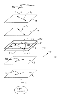
Figure 11(a) is a schematic view of the optical
components and their respective orientations of a first
embodiment of this invention. As shown in Figure 11(a)
the normally white "X-buffed" LCD (or pixel) of this
embodiment discloses a rear linear polarizer 1 provided
at the light incident side of the liquid crystal layer 5,
an exit or front linear polarizer 9 provided at the light
exit side of the liquid crystal layer 5, a rear
retardation film or plate 3 provided between the liquid
crystal layer and the rear polarizer 1, and a front
retardation film or plate 7 provided between the liquid
crystal layer 5 and the front linear polarizer 9. The
retardation films of this embodiment preferably are
uniaxial and have positive birefringent (~N) values. An
example of uniaxial positively birefringent retardation
films useful in the practice of this invention are films
commercially available from, for example, Nitto Corp.,
Japan, or Nitto Denko America, Inc., New Brunswick, New
Jersey, as Model No. NRF-RF120 (120 nm retarder).
47
2137047
In addition, biaxial retardation films are
obtainable, for example, from Allied Signal Corporation,
and negatively birefringent uniaxial/biaxial soluble
polyimide retardation films are obtainable from the
University of Akron and may also be used in certain
embodiments of this invention.
Normally incident light 11 is directed toward the
rear linear polarizer 1 from a conventional backlighting
system such as is disclosed, for example, in U.S. Patent
No. 5,161,041. The liquid crystal material 5 is
preferably of the twisted nematic type and twists at
least one normally incident visible wavelength of light
about 80 - 100 (most preferably about 90 ) as it passes
through the liquid crystal layer 5. The amount of twist
provided by the liquid crystal layer depends upon: the
wavelength of light propagating therethrough, the
thickness "d" of the liquid crystal layer 5, the
birefringence of the liquid crystal layer, and the
orientation of the rear and front buffing zones. The
liquid crystal material or layer is preferably about
4.5 - 6.0 m thick and has a birefringent value of 0.084
at room temperature.
Between the rear retardation film 3 and the liquid
crystal layer 5 is a rear orientation film 21 which has
an orientation axis or buffing zone oriented in a
direction Bi. The rear orientation film 21 oriented in
direction Bi acts to align the liquid crystal layer
48
2137047
molecules adjacent the rear orientation film in this
direction Bl. The display of Figure 11(a) is also
provided with a front orientation film 22 or buffing zone
having an orientation direction B2. The direction B 2 of
the front orientation film is preferably substantially
perpendicular to direction Bi of the rear orientation
film. As is the case with the rear orientation film, the
purpose of the front orientation film is to align the
liquid crystal molecules along the interface between the
liquid crystal layer 5 and the front orientation film in
direction B2. As described hereinafter more fully, the
rear orientation direction Bi is aligned from the lower
right to the upper left, and the front orientation
direction B2 is oriented from the upper right to the lower
left which are not to be confused with the directions of
the buffing in U.S. Patent No. 5,184,236 shown in Figure
4 herein. The effect of the alignment of these two
orientation films is to provide for a liquid crystal
layer twist of about 80 - 100 (most preferably about
90 ).
The rear linear polarizer 1 is arranged so that its
transmission axis PR is substantially parallel with the
orientation or buffing direction B2 of the front
orientation film. The front or exit linear polarizer 9
is arranged so that its transmission axis PF is
substantially perpendicular to the transmission axis PR of
the rear linear polarizer 1. Because the transmission
49
2137047
axis PR of the rear linear polarizer 1 is substantially
perpendicular to the orientation or buffing direction B,
of its adjacent orientation film 21, this defines what is
meant by "crossed" buffing (i.e. "X-buffed"). "P" (i.e.
parallel) buffing simply means that the direction of
buffing of the buffing film adjacent its respective
polarizer is parallel to the direction of polarization.
This arrangement of the transmission axes of the rear and
front polarizers also defines a twisted nematic normally
white liquid crystal display cell in that as light exits
the front linear polarizer 9, it may be viewed by a
viewer or observer 15 when the display is in the OFF
state.
This embodiment utilizes an "X-buffed" optical
arrangement because such an arrangement provides superior
results with respect to a "P-buffed" orientation.
However, a "P-buffed" arrangement could also be used in
certain other embodiments of this invention.
The rear retardation film 3, which is preferably but
not necessarily of the uniaxial type, has its optical
axis RR arranged in a direction substantially parallel to
the transmission axis PR of the rear linear polarizer 1.
Also, the optical axis RR of the rear retardation film is
arranged in a direction substantially perpendicular to
the direction Bi of the rear orientation film. The
retardation value (d = AN) of the rear retardation film 3
is preferably in the range of about 80 - 200 nm, more
2137047
preferably about 100 - 160 nm, and most preferably about
120 - 140 nm.
The front and rear retardation films are preferably
positioned about equal distances away fromYthe liquid
crystal material in this and certain other embodiments of
this invention.
The front retardation film 7, which is located on
the opposite side of the liquid crystal layer 5 as the
rear retardation film 3, is also preferably uniaxial.
The optical axis RF of the front retardation film 7 is
preferably oriented in a direction substantially parallel
to the transmission axis PF of the front or exit linear
polarizer 9. Also, the optical axis RF of the front
retardation film 7 is preferably oriented in a direction
substantially perpendicular to the orientation direction
B2 of the front orientation film. The terms
"substantially parallel" and "substantially
perpendicular" when used herein but only as used to
define the orientation of the optical axes of the rear
and front retardation films, means that the axes of the
retardation films are arranged in such a manner about
l0' unless otherwise specified.
The retardation value of the front retardation film
7 is preferably the same as that of the rear retardation
film 3. In other words, the retardation value (d - oN)
of the front retardation film 7 is in the range of about
51
~ 2137047
80 - 200 nm, more preferably about 100 - 160 nm and most
preferably about 120 - 140 nm.
The advantages of utilizing about 80 - 200 nm
retardation films according to the teachings of this
invention include a resulting larger viewing zone, and
the ability to shift the viewing zone vertically away
from an inversion area without substantially distorting
the viewing zone.
Also, the retardation values of the rear and front
retardation films are preferably about the same so as to
define a viewing zone substantially symmetrical about the
0 horizontal viewing axis. The greater the difference
between the retardation values of the retardation films 3
and 7, the greater the loss of symmetry of the viewing
zone about the 0 horizontal viewing axis. This may be
desireable in certain embodiments of this invention.
Normally incident white light 11 from a conventional
backlighting system is directed towards the normally
white liquid crystal display shown by Figure 11(a) and
toward the rear linear polarizer 1 and its transmission
axis PR The rear linear polarizer 1 linearly polarizes
the normally incident white light 11 in a direction PR.
After being polarized by the polarizer 1, the light then
proceeds toward and through the rear retardation film 3
which has a specific retardation value in the range of
about 80 - 200 nm. After being transmitted through the
rear retardation film 3 and being affected by its optical
52
CA 02137047 2003-04-22
axis RF,, the white light, then proceeds through the rear
buffing or orientation film having ari orientation
direction B, and into the liquid crystal mater-Lal S. When
proceeding through the liquid crystal material 5, the
twisted nematic materia1.. twists the normally incident white
light about 80'' - 100 , most preferably about 90 .
After exiting the .1:_quid crystal layer 5 (with its
molecules aligned along the front surface thereof in
direction B2), the light proceeds through color filters
(not shown) ancL into anr.;. through the front retardation
film 7. The color filters, may, for example, be red,
green, blue, white, or combinations thereof as shown and
discussed, for example, in U.S. Patent No. 4,632,514.
After proceeding throug~i t::he front retardation film 7 and
being affected by its o:;t.ical. axis R;j, the color filtered
light approaches the fr(_)nt polarizer 9. When the liquid
crystal display is in t:ie unenergized or OFF state (no
voltage above V,h, the threshol(d voltage, is applied
across the liquid c:ryst~a.l. material) the twisted light
proceeds through the fror,t polarizer 9 and the display
appears bright, white, c:,r colored. When the display is
in its energized or.. ON state (a voltage greater than Vtr is
applied across the liqu::..d c:rystal. material) the light
is substantially blocked to a voltage dependent extent by
the front polarizer 9 anci the display appe&rs darkened to
a viewer.
53
2137047
Electrodes provided on each side of the liquid
crystal material are conventional in the art and are not
shown in the drawings of Figures 11(a) - 11(c) for the
purpose of simplicity.
Figure 11(b) illustrates the angular relationship
between the respective axes of the polarizers,
retardation films, and orientation films of the first
embodiment of this invention. Figures 11(b) and 11(c)
are perspective views from the viewer side of the liquid
crystal display. As shown in Figure 11(b), the
transmission axis PF of the front polarizer, the optical
axis RF of the front retardation film, and the orientation
direction Bi of the rear orientation film are about
parallel one to the others. Also, the transmission axis
PR of the rear polarizer, the optical axis RR of the rear
retardation film, and the direction B 2 of the front
orientation film are also about parallel one to the
others. Therefore, an angle of about 90 is defined
between the orientations of these two groups of
directions as shown in Figure 11(b). Preferably, the
angular arrangement shown in 11(b) of the first
embodiment of this invention provides for a viewing zone
substantially symmetrical about the 0 vertical viewing
axis or reader.
The +X and +Y directions are illustrated in Figures
11(b) and 11(c), and the +Z direction comes out of the
figures toward the viewer or reader.
54
2137047
Figure 11(c) is a perspective view illustrating the
angular relationship between the above discussed optical
directions in another embodiment of this invention. In
this embodiment, the optical axes of the rear and front
retardation films 3 and 7 are symmetrically rotated
negatively so as to shift the central location of the
displays' viewing zone to a position below the 0
vertical viewing axis while substantially preserving its
shape. This embodiment of this invention illustrated by
Figure 11(c) utilizes the same parameters as those
described with respect to the first embodiment of this
invention except for the orientations of the optical axes
of the retardation films. As in the first embodiment of
this invention, the transmission axes PF and PR of the
front and rear linear polarizers in this embodiment
define an angle of about 90 therebetween. Also, the
directions Bi and B 2 are substantially perpendicular to
one another and are about parallel with the transmission
axes PF and PR of the front and rear polarizers
respectively.
The difference between the first embodiment and this
embodiment is that in this embodiment shown in Figure
11(c) the optical axis RR of the rear retardation film is
rotated so as to define an angle O1 between the
transmission axis of the rear polarizer and the optical
axis RR of the rear retardation film. Also, the optical
axis RF of the front retardation film in this embodiment
2137047
is rotated so as to define an angle e2 between the
transmission axis FF of the front polarizer and the
optical axis RF of the front retardation film.
As illustrated in Figure 11(c), the optical axis RR
of the rear retardation film is rotated clockwise
relative to directions PR and BZ, while the optical axis
RF of the front retardation film is rotated
counterclockwise relative to directions PF and Bi.
Preferably, the angles i and e2 as shown in Figure 11(c)
are substantially equal to one another thereby defining a
viewing zone for the normally white display which is
substantially symmetrical about the 0 horizontal viewing
axis. Because the optical axis RF of the front
retardation film has been rotated counterclockwise and
the optical axis RR of the rear retardation film has been
rotated clockwise to substantially equal extents, the
display of this embodiment is said to have its
retardation films rotated negatively in a symmetrical
manner. The term "symmetrical" means that the angles Ol
and 02 are substantially equal to one another. For
example, if the normally white display illustrated by
Figure 11(c) were to have its rear and front retardation
film axes "rotated -8 symmetrically," the angles Ol and
02 each would be about 4 respectively. Therefore, the
angle 8 between directions RR and RF would be about 82
when the retardation films of this embodiment were
rotated -8 symmetrically. It should then be clear that
56
2137047
if the optical axes of the rear and front retardation
films were to be rotated -4 symmetrically, the angles 6l
and e2 would each be about 2 , and the angle b between
the optical axes of the rear and front retardation films
would be about 86'.
The purpose of rotating the optical axes RR and RF of
the rear and front retardation films is to shift the
central location of the viewing zone vertically while
still substantially maintaining its shape. In the liquid
crystal display art, different customers often desire
different viewing characteristics such as the position of
the viewing zone. Because of different requirements for
different customers, it is advantageous to have a display
which may have its viewing zone shifted vertically in
accordance with a customer's needs simply by rotating the
optical axes of the rear and front retardation films. By
rotating the optical axes RR and RF of the retardation
films to a predetermined negative extent symmetrically,
the viewing zone, while being substantially maintained
with respect to shape, is shifted to a position centered
substantially below the 0' vertical viewing axis and,
therefore, away from the inversion zones present above
the 0' vertical viewing axis. Such shifts with respect
to viewing zones are disucssed and shown graphically
below with reference to this and other embodiments of
this invention.
57
2137047
Another embodiment of this invention which is
related to the embodiment 6isclosed ir. Figure 11(c) is
the situation where the optical axes of the rear and
front retardation films are rotated to a predetermined
positive value symmetrically. When the optical axes RR
and RF are rotated, for example, +6 symmetrically, the
optical axis RR is rotated 3 counterclockwise relative to
directions PR and BZ, while retardation axis RF is rotated
3 clockwise relative to directions Bi and PF. Therefore,
the rear and front retardation optical axes RR and RF
define angles 01 and 2 of about 3 between their axes
and the transmission axes of their respective adjacent
polarizers. In this situation where the optical axes RR
and RF are rotated +6 symmetrically, the angle S is about
96 . When the optical axes of the retardation films are
rotated in a positive manner symmetrically, the result is
a shifting of the viewing zone to a position centered
substantially above the 0 vertical viewing axis.
Figures 12 - 25 are computer simulations of the
first embodiment of this invention illustrating the
effect of different driving voltages, retardation values,
and wavelengths.
Figures 12 and 13 are computer simulation contrast
ratio curve graphs of the first embodiment of this
invention when the red wavelength of 630 nm is used.
With respect to Figures 12 and 13, the cell gap "d" is
5.70 m, and the optical axes RR and RF of the rear and
58
2137047
front retardation films are parallel to the transmission
axes of the rear and front linear polarizers
respectively. The rear and front retardation films 3 and
7 each have retardation values of 120 nm in the computer
simulation graphs of these F'_gures, as well as Figures 14
- 19.
In Figure 12, VoN was 6.8 volts and V OFF was 0.9
volts. As can be seen in Figure 12, the contrast ratios
of the red wavelength are extremely good, especially
horizontally. The 30:1 contrast ratio curve extends off
the graph in both horizontal directions, while the 10:1
contrast ratio curve extends off the graph in the
positive vertical direction. The 30:1 contrast ratio
curve extends along the 0 vertical viewing axis a total
of about 110 from about -55 to +55 horizontal.
Furthermore, the 50:1 contrast ratio curve along the 0
vertical viewing axis extends from about -46 to +46'.
These are significant improvements over the prior art.
Figure 13 is a contrast ratio curve graph which used
as parameters those described above with respect to
Figure 12 except that VoN was 6.0 volts. As can be seen
in Figure 13, by lowering the parameter VoN, or driving
voltage, the viewing zone is diminished vertically and is
slightly shifted upward in the positive vertical viewing
direction. However, when, in Figure 13, the driving
voltage is 6.0 volts, the 50:1 contrast ratio curve
59
2137047
extends along the 0 vertical viewing axis to extents of
about 55 horizontal.
Figures 14 - 15 are computer simulation contrast (or
contour) ratio curve graphs utilizing the green
wavelength of 550 nm in the display of the first
embodiment of this invention. The cell gap "d" with
respect to Figures 14 - 15 was 5.70 m and the rear and
front retardation films 3 and 7 had retardation values of
120 nm. Figure 14 illustrates the case where VoN was 6.8
volts while Figure 15 had a VoN of 6.0 volts. As shown in
Figure 14, the 50:1 contrast ratio curve extends
horizontally along the 0 vertical viewing axis a total
of about 90 from horizontal angles of about -45 to
+45'. As can be seen in Figure 15, by decreasing the
driving voltage the viewing zone is constricted slightly
vertically and is shifted upward to a position centered
substantially above the 0' vertical viewing axis.
Figures 16 - 17 are computer simulation contrast
ratio curves of the first embodiment of this invention
when the blue wavelength of 480 nm was used and the rear
and front retardation films had retardation values of 120
nm. In Figures 16 - 17, the cell gap was also 5.70 m.
As was the case with respect to the red and green
wavelengths, when VoN is decreased from 6.8 volts (Figure
16) to 6.0 volts (Figure 17), the viewing zone shifts
upward substantially above the 0 vertical viewing axis
2137047
and shrinks vertically with respect to the overall
vertical angles covered by the 10:1 contrast ratio curve.
Figure 18 is a driving voltage versus transmission
graph illustrating the transmission at various driving
voltages in a range of horizontal viewing angles (-60 to
+60 ) along the 0 vertical viewing axis. With the
exception of the 60 curves, there is substantially no
effect of inversion upon these transmission versus
driving voltage curves throughout the gray level driving
voltage zones of about 2 - 6 volts. In other words,
throughout the gray level driving voltage zones, when the
driving voltage is increased, the transmission is
decreased accordingly, thus, providing for good gray
level performance along the 0 vertical viewing axis
throughout the horizontal angles shown and defined in
Figure 18. One needs simply to compare the graph of
Figure 18 with the graph of prior art Figure 3 to see
that the arrangements of the optical parameters of the
first embodiment of this invention decrease the effect of
inversion upon various horizontal viewing angles and
provide for an improved gray level performing NW liquid
crystal display.
The curves of Figure 19 representing different
vertical viewing angles along the 0 horizontal viewing
axis have transmission percentages which generally
diminish with increases in driving voltage, possibly with
the exception of the +40 vertical viewing angle. The
61
2137047
effect of inversion is only seen with respect to the
vertical viewing angles of +30 to +40 . In other words,
throughout a wide range of gray level driving voltages,
when the voltage is increased the transmission is
decreased accordingly thus providing for excellent gray
level performance throughout the vertical range. The
cell gap in Figures 18 - 19 was 5.70 m. It is noted
that white light was used in plotting the driving voltage
versus transmission curves of Figure 18 and Figure 3.
The large inversion humps present in Figure 3 do not
appear in Figures 18 - 19, thus, illustrating an
improvement of this embodiment over the prior art.
Figures 20 - 22 are computer simulation contrast
ratio curve graphs of the first embodiment of this
invention when the rear and front retardation films 3 and
7 had retardation values of 160 nm, VoN was 6.8 volts, and
the cell gap "d" was 5.70 m.
Figure 20 illustrates the case where the red
wavelength of 630 nm was used. In comparing the case
where the LCD of the first embodiment utilized 160 nm
retardation films (Figure 20) with the case where 120 nm
retardation films (Figure 12) were used, the difference
is that when rear and front retardation values of 120 nm
were used the contrast ratios extended to further extents
in both the horizontal and vertical directions. For
example, with respect to the red wavelength of 630 nm
shown in Figure 12 (120 nm retardation films) and Figure
62
2137047
20 (160 nm retardation films) the 50:1 contrast ratio
curve in Figure 12 extended horizontally a total of about
110 from about -55 horizontal to about +55 horizontal,
while in contrast to this, 50:1 contrast ratio curve in
the 160 nm case (Figure 20) extended horizontally to
angles of about 45'. However, the boomerang shape of
the viewing zone shown in Figure 12 was substantially
eliminated when the 160 nm retardation films were used as
shown in Figure 20. Also, the 30:1 contrast ratio curve
in Figure 20 extended in some places to extents further
than that of the 30:1 curve of Figure 12. In sum, both
cases, one with retardation films of 120 nm and the other
with retardation films of 160 nm, exhibited excellent
results in that their respective viewing zones extended
to large horizontal and vertical viewing angles.
Figure 21 illustrates the case where the green
wavelength of 550 nm was used in the first embodiment of
this invention and the rear and front retardation films 3
and 7 had retardation values of 160 nm. This graph shows
that the use of 160 nm retardation films in the first
embodiment of this invention provided a viewing zone
which extended to large viewing angles in both the
horizontal and vertical directions.
Figure 22 illustrates the case where the blue
wavelength of 480 nm was used in combination with 160 nm
retardation films. In the cases where 160 nm retardation
films were used, the viewing zones were diminished
63
2137047
slightly with respect to the 120 nm cases, however, the
contrast ratio curves are still excellent.
Figures 23 - 25 are computer simulation contrast
ratio curve graphs of the first embodiment of this
invention when the rear and front retardation films 3 and
7 had retardation values of 80 nm, VoN was 6.8 volts, and
the cell gap "d" was 5.70 m. Figure 23 illustrates the
case where a red wavelength of 630 nm was used. Figure
24 illustrates the case where the green wavelength of 550
nm was used, and Figure 25 illustrates the case where the
blue wavelength of 480 nm was used. Figures 23 - 25 all
represent excellent contrast ratio curves for the first
embodiment of this invention when retardation values of
80 nm were used. The displays of Figures 12 - 25 all
utilized uniaxial positively birefringent retardation
films.
This invention will now be described with respect to
certain examples as follows:
EXAMPLE 1
In this first example, an "X-buffed" light valve
having a cell gap "d" of 5.86 m and a liquid crystal
birefringence (AN) of 0.084 at room temperature was
manufactured and tested as follows. The liquid crystal
material used is available commercially from E. Merck
Ltd. or its U.S. representative EM Industries, Inc.,
Hawthorne, New York as Model No. ZL14718. Data resulting
64
2137047
from the light valve of this example is illustrated in
Figures 26 - 30.
The light valve pixel of this example was similar to
the first embodiment of this invention in that the rear
linear polarizer had a transmission axis direction about
parallel to the optical axis of the rear retardation
film, and the optical axis of the front retardation film
was about parallel to the transmission axis of the front
or exit linear polarizer. The orientation or buffing
direction of the rear orientation film was approximately
perpendicular to the optical axis of the rear retardation
film, and was approximately parallel to the optical axis
of the front retardation film. The optical axes of the
rear and front retardation films defined an angle 8 of
about 90 therebetween. The orientation direction of the
front orientation film was approximately parallel to the
direction of the optical axis of the rear retardation
film, and was substantially perpendicular to the
direction of the rear orientation film. White light (RGB
tri-peaked) was used when testing the light valve of this
example (see Figures 26 - 30). The rear and front
retardation films were of the uniaxial type and had
positive birefringent values. Also, the rear and front
retardation films both had retardation values of 120 nm.
The temperature was about 35 - 40 C.
Figure 26 illustrates the experimental data when the
driving voltage VoN was 6.8 volts and VOFF was 0.2 volts
2137047
for this example. As can be seen, the 10:1 contrast
ratio curve extends horizontally along the 0 vertical
viewing axis to about 50 horizontal thereby defining a
total horizontal viewing range along the 0 vertical
viewing axis of about 100 . This 100 range is to be
compared with the about 77 range shown in prior art
Figure 1, and the about 65 horizontal range shown in
prior art Figure 5D. In other words, the 10:1 contrast
ratio curve of this example at 6.8 volts is substantially
improved over displays and light valves of the prior art.
In this respect, it is also to be noted that the 50:1
contrast ratio curve shown in Figure 26 extends along the
0 vertical viewing axis a substantial distance, i.e.
over a total angular span of about 75'.
Figure 27 illustrates the case where VON was 6.0
volts for the normally white light valve of this first
example. When VoN is decreased from 6.8 volts to 6.0
volts, a more realistic VoN was applied to the pixel and
the 10:1 contrast ratio curve extended horizontally
slightly further than that shown in Figure 26.
Figure 28 illustrates the case where VoN was
decreased to 5.0 volts for the light valve of this first
example. In the case where 5.0 volts was applied to the
pixel, the 10:1 contrast ratio curve defines a range of
about 112 along the 0 vertical viewing axis. This is
significantly greater than the range defined by the 10:1
66
2137047
contrast ratio curves of the prior art described and
illustrated herein.
Figure 29 illustrates the case where VON was 4.0
volts for the light valve of this first example. When
4.0 volts was applied to the pixel the 10:1 contrast
ratio curve substantially extends off the graph in both
horizontal directions. However, when the voltage is
decreased, as is the case in Figure 29, the viewing zone
shrinks vertically and is shifted slightly upward, a
condition generally true with regard to each of the
illustrated decreases in voltage.
Figure 30 is an intensity versus driving voltage
plot for this example illustrating the effects of gray
level driving voltages for different horizontal viewing
angles ranging from -60 to +60 along the 0 vertical
viewing axis. As can be seen in Figure 30, the gray
level performance of this pixel is very good in that the
inversion humps are relatively small or non-existent for
a wide range of horizontal viewing angles defined herein.
In other words, the horizontal gray level performance of
this light valve is good because as the driving voltage
increases, the intensity for the most part decreases
accordingly. Therefore, when the driving voltage of this
pixel is increased from one gray level voltage to another
the intensity of the pixel generally decreases. The
improved results illustrated in the graph shown in Figure
are to be compared to the inferior results illustrated
67
2137047
in the prior art graph, Figure 3, where the inversion
humps which begin at about 3.2 volts are relatively large
and extend up into the range substantially over 200 fL.
In short, the gray level characteristics of the light
valve of this example are significantly improved over
those of the prior art.
EXAMPLE 2
In this second example, a multi-colored liquid
crystal display utilizing TFTs as switching devices in an
active matrix array was constructed as follows. The
normally white "X-buffed" liquid crystal display had a
cell gap "d" of about 5.1 m for the red subpixel which
included a red color filter, and a cell gap "d" of about
5.7 m for the green and blue subpixels which included
green and blue color filters respectively. The
difference in cell gap for the different subpixels was
due to the different thicknesses of the color filters.
The birefringence of the LC material was 0.084 at room
temperature. The liquid crystal material was purchased
from Merck, Model No. ZL14718. The display had a rear
linear polarizer having a transmission axis substantially
perpendicular to the transmission axis of the front or
exit linear polarizer. A rear retardation film having an
optical axis about parallel to the transmission axis of
the rear polarizer was sandwiched between the rear
polarizer and the liquid crystal material. Likewise, a
68
2137047
front retardation film having an optical axis about
parallel to the transmission axis of the front polarizer
was disposed between the front polarizer and the liquid
crystal material. A rear orientation film was provided
with an orientation direction about perpendicular to the
optical axis of the rear retardation film, and about
parallel to the transmission axis of the front polarizer.
A front orientation film was provided with an orientation
direction substantially parallel to the transmission axis
of the rear polarizer, and about perpendicular to the
optical axis of the front retardation film.
The optical axes of the rear and front retardation
films defined an angle S of about 90 therebetween. The
rear and front retardation films both had retardation
values of 120 nm. The front and rear retardation films
both had positive birefringent values and were of the
uniaxial type purchased from Nitto Denko Amgrica
Corporation, New Brunswick, New Jersey*. White light was
used in testing this display and the measured results are
reported in Figures 31 - 35.
Figure 31 illustrates the contrast ratio curves when
a V ON of 6.8 volts was applied to this normally white
liquid crystal display. As can be seen, the 10:1
contrast ratio curve extends horizontally along the 0
vertical viewing axis a total of at least about 120'.
This range is significantly greater than the ranges
defined by the 10:1 contrast ratio curves of the prior
69
2137047
art discussed above. Likewise, the 30:1 contrast ratio
curve of Figure 31 extends along the 0 vertical viewing
axis to horizontal angles of about 42 horizontal. The
10:1 contrast ratio curve of this example when 6.8 volts
was applied to the display extends vertically alorig the
0 horizontal viewing axis from about -40 to about +35
vertical. Again, this range defined vertically by the
10:1 contrast ratio curve of this example is
significantly improved over that of the prior art.
Figure 32 illustrates the situation where 6.0 volts
was applied to the normally white liquid crystal display
of this example. As can be seen in Figure 32, when 120
nm retardation films are used and 6.0 volts is applied to
the display, the 10:1 contrast ratio curve still extends
at least a total of about 120 horizontally along the 0"
vertical viewing axis. This liquid crystal display
clearly exhibits excellent contrast ratio curves over
very wide ranges of viewing angles.
Figure 33 illustrates the situation where 5.0 volts
was applied to the display of this example. As shown the
10:1 contrast ratio curve still extends at least a total
of about 120 horizontally along the 0 vertical viewing
axis when 5.0 volts was applied to the display. The
viewing zone, as previously discussed, decreases
vertically as the voltage drops.
Figure 34 illustrates the situation where 4.0 volts
was applied to the display of this example. Again, the
2137047
10:1 contrast ratio curves still extends off the graph
horizontally along the 0 vertical viewing axis defining
a range of at least about 120 . Taken together, Figures
31 - 34 illustrate that the inventive normally white
display of this example, has excellent contrast ratios
over a wide range of driving voltages, especially in the
horizontal directions.
Figure 35 is a driving voltages versus intensity
plot for the display of this example when white light was
used. This plot is for a range of horizontal viewing
angles extending from -60 to +60 along the 0 vertical
viewing axis. As shown, there is virtually no inversion
at any voltage for the various horizontal viewing angles
defined therein. In other words, as the gray level or
driving voltages increase, the intensity of light emitted
from the display decreases in conjunction therewith,
thus, providing excellent gray level performance for"the
display of this example. The plot of Figure 35 when
compared with that of Figure 3 highlights how the LCDs of
this invention virtually eliminate the inversion humps
experienced in the prior art, which allows the displays
of this invention to be satisfactorily used throughout a
wide range of gray level voltages.
EXAMPLE 3
An "X-buffed" normally white liquid crystal display
was constructed having a cell gap of 5.1 m for the red
71
2137047
subpixel including a red color filter, and 5.7 m for the
green and blue subpixels including green and blue.color
filters respectively. The AN of the liquid crystal
material was 0.084 at room temperature. The liquid
crystal material was Merck's Mode No. ZL14718. This
liquid crystal display was driven by a conventional TFT
active matrix array.
The normally white display included a rear
polarizer, a rear retardation film, a rear substrate, a
rear electrode, a rear orientation film, a liquid crystal
layer, a front orientation film, a front electrode, a
front substrate, a front retardation film, and a front or
exit polarizer in that order. The transmission axis of
the rear polarizer was approximately parallel to the
optical axis of the rear retardation film and the
orientation direction of the front orientation film. The
transmission axis of the front polarizer was
approximately parallel to the optical axis of the front
retardation film and the orientation direction of the
rear orientation film. The optical axes of the rear and
front retardation films defined an angle of about 90
therebetween. The retardation values for both the rear
and front films was 120 nm. The rear and front
retardation films were of the uniaxial type and had
positive birefringent values.
Figure 36 illustrates the contrast ratio curves for
this example when white light was applied to the display
72
2137047
and a driving voltage of 6.0 volts was applied. As can
be seen, the 10:1 contrast ratio curve extends along the
0 vertical viewing axis to horizontal angles of at least
about 60 . Also, the 30:1 contrast ratio curve of this
example when 6.0 volts was applied to the display extends
along the 0 vertical viewing axis to horizontal angles
of about 44 . These are significant improvements over
the prior art. Also, the 10:1 contrast ratio curve as
shown in Figure 36 extends along the 0 horizontal
viewing axis to vertical angles of about 33 . White
light was used in obtaining the data generated by this
graph.
EXAMPLE 4
In this example a normally white "X-buffed" light
valve according to this invention was constructed wherein
the optical axes of the rear and front retardation films
were rotated -8 symmetrically thereby shifting the
viewing zone to a position centered substantially below
the 0 vertical viewing axis while maintaining its shape
or integrity.
In this example, the light valve was constructed as
follows. A rear linear polarizer was provided with a
transmission axis PR defining a first direction. A front
linear polarizer was provided having a transmission axis
PF defining a second direction substantially perpendicular
to the first direction. The orientation of the rear
73
2137047
orientation film was substantially parallel to the second
direction defined by the transmission axis PF of the front
polarizer. The orientation direction of the front
orientation film was substantially parallel to the
transmission axis direction defined by the transmission
axis PR of the rear polarizer.
A rear retardation film of the uniaxial type having
a positive birefringent value was disposed between the
rear polarizer and the rear orientation film. A front
retardation film of the uniaxial type having a positive
birefringent value was provided between the front
polarizer and the front orientation film.
Because the optical axes of the rear and front
retardation films were rotated -8 symmetrically, angles
01 and 92 were 4 respectively with an angle S of 82
defining the angle between the optical axes of the rear
and front retardation films. In other words, the optical
axis RF of the front retardation film was rotated 4
counterclockwise relative to the transmission axis PF of
the front polarizer. Also, the optical axis RR of the
rear retardation film was rotated clockwise 4' relative
to the transmission axis PR of.the rear linear polarizer.
Accordingly, the axes of the rear and front retardation
films defined an angle of 82' therebetween represented by
the angle b in Figure 11(c).
The rear and front retardation films of this example
had retardation values of 120 nm. The liquid crystal
74
2137047
material was Model No. ZL14718 from E. Merck Ltd. The
cell gap "d" of a liquid crystal layer was 5.86 m for
the light valve pixel of this example and the LC
birefringence was 0.084. The temperature in this
example, as in all of the other examples discussed
herein, was about 35 C - 40 C unless otherwise specified.
Figure 37 is a contrast ratio curve graph
illustrating the viewing zone of the light valve of this
example when 6.8 volts and white light was applied
thereto. As can be seen, the viewing zone is centered at
a position about 10 below the 0 vertical viewing axis
(i.e. at about the -10 vertical viewing axis) as a
result of the -8 symmetrical rotation of the optical
axes of the rear and front retardation films.
This example illustrates the situation where the
viewing zone of a display or pixel is shifted to a
position substantially below the 0 vertical viewing axis
while still substantially maintaining the integrity or
symmetry of the overall viewing zone. The symmetry of
the viewing zone about the 0 horizontal viewing axis is
substantially maintained because the rear and front
retardation films had substantially equal retardation
values.
Figure 38A illustrates the viewing zone of the light
valve of this example when 5.0 volts and white light was
applied thereto. As can be seen in Figure 38A, the
viewing zone is still centered about the -10 vertical
2137047
viewing axis and is provided with excellent contrast
ratios at large viewing angles. As a result of the
decrease on VoN from 6.8 volts to 5.0 volts, it is seen in
Figure 38A that the viewing zone has been slightly
constricted vertically and slightly expanded horizontally
about the center of the viewing zone.
The advantage associated with the light valve of
this example is that the centered position of the viewing
zone of a given liquid crystal display or pixel thereof
according to certain embodiments of this invention can be
shifted vertically from one position to another while
substantially maintaining the symmetry of the viewing
zone in accordance with the specific needs of different
customers. These shifts of the viewing zone are
accomplished by simple rotation, preferably
symmetrically, of the optical axes of the rear and front
retardation films of certain embodiments of this
invention.
Figure 38B illustrates the inversion hump problem
associated with the vertical viewing angles above the 0
vertical viewing axis for the display of this example.
The viewing zone of the display of this example is
centered at a location below the 0 vertical viewing axis
remote from these inversion areas illustrated in Figure
38B. Thus, gray level performance is improved by
centering the viewing zone at a position distant the
76
2137047
inversion zone thereby limiting inversion effects to
remote viewing angles.
EXAMPLE 5
A multi-colored nornally white "X-buffed" liquid
crystal display was constructed and tested with white
light as follows. The display, including a conventional
TFT matrix array, included a rear linear polarizer having
a transmission axis defining a first direction, a front
or exit linear polarizer having a transmission axis
defining a second direction wherein the first and second
directions were substantially perpendicular to one
another, a rear retardation film between the rear
polarizer and the liquid crystal layer and having an
optical axis substantially parallel to the transmission
axis of the rear polarizer, a front retardation film
having an optical axis substantially parallel to the
transmission axis of the front polarizer, a rear
orientation film having an orientation direction
substantially perpendicular to the first direction
defined by the transmission axis of the rear polarizer, a
front orientation film having an orientation direction
substantially perpendicular to the transmission axis of
the front polarizer, and finally a liquid crystal layer
sandwiched between the orientation films. The rear and
front retardation films had positive birefringent values
and were of the uniaxial type. Furthermore, the rear and
77
2137047
front retardation films each had a retardation value of
120 nm.
The optical axes of the rear and front retardation
films were rotated -3 symmetrically. Therefore, with
reference to Figure 11(c), angles el and e2 were each
1.5 , and angle b was 87 in the display of this example.
Figure 39 is a white light contrast ratio curve
graph showing the measured results when the liquid
crystal display of this example had a voltage of 6.0
volts applied to the active matrix, VOFF was 0.2 V. and
VCOMM was 8.14 V. The contrast ratios as shown in Figure
39 are excellent in that the 10:1 contrast ratio curve
extends significantly beyond a horizontal range of 120
along the 0 vertical axis. Furthermore, the 30:1
contrast ratio along the 0 vertical viewing axis defines
a total range of about 100 which is significantly more
than that of the prior art. The 10:1 contrast ratio
curve in the vertical direction covers a range along the
0 horizontal viewing axis of between about -20 vertical
and at least about 40 vertical.
As can be seen in Figure 39, the -3 symmetrical
rotation of the retardation films was not enough to shift
the viewing zone below the 0 vertical viewing angle
axis. This may be due to manufacturing derivations
associated with certain optical elements of this display.
Nevertheless, the viewing zone and contrast ratios are
excellent, both horizontally and vertically.
78
2137047
The cell gap "d" of the display manufactured in this
example was 5.1 m in the red subpixel whero a red color
filter was provided, and 5.7 m in both the green and
blue subpixels where green and blue color filters were
provided respectively. The difference in cell gap "d"
between the subpixels is a result, as in the other
examples herein, of the different thicknesses of the
color filters. In other words, because the red color
filter has a thickness greater than the green and blue
color filters, the cell gap "d" in the red subpixel is
less than that in the green and blue subpixels. The LC
material birefringence was 0.084 at room temperature.
The left handed liquid crystal material was Merck's Model
No. ZLI4718.
EXAMPLE 6
In this example, an "X-buffed" NW light valve pixel
was constructed and tested using white light. A rear
linear polarizer was provided having a transmission axis
defining a first direction and a front linear polarizer
was provided having a transmission axis defining a second
direction wherein the first and second directions were
substantially perpendicular to one another, thus,
defining a normally white light valve. A rear
retardation film having an optical axis approximately
parallel to the transmission axis of the rear polarizer
was provided between the rear polarizer and a rear
79
2137047
orientation film. The rear orientation film had a
buffing or orientation direction substantially parallel
to the direction defined by the transmission axis of the
front polarizer. A front retardation film having an
optical axis about parallel to the transmission axis of
the front polarizer was disposed between the front
polarizer and a front orientation film. The front
orientation film had an orientation or buffing direction
substantially perpendicular to that of the rear
orientation film.
In this example, the rear and front retardation
films were of the biaxial type. Biaxial retardation
films can be characterized by two separate retardation
values: d- oZX and d- o ZY. The local X optical axes of
the rear and front biaxial retardation films in this
light valve were oriented about parallel to their closest
adjacent polarizer transmission axis. The local X axis
of a biaxial retardation film herein means the axis in
the direction having the highest index of refraction (nX
is always the largest index of refraction and nZ is the
lowest). The X, Y, and Z directions (axes) of the
biaxial retardation films herein are separate and
distinguished from the X, Y, and Z directions (Figure 6)
of the display. In this example, the axis having the
retardation value of d=A ZX =-168 nm had the highest or
largest index of refraction. Both the rear and front
biaxial retardation films were obtained from Allied
2137047
Signal Corporation as Sample No. 4Ø The indices of
refraction of the biaxial retardation films of this
example were nX = 1.4305; nY = 1.4275; and nZ = 1.4261.
The liquid crystal material had a birefringence of 0.084
at room temperature and was Merck's Model No. ZL14718.
The films therefore had retardation values d-AZx = -168
nm and d - AZY =-53.3 nm.
Figure 45 is a contrast ratio curve graph
illustrating the measured results of the light valve of
this example. In Figure 45, VoN was 6.0 V and VOFF was 0.2
V. As shown, the 10:1 contrast ratio curve extends
horizontally off the graph along the 0 vertical viewing
axis, thus, defining a horizontal viewing range of
greater than about 120 . Furthermore, the 30:1 contrast
ratio curve defines a total viewing range along the 0
vertical viewing axis of about 95 - 100 . This is a
significant improvement over the prior art. The 10:1
contrast ratio curve in the vertical direction along the
0 horizontal viewing axis covers a range of about 75 .
This example illustrates that when a light valve
according to this invention is provided with biaxial rear
and front retardation films, excellent viewing zone and
contrast ratios result and constitute a significant
improvement over the prior art.
81
2137047
EXAMPLE 7
Figure 40 is a computer simulation contrast ratio
curve graph illustrating a simulated liquid crystal
display according to another embodiment of this invention
where the optical axes of the rear and front retardation
films are rotated +4 symmetrically. Due to this
positive rotation, the center of the viewing zone is
shifted to a position substantially above the 0" vertical
viewing axis. As shown, the viewing zone of.this display
is centered about the +20 vertical viewing axis because
of the +4 symmetrical rotation of the retardation films.
With reference to Figure 11(c), the axis RF of this
embodiment is rotated or oriented clockwise relative to PF
and Bi defining an angle of 2 therebetween. Also, axes
RR of this embodiment is oriented counterclockwise 2
relative to PR and BZ. As a result, the angle b between
the optical axes of the retardation films is- 94' due to
the +4 symmetrical rotation of the retardation film
axis. The display of this embodiment would be desirable
in situations where a viewing zone centered above the 0
vertical viewing axis was desired. The simulation of
Figure 40 used a VoN of 6.8 V, a green wavelength of 550
nm, and 160 nm retarders. The transmission axes of the
polarizers as opposed to the optical axes of the
retardation films may instead be rotated to shift the
location of the viewing zone in certain other embodiments
of this invention. However, rotation of the polarizer
82
2137047
axes does not provide as good of results as does the
rotation of the retarder axes.
EXAMPLE 8
Figure 43 is a computer simulation of a liquid
crystal display according to yet another embodiment of a
NW "X-buffed" LCD of this invention. This embodiment is
similar to that illustrated and described in the first
embodiment of this invention except that the rear and
front retardation films 3 and 7 are negatively
birefringent and uniaxial. The optical axes of these
retardation films are oriented in the "Z" direction, or
in other words, in a direction approximately
perpendicular to the planes defined by the retardation
films. The display of this embodiment, simulated by
Figure 43, had a cell gap of 5.70 m, utilized a
wavelength of 550 nm in testing the display, a VaN of 6.0
volts, was "X-buffed," and a temperature of about 30 C.
The rear and front retardation films of this
embodiment had retardation values of d- A ZX = d =~ ZY =
-160 nm. These films are "uniaxial" because dAZX =
d- AZY. The retardation value d= A ZX is defined as
meaning d - (nZ - nX) where "n" is the index of refraction
of a particular axis and "d" is the thickness of the
retardation film. The retardation films of this
embodiment were negative because the parameter nx was
greater than the parameter nZ. The X, Y, and Z directions
83
2137047
of the biaxial retardation films herein are separate and
distinguished from the X, Y, and Z directions defining
the coordinates of the display.
The term nX herein always represents the largest
5'index of refraction, and nZ always represents the
smallest. The rear and front polarizers had transmission
axes which are substantially perpendicular to one
another. The rear retardation film was disposed between
the rear polarizer and the rear orientation film, and the
front retardation film is between the front polarizer and
the front orientation film. The negatively birefringent
uniaxial retardation films of this embodiment are
obtainable from the University of Akron and are disclosed
in U.S. Patent No. 5,071,997 as soluble polyimides and/or
copolyimides.
As can be seen in Figure 43, this embodiment
achieves outstanding contrast ratios at very large
viewing angles. For example, the 50:1 contrast ratio
curve on the 0 vertical viewing axis defines a range of
almost 100 horizontally. This is a significant
improvement over the prior art.
EXAMPLE 9
Figure 44 is a computer simulation contrast ratio
graph of another NW embodiment of this invention which
utilizes biaxial front and rear retardation films each
having retardation values d- oZX =-160 nm and d=11~Y =
84
2137047
-60 nm. Because the retardation values are negative, the
films have negative birefringence. d- oZX is defined as
d - (nZ - nX) wherein nX is the largest index of
refraction in the film and nZ is the smallest. Therefore,
d=A ZX is always the largest retardation value herein.
The graph of Figure 44 was plotted using the parameters
of VoN = 6.0 volts, a LC birefringence of 0.084, a VOFF of
0.9 V, a cell gap of 5.70 m, a temperature of about
30 C, an "X-buffed" configuration, and a wavelength of
550 nm. The local X' is the axis with the largest index
of refaction, or nX. The local X' optical axis of each
retardation film is oriented substantially parallel to
the adjacent polarizer transmission axis. In other
words, the local X' axis of the rear retardation film is
substantially parallel to the transmission axis of the
rear polarizer, and the local X' optical axis of the
front biaxial retardation film is substantially parallel
to the front polarizer transmission axis. The local X'
optical axis in this embodiment has the aforesaid
retardation value of d- A Zx = -160 nm, because nX was the
largest index of refraction. The rear and front
polarizer axes define an angle of about 90 therebetween.
The axis with the smallest index of refraction, or nZ, is
oriented about perpendicular to the planes defined by the
retardation films. As shown in Figure 44, the embodiment
of this invention using the aforesaid biaxial retardation
films achieves excellent contrast ratios at large viewing
2137047
angles. Again, the 50:1 contrast ratio curve along the
0 vertical viewing axis defines a range of about 100
horizontally.
The specific electrodes and substrates present in
the displays and light valves of the above described
examples are conventional and were not described or shown
for purposes of simplicity.
Figure 41 is a cross-sectional view of the
structural arrangement of a typical liquid crystal
display pixel envisioned by this invention. For example,
the optical arrangement shown and described in Figures
11(a) - 11(c) may be used in conjunction with the
structural arrangement shown in Figure 41. Normally
incident light enters the pixel and first proceeds
through rear linear polarizer 1 and is polarized thereby.
After proceeding through the polarizer 1, the normally
incident light proceeds through the rear retardation film
3 and the rear transparent substrate 19. The transparent
substrates 19 and 20 are preferably made of glass, but
also may be made of plastic, quartz, or the like. After
proceeding through the rear transparent substrate 19, the
light then enters the lower pixel electrode 24 and passes
therethrough without being substantially optically
affected. The light then proceeds through the rear
86
2137047
orientation film 21, a liquid crystal layer 5, the front
orientation film 22, and the front electrode layer 25.
After proceeding through electrode 25, the light then
propagates through the front transparent substrate 20,
front retardation film 7, and finally comes to the front
or exit linear polarizer 9. When the pixel is in the OFF
state, the light proceeds through the linear polarizer 9
toward a viewer. However, when the pixel is in the ON or
energized state, the exit polarizer 9 absorbs the light
of the pixel and the display appears darkened. Also,
color filters (not shown) may be provided at any point
between the transparent substrates, and preferably
between the front substrate 20 and the electrode layer 25
thereby creating a multicolored pixel including a
plurality of colored subpixels. It is understood, of
course, that retardation films 3 and 7 may also serve as
the buffing layers. In such an embodiment films 3 and 7
are replaced and relocated into the location of buffing
films 21 and 22 respectively. It is further understood
that retarder films 3 and 7 when not replacing buffing
films 21 and 22 may be relocated so as to be between
their respective driving electrode (24 and 25) and glass
substrate (19 and 20) respectively. By arranging the
optical elements of this structural arrangement (Figure
41) as taught by certain optical embodiments of this
invention, the aforesaid improved contrast ratios over
predetermined ranges of viewing angles may be achieved.
87
CA 02137047 2003-04-22
An alternative structural arrangement envisioned by
this invention, is a normally white pixel similar to the
one shown in Figure 41, except that the rear and front
retardation films 3 and 7 are disposed between the
substrates 19 and 20. The rear retardation film is
sandwiched between, for example, the rear substrate 19
and the rear electrode 74,, and the front retardation film
is disposed between the front substrate 20 and the front
electrode 25. All embodiments of this invention may be
practiced in such a structural arrangement with excellent
contrast ratios over a large range of viewing angles
being realized.
Furthermore, the retardation films according to
certain embodiment of this invention may be personalized
or patterned acc.,ordi.ng to the wavelength or color of each
subpixel as taucht by our commonly owned U.S. Patent No.
5,499,126. In other words, a retardation film within a
red subpixel may have a retardation value different than
a retardation film in a green or blue subpixel.
Figure 42 is a partial cut-away view of a typical
active matrix liquid cryt,tal pixel array as envisioned by
this invention. Herein, the rear and front retardation
films, which are not specificalLy shown in Figure 42, are
88
2137047
sandwiched between their adjacent polarizers 1 and 9, and
their adjacent_substrates 19 and 20. The individual
pixels 30 shown in Figure 42 are driven by conventional
TFTs 31 which act as switching devices to selectively
drive each pixel 30. Conventional transparent ITO
electrodes 33 connect the individuals TFTs 31 to their
respective pixels 30. Parallel conductive row lines 35
drive either the gate or drain electrodes of the TFTs 31.
Column lines 37 drive the other of the gate and drain
electrodes of a TFTs thereby selectively driving the
individual pixels 30 when a specific TFT has both its
gate and drain electrodes energized.
The simulations, light valves, and displays of
Figures 7 - 45 herein were twelve o'clock buffed.
Therefore, the rear orientation or buffing directions
went from the lower right to the upper left, and the
front orientation or buffing direction went from the
upper right to the lower left.
The pretilt angle of the displays, light valves, and
simulations of Figures 1 - 3 and 7 - 45 herein is about
3 , and the value of "d/p" (thickness/natural pitch of
the liquid crystal material) of the liquid crystal layer
of these Figures is set to about 0.25.
The computer simulations herein were conducted using
simulation software written by Dr. Dwight Berreman,
Scotch Plains, New Jersey. The software is described and
referenced in one of Dr. Berreman's publications titled
89
2137047
"Numerical Modelling of Twisted Nematic Devices," Phil.
Trans. R. Soc. Lond. A309, 203-216 (1983) which was
printed in Great Britain.
Once given the above disclosure, many other
features, modifications, and improvements will become
apparent to the skilled artisan. Such other features,
modifications, and improvements are, therefore,
considered to be a part of this invention, the scope of
which is to be determined by the following claims: