Note: Descriptions are shown in the official language in which they were submitted.
2137207
TRANSPARENT FUNCTIONAL MEMBRANE CONTAINING
FUNCTIONAL ULTRAFINE PARTICLES, TRANSPARENT
FUNCTIONAL FILM, AND PROCESS FOR PRODUCING THE SAME
BACKGROUND OF THE INVENTION
The present invention relates to a transparent
functional membrane wherein functional ultrafine
particles having various functions, such as a UV
screening effect, an antistatic effect, and an
antireflection effect, are localized in a coating,
particularly localized and fixed in a coating on its
surface layer in contact with or near air, thereby
enabling the functions of the functional ultrafine
particles to be developed, a transparent functional film,
and a process for producing the same. Further, the
present invention relates to an antireflection film
comprising the above transparent functional film having
an antireflection effect, and a process for producing the
same.
It is known that a transparent functional film
having functions, such as a UV screening property, an
antistatic property, or an antireflection property, can
be produced by coating on a transparent plastic substrate
film a transparent resin composition with functional
ultrafine particles having particular properties, such as
a UV screening effect, an antistatic effect, and an
antireflection effect, being dispersed therein, thereby
forming a functional coating.
Further, it is also known that, in order to impart
additional properties, such as scratch resistance and
chemical resistance, to the above transparent functional
film, a transparent functional film having a hard
property can be produced by forming as an intermediate
layer a hard coat layer of, for example, an ionizing
radiation curing resin on a transparent plastic substrate
film and coating thereon a transparent resin composition
1
2137207
with functional ultrafine particles being dispersed
therein.
In the transparent functional film containing the
above functional ultrafine particles, the functional
ultrafine particles are present in a dispersed form in a
transparent functional membrane due to the nature of the
process. The incorporation of a larger amount of
functional ultrafine particles in the membrane can
further enhance the function of the functional ultrafine
particles. In this case, however, the filling ratio of
the functional~ultrafine particles dispersed in the resin
should be increased, making it difficult to form a film.
Further, the transparent functional film having a hard
coat layer of an ionizing radiation curing resin or the
like has a problem that the adhesion between the hard
coat layer and the transparent functional membrane is so
low that the transparent functional membrane is likely to
peel off.
DISCLOSURE OF THE INVENTION
The present invention can be divided into three
groups A, B, and C which will now be described one by
one.
Invention Belonaina to Group
An object of the present invention belonging to
group A is to provide a transparent functional membrane,
wherein functional ultrafine particles are localized in a
high density as a functional ultrafine particle layer in
a hard coat layer, thereby enabling the functions of the
functional ultrafine particles to be developed and, at
the same time, the hard coat layer and the functional
ultrafine particles to have excellent adhesion to each
other, a transparent functional film, an antireflection
film, and process for producing the same.
Another object of the present invention is to
provide an antireflection film comprising a transparent
functional film having an antireflection effect and a
process for producing the same.
2
213720?
The first transparent functional membrane of the
present invention comprises a hard coat layer and
functional ultrafine particles localized in and fixed to
said hard coat layer on the side of at least one surface
thereof in contact with an external atmosphere.
The second transparent functional membrane comprises
a hard coat layer and functional ultrafine particles
localized in and fixed to said hard coat layer on the
side of at least one surface thereof in contact with an
external atmosphere, a thin film of said hard coat layer
being absent in the functional ultrafine particles in
their portions in contact with an air layer (an external
atmosphere) to cause part of the functional ultrafine
particles to be exposed particularly on the hard coat
layer.
The transparent functional films of the present
invention respectively comprise the first and second
transparent functional membranes each formed on a
transparent plastic substrate film.
The .first process for producing the first and second
transparent functional films comprises the steps of: (1)
forming a layer of functional ultrafine particles on a
release film; (2) coating on a transparent plastic
substrate film a resin composition for a hard coat layer;
(3) laminating, by press-bonding, the coated transparent
plastic substrate film prepared in said step (2), as
such, when said resin composition for a hard coat layer
contains no solvent, or after removing a solvent when
said resin composition for a hard coat layer contains a
solvent as a diluent, to the coated release film prepared
in said step (1) so that the layer of functional
ultrafine particles on the release film faces the resin
composition coating for a hard coat layer on said
transparent plastic substrate film, thereby causing said
layer of functional ultrafine particles to be entirely or
partly embedded in said resin composition coating for a
hard coat layer; and (4) full curing said laminate
3
2137207
prepared in said step (3) and peeling off said release
film to transfer said layer of functional ultrafine
particles to said transparent plastic substrate film.
Further, the present invention include other
embodiment of the above production process, which will be
described in detail later.
Invention Belonaina to Group B
The present invention belonging to group B relates
to an antireflection sheet having the effect of
preventing reflection at various displays of word
processors, computers, and television, surfaces of
polarizing plates used in liquid crystal displays,
optical lenses, such as sunglass lenses of transparent
plastics, lenses of eyeglasses, finder lenses for
cameras, covers for various instruments, and surfaces of
window glasses of automobiles and electric railcars.
Transparent substrates, such as glasses and
plastics, are used in curve mirrors, back mirrors,
goggles, window glasses, displays of personal computers
and word processors, and other various commercial
displays. When visual information, such as objects,
letters, and figure, is observed through these
transparent substrates or, in the case of mirrors, when
an image from a reflecting layer is observed through the
transparent substrates, light reflects at the surface of
the transparent substrates, making it difficult to see
the visual information through the transparent
substrates.
Conventional methods for antireflection of light
include, for example, a method wherein an antireflection
coating is coated on the surface of glass or plastics, a
method wherein a very thin film of MgF2 or the like
having a thickness of about 0.1 ~1m or a metal deposited
film is provided on the surface of a transparent
substrate, such as glass, a method wherein an ionizing
radiation curing resin is coated on the surface of
plastics, such as plastic lenses, and a film of Si02 or
4
2137207
MgF2 is formed thereon by vapor deposition, and a method
wherein a coating having a low refractive index is formed
on a cured film of an ionizing radiation curing resin.
It is already known that, when incident light
perpendicularly enters a thin film, in order for the
antireflection film to prevent the reflection of light by
100 and to pass light by 100 therethrough,
relationships represented by the equations (1) and (2)
should be met (see "Science Library" Physics = 9
"Optics," pp.70-72, 1980, Science Sha Ltd., Japan).
no = ng - equation (1)
n o h = ~, o / 4 equation ( 2 )
wherein ~,p represents a particular wavelength, np
represents the refractive index of the antireflection
film at this wavelength, h represents the thickness of
the antireflection film, and ng represents the refractive
index of the substrate.
It is already known that the refractive index ng of
glass is about 1.5, the refractive index np of an MgF2
film is 1.38 and the wavelength 7~0 of incident light is
5500 ~ (reference). When these values are substituted in
the equation (2), the results of calculation show that
the thickness h of the antireflection film is about 0.1
~.m in terms of the optimal thickness.
From the equation (1), it is apparent that the
reflection of light by 100 can be attained by the
selection of such a material that the refractive index of
the upper coating is equal to a value of square root of
the refractive index of the lower coating. The
antireflection of light by utilizing the above principle,
i.e., by making the refractive index of the upper coating
slightly lower than the refractive index of the lower
coating, has hitherto been carried out in the art.
In the case of the conventional antireflection sheet
with a layer having a low refractive index being formed
on the uppermost surface of a transparent substrate film,
thickness of the layer having a low refractive index is
5
2137207
as small as 0.1 Etm, so that the formed antireflection
sheet has a poor hard property, resulting in poor
resistance to scratch. A hard property has hitherto been
imparted to the antireflection sheet by coating a
thermosetting resin or an ionizing radiation curing resin
on a transparent substrate film, curing the coating, and
forming thereon a layer having a low refractive index.
The conventional curable resin layer for forming a
hard coat layer has a high crosslinking density, so that
the internal cohesion of the coating is high, resulting
in poor adhesion between the coating and a plastic film
or a sheet as the transparent substrate film. Therefore,
it is difficult to 'say that the above assembly has
excellent durability as a conventional antireflection
film which also has a surface protecting property. For
example, the antireflection sheet, after elapse of a long
period of time, causes cracking of the hard coat layer or
falling of the coating of the hard coat layer. Further,
since the adhesion is poor, the coating is likely to peel
off and, at the same time, is less resistant to scratch.
In the production of an antireflection film by
successively forming on a transparent substrate film a
hard coat layer, a layer having a high refractive index,
a layer having a low refractive index, and the like, the
transparent substrate film as the first layer of the
final product, i.e., an antireflection film, is likely to
be damaged in each step, which has an adverse effect on
the completion of the final product.
When a layer of an ionizing radiation curing resin
is laminated in an uncured state~on a transparent
substrate film as the first layer of an antireflection
film as the final product, followed by irradiation with
W or an electron beam to cure the coating, thereby
forming a hard coat layer, the transparent substrate film
is unfavorably colored due to irradiation with W or an
electron beam.
6
2137207
Accordingly, an object of the present invention is
to provide an antireflection sheet, which is durable,
i.e., causes neither cracking nor falling of the coating
even after use for a long period of time, resistant to
scratch, and less likely to cause damage to a transparent
substrate film and coloring during the production of an
antireflection film, and a process for producing the
same.
In order to solve the above problems, the process
for producing an antireflection sheet according to the
present invention belonging to group B comprises the
steps of: (1) forming or not forming on a release film at
least one layer having a higher refractive index than a
hard coat layer described below; (2) forming a hard coat
layer; (3) laminating said hard coat layer to a
transparent substrate film through an adhesive; (4)
peeling off said release film from the resultant
laminate; and (5) forming on said layer having a high
refractive index or said hard coat layer a layer having a
lower refractive index than said hard coat layer.
Another process for producing an antireflection
sheet according to the present invention comprises the
steps of: (1) forming on a release film a layer having a
lower refractive index than a hard coat layer described
below; (2) forming or not forming on the layer having a
low refractive index at least one layer having a higher
refractive index than a hard layer described below; (3)
forming a hard coat layer; (4) laminating the layers on
said release film to a transparent substrate film through
an adhesive; and (5) peeling off said release film from
the resultant laminate.
Invention Belonaina to Group C
The present invention belonging to group C provides
a transparent functional membrane wherein functional
ultrafine particles having various functions, such as a
W screening effect, an antistatic effect, and an
antireflection effect, are incorporated in a coating,
7
2137207
particularly localized and fixed in a coating on its
surface layer in contact with air by aggregating a
plurality of types of functional ultrafine particles,
thereby enabling the functions of the functional
ultrafine particles to be developed, a transparent
functional film, and a process for producing the same.
It is known that a transparent functional film
having functions, such as a UV screening property, an
antistatic property or an antireflection property, can be
produced by coating on a transparent plastic substrate
film a transparent resin composition with functional
ultrafine particles having particular properties, such as
a W screening effect, an antistatic effect, and an
antireflection effect, being dispersed therein, thereby
forming a functional coating.
In the transparent functional film containing
functional ultrafine particles, functional ultrafine
particles are present in a dispersed form in a
transparent functional membrane due to the nature of the
process. The incorporation of a larger amount of
functional ultrafine particles in the membrane can
further enhance the function of the functional ultrafine
particles. In this case, however, the filling ratio of
the functional ultrafine particles dispersed in the resin
should be increased, making it difficult to form a film.
In particular, in order to prepare a transparent
functional film having an antireflection effect, the
transparent functional film should be formed by a
plurality of layers having different refractive indexes.
The refractive index of each layer can be regulated by
incorporating ultrafine particles having a different
refractive index. However, the dispersion of a large
amount of ultrafine particles in the resin makes it
difficult to form a film.
Accordingly, an object of the present invention is
to provide a transparent functional membrane, a
transparent functional film, and a process for producing
8
213720
the same, which can sufficiently develop the functions of
a plurality of types of functional ultrafine particles,
enhance the filling ratio of the functional ultrafine
particles in the resin for forming a functional membrane
and have an excellent adhesion among functional ultrafine
particles.
In order to attain the above object, the transparent
functional membrane according to the present invention
comprises (1) a functional ultrafine particle layer
having a multilayer structure, two or more layers
constituting said functional ultrafine particle layer
being integrated with each other and comprising
respective separate aggregates of two or more types of
functional ultrafine particles or comprising respective
aggregates of two or more types of functional ultrafine
particles partly mixed with each other, (2) said
functional ultrafine particle layer having a multilayer
structure being in contact with a resin layer and
localized in and fixed to said resin layer in a region
ranging from the interface of said functional ultrafine
particle layer and said resin layer to the interior of
said resin layer.
The transparent functional film of the present
invention comprises a transparent plastic substrate film
and provided thereon the transparent functional membrane.
BRIEF DESCRIPTION OF THE DRAWINGS
Fig: A1 is a cross-sectional view of the first
transparent functional film of the present invention
belonging to group A;
Fig. A2 is a cross-sectional view of the second
transparent functional film of the present invention
belonging to group A;
Fig. A3 is a flow diagram showing the first process
for producing the first transparent functional film of
the present invention belonging to group A;
9
2137207
Fig. A4 is a flow diagram showing the second process
for producing the first transparent functional film of
the present invention belonging to group A;
Fig. A5 is a flow diagram showing the third process
for producing the first transparent functional film of
the present invention belonging to group A;
Fig. A6 is a flow diagram showing a process for
producing the second transparent functional film of the
present invention belonging to group A;
Fig. A7 is a cross-sectional view of a transparent
functional film prepared in Example A2;
Fig. A8 is a cross-sectional view of a transparent
functional film prepared in Example A3;
Fig. A9 is a cross-sectional view of a transparent
functional film prepared in Example A5;
Fig. A10 is a cross-sectional view of a transparent
functional film prepared in Example A12;
Fig. A11 is a cross-sectional view of a transparent
functional film prepared in Example A13;
Fig. A12 is a cross-sectional view of a transparent
functional film prepared in Example A14;
Fig. A13 is a diagram showing a layer construction
of a polarizing.sheet with the antireflection film of the
present invention being laminated thereto;
Fig. A14 is a diagram showing a layer construction
of a liquid crystal display using a polarizing sheet with
the antireflection film of the present invention being
laminated thereto;.
Fig. B1 is a cross-sectional view of an
antireflection sheet of type I of the present invention
belonging to group B;
Fig. B2 is a cross-sectional view of an
antireflection sheet of type II of the present invention
belonging to group B;
Fig. B3 is a flow diagram showing an embodiment of
the first process for producing an antireflection sheet
of type I of the present invention belonging to group B;
213?207
Fig. B4 is a flow diagram showing an embodiment of
the second process for producing an antireflection sheet
of type I of the present invention belonging to group B;
Fig. B5 is a cross-sectional view of an embodiment
of a polarizing sheet using an antireflection film of the
present invention belonging to group B;
Fig. B6 is a cross-sectional view of an embodiment
of a liquid crystal display using an antireflection film
of the present invention belonging to group B;
Fig. C1 is a diagram showing an embodiment of a
layer construction of a transparent functional film,
having an antireflection effect, of type I of the present
invention belonging to group C, wherein a functional
ultrafine particle layer is entirely embedded in a resin
layer;
Fig. C2 is a diagram showing an embodiment of a
layer construction of a transparent functional film,
having an antireflection effect, of type I of the present
invention belonging to group C, wherein a functional
ultrafine particle layer is partly exposed on a resin
layer;
Fig. C3 is a diagram showing an embodiment of a
layer construction of a transparent functional film,
having an antireflection effect, of type II of the
present invention belonging to group C, wherein a
functional ultrafine particle layer is entirely embedded
in a resin layer;
Fig. C4 is a diagram showing an embodiment of a
layer construction of a transparent functional film,
having an antireflection effect, of type II of the
present invention belonging to group C, wherein part of a
functional ultrafine particle layer is partly exposed on
a resin layer;
Fig. C5 is a diagram showing an embodiment of the
first process for producing a transparent functional film
of type I of the present invention belonging to group C;
11
2137207
Fig. C6 is a diagram showing an embodiment of the
first process for producing a transparent functional film
of type I of the present invention belonging to group C,
wherein a transparent functional film is produced so that
a functional ultrafine particle layer is not entirely
embedded in a resin layer with part of the functional
ultrafine particle layer being exposed on the surface of
the resin layer;
Fig. C7 is a diagram showing an embodiment of the
second process for producing a transparent functional
film of type I~of the present invention belonging to
group C;
Fig. C8 is a diagram showing an embodiment of the
third process for producing a transparent functional film
of type I of the present invention belonging to group C;
Fig. C9 is a diagram showing an embodiment of a
process for producing a transparent functional film of
type II of the present invention belonging to group C;
Fig. C10 is a diagram showing an embodiment of a
polarizing sheet using a transparent functional film of
the present invention belonging to group C; and
Fig. C11 is a diagram showing an embodiment of a
liquid crystal display using a transparent functional
film of the present invention belonging to group C.
BEST MODE FOR CARRYING OUT THE INVENTION
Invention Belonaina to Group A
Transparent functional membrane and transparent
functional film:
The first transparent functional membrane of the
present invention belonging to group A comprises a hard
coat layer and functional ultrafine particles localized
in and fixed to said hard coat layer in a region from the
interface of said hard coat layer and an air layer (an
external atmosphere) to the interior of said hard coat
layer. That is, functional ultrafine particles are
localized in and fixed to said hard coat layer on the
12
2137207
side of at least one surface thereof in contact with an
external atmosphere.
The second transparent functional membrane of the
present invention comprises a hard coat layer and
functional ultrafine particles localized in and fixed to
said hard coat layer on the side of a surface thereof, no
thin film of the hard coat layer being present on the
functional ultrafine particles in contact with an air
layer (external atmosphere), part of the functional
ultrafine particles being exposed particularly on the
hard coat layer.
The transparent functional films of the present
invention respectively comprise the first and second
membranes each formed on a transparent plastic substrate
film.
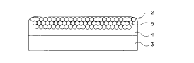
Fig. A1 shows a cross-sectional view of the first
transparent functional film of the present invention.
The transparent functional film has functional ultrafine
particle layers 2 formed in a region from the surface to
the interior of a hard coat layer 4 coated on a
transparent plastic film 3. As shown in Fig. A1, the
functional ultrafine particle layers 2 are mutually bound
by the binding action of the functional ultrafine
particles 5 per se, or the binding action of a binder
resin used in such an amount that the functional
ultrafine particles are not entirely embedded in the
binder resin. The uppermost layer of the functional
ultrafine particle layer 2 is embedded in the hard coat
layer 4 to such an extent that a thin film of the resin
for a hard coat layer is formed. It is noted that the
hard coat layer 4 having the functional ultrafine
particle layer 2, as such, is the first transparent
functional membrane of the present invention.
Fig. A2 is a cross-sectional view of the second
transparent functional film of the present invention.
The transparent functional film has functional ultrafine
particle layers 2 formed in a region from the interior to
13
2137207
the surface of a hard coat layer 4 coated on a
transparent plastic substrate film 3. As shown in Fig.
A2, the functional ultrafine particle layers 2 are
mutually bound by the binding action of the functional
ultrafine particles 5 per se, or the binding action of a
binder resin used in such an amount that the functional
ultrafine particles 5 are not entirely embedded in the
binder resin. The whole functional ultrafine particle
layer 2 is not embedded in the hard coat layer 4, and
part of the functional ultrafine particles 5 is exposed
on the surface;of the hard coat layer 4. Therefore, the
surface of the functional ultrafine particles has no thin
film of the resin for a hard coat layer and is in direct
contact with an air layer. The hard coat layer 4 having
a functional ultrafine particle layer 2, part of which is
exposed, as such, is the transparent functional membrane
of the present invention.
In the first and second transparent functional
membranes or transparent functional films according to
the present invention, the functional ultrafine particles
are localized in and fixed to the hard coat layer in a
region from the interface of the hard coat layer and an
air layer to the interior of the hard coat layer. This
constitution enables the properties of the functional
ultrafine particles to be easily developed without use of
the functional ultrafine particles in a large amount and,
at the same time, has the effect of providing a better
adhesion between the functional ultrafine particles and
the hard coat layer than the case where a layer
containing functional ultrafine particles is simply
formed on a hard coat layer.
Process for producina transparent functional film:
The first process for producing the first and second
transparent functional films according to the present
invention comprises the steps of: (1) forming a layer of
functional ultrafine particles on a release film; (2)
coating on a transparent plastic substrate film a resin
14
2137207
composition for a hard coat layer; (3) laminating, by
press-bonding, the coated transparent plastic substrate
film prepared in said step (2), as such, when said resin
composition for a hard coat layer contains no solvent, or
after removing a solvent when said resin composition for
a hard coat layer contains a solvent as a diluent, to the
coated release film prepared in said step (1) so that the
layer of functional ultrafine particles on the release
film faces the resin composition coating for a hard coat
layer on said transparent plastic substrate film, thereby
causing said layer of functional ultrafine particles to
be entirely or partly embedded in said resin composition
coating for a hard coat layer; and (4) full curing said
laminate prepared in said step (3) and peeling off said
release film to transfer said layer of functional
ultrafine particles to said transparent plastic substrate
film.
A modified embodiment of the first process for
producing the first and second transparent functional
films according to the present invention comprises the
steps of: (1) forming a layer of functional ultrafine
particles on a release film; (2) coating on a transparent
plastic substrate film a resin composition for a hard
coat layer; (3) laminating, by press-bonding, the coated
transparent plastic substrate film prepared in said step
(2), as such, when said resin composition for a hard coat
layer contains no solvent, or after removing a solvent
when said resin composition for a hard coat layer
contains a solvent as a diluent, to the coated release
film prepared in said step (1) so that the layer of
functional ultrafine particles on the release film faces
the resin composition coating for a hard coat layer on
said transparent plastic substrate film, thereby causing
said layer of functional ultrafine particles to be
entirely or partly embedded in said resin composition
coating for a hard coat layer; (4) half curing said
laminate prepared in said step (3) and peeling off said
2137207
release film to transfer said layer of functional
ultrafine particles to said transparent plastic substrate
film; (5) forming another functional membrane on said
half cured hard coat layer; and (6) full curing the
resultant assembly.
Fig. A3 is a flow diagram showing the above first
process for producing the first and second transparent
functional films of the present invention. Fig. A3 (a)
shows the step of coating a sol of functional ultrafine
particles 5 on a release film 1 to form a functional
ultrafine particle layer 2. Fig. A3 (b) shows the step
of press-bonding the above functional ultrafine particle
layer 2 formed on a release film 1 to a hard coat layer 4
provided on a transparent plastic substrate film 3. Fig.
A3 (c) shows the state of the functional ultrafine
particle layer which has been press-bonded to the hard
coat layer. Fig. A3 (d) shows the step of peeling off
the release film 1 after curing, in the press-bonded
state, a resin constituting the hard coat layer.
In the step (c), the resin constituting the hard
coat layer may be full cured (the first process).
Alternatively, it is possible to use a method wherein the
resin constituting the hard coat layer is half cured in
the step (c) and transferred to the step (d) of peeling
off the release film 1 and the resin constituting the
hard coat layer is full cured (a modified embodiment of
the first process). Curing of the hard coat layer in two
stages, i.e., half cure and full cure, offers the
advantage that, for example, when a layer is further
provided on the hard coat layer after half curing, the
adhesion between the hard coat layer and the layer
provided thereon can be increased.
The second process for producing the first and
second transparent functional films according to the
present invention comprises the steps of: (1) forming a
layer of functional ultrafine particles on a release
film; (2) coating on said layer of functional ultrafine
16
2137207
particles a resin composition for a hard coat layer to a
larger thickness than said layer of functional ultrafine
particles, thereby causing said layer of functional
ultrafine particles to be entirely or partly embedded in
said resin composition coating for a hard coat layer, and
full curing the coating to form a hard coat layer;
(3) laminating said release film with said hard coat
layer formed thereon to a transparent plastic substrate
film through an adhesive layer so that said hard coat
layer faces said transparent plastic substrate film; and
(4) peeling off said release film from the laminate
prepared in said step (3) to transfer said hard coat
layer to said transparent plastic substrate film.
A modified embodiment of the second process for
producing the first transparent functional films
according to the present invention comprises the steps
of: (1) forming a layer of functional ultrafine particles
on a release film; (2) coating on said layer of
functional ultrafine particles a resin composition for a
hard coat layer to a larger thickness than said layer of
functional ultrafine particles, thereby causing said
layer of functional ultrafine particles to be entirely or
partly embedded in said resin composition coating for a
hard coat layer, and half curing the coating to form a
hard coat layer; (3) laminating said release film with
said hard coat layer formed thereon to a transparent
plastic substrate film through an adhesive layer so that
said hard coat layer faces said transparent plastic
substrate film; (4) peeling off said release film from
the laminate prepared in said step (3) to transfer said
hard coat layer to said transparent plastic substrate
film; (5) forming another functional membrane on said
half cured hard coat layer; and (6) full curing said hard
coat layer.
Fig. A4 is a flow diagram showing the second process
for producing the first and second transparent functional
films according to the present invention. Fig. A4 (a)
17
2137207
shows the step of coating a sol of functional ultrafine
particles 5 on a release film 1 to form a functional
ultrafine particle layer 2 and coating thereon a resin
composition for a hard coat layer to a larger thickness
than the functional ultrafine particle layer 2, thereby
forming a hard coat layer 4. In the step (a), the hard
coat layer 4 may be full cured, or alternatively may be
half cured (a modified embodiment). Fig. A4 (b) shows
the step of laminating the hard coat layer 4 provided on
the release film 1 in the step (a) to a transparent
plastic substrate film 3 through an adhesive layer 6.
The adhesive layer 6 may be formed by coating on the hard
coat layer 4 or coating on the transparent plastic
substrate film 3. Fig. A4 (c) shows the state of the
hard coat layer 4 which has been press-bonded to the
transparent plastic substrate film 3. Fig. A4 (d) shows
the step of peeling off, in this press-bonded state, the
release film 1.
When the resin for a hard coat layer is half cured
in the step (a) of Fig. A4, the resin for a hard coat
layer can be full cured after peeling off the release
film 1 in the step (d). Curing of the hard coat layer in
two stages, i.e., half cure and full cure, offers the
advantage that, for example, when a layer is further
provided on the hard coat layer after half curing, the
adhesion between the hard coat layer and the layer
provided thereon can be increased.
The third process for producing the first and second
transparent functional film according to the present
invention comprises the steps of: (1) forming a layer of
functional ultrafine particles on a release film; (2)
coating on said layer of functional ultrafine particles a
resin composition for a hard coat layer to a larger
thickness than said layer of functional ultrafine
particles, thereby causing said layer of functional
ultrafine particles to be entirely or partly embedded in
said resin composition coating for a hard coat layer;
18
2137207
(3) laminating a transparent plastic substrate film to
said release film coated with said resin composition for
a hard coat layer so that said resin composition coating
for a hard coat layer faces said transparent plastic
substrate film, and full curing the resultant laminate to
form a hard coat layer; and (4) peeling off said release
film from the laminate prepared in said step (3) to
transfer said hard coat layer to said transparent plastic
substrate film.
A modified embodiment of the third process for
producing the first and second transparent functional
films according to the present invention comprises the
steps of: (1) forming a layer of functional ultrafine
particles on a release film; (2) coating on said layer of
functional ultrafine particles a resin composition for a
hard coat layer to a larger thickness than said layer of
functional ultrafine particles, thereby causing said
layer of functional ultrafine particles to be entirely or
partly embedded in said resin composition coating for a
hard coat layer; (3) laminating a transparent plastic
substrate film to said release film coated with said
resin composition for a hard coat layer so that said
resin composition coating for a hard coat layer faces
said transparent plastic substrate film, and half curing
the resultant laminate to form a hard coat layer; (4)
peeling off said release film from the half cured
laminate prepared in said step (3) to transfer said hard
coat layer to said transparent plastic substrate film;
(5) forming another functional membrane on the half cured
hard coat layer; and (6) full curing the hard coat layer.
Fig. A5 is a flow diagram showing the third process
for producing the first and second transparent functional
films according to the present invention. Fig. A5 (a)
shows the step of coating a sol of functional ultrafine
particles 5 on a release film 1 to form a functional
ultrafine particle layer 2 and coating thereon a resin
composition for a hard coat layer to a larger thickness
19
213?20~
than the functional ultrafine particle layer 2, thereby
forming a hard coat layer 4. In the step (a), the hard
coat layer 4 has not been yet subjected to a curing
treatment. Fig. A5 (b) shows the step of laminating the
uncured hard coat layer 4 formed on the release film 1
prepared in the above step (a) to a transparent plastic
substrate film 3. Fig. A5 (c) shows the state of the
uncured hard coat layer press-bonded to the transparent
substrate film. In the state shown in Fig. A5 (c), the
laminate is subjected to a curing treatment to full cure
or half cure the hard coat layer 4. Fig. A5 (d) shows
the step of peeling off the release film 1.
In the step (~), the resin composition for a hard
coat layer may be full cured. Alternatively, it is also
possible to a method wherein the resin composition for a
hard coat layer 4 is half cured in the step (c) and then
full cured after peeling off the release film 1 in the
step (d). Curing of the hard coat layer 4 in two stages,
i.e., half cure and full cure, offers the advantage that,
for example, when a layer is further provided on the hard
coat layer after half curing, the adhesion between the
hard coat layer 4 and the layer provided thereon can be
increased.
In the above processes for producing transparent
functional films, particularly in the production of a
transparent functional film wherein the functional
ultrafine particle layer is not entirely embedded in the
hard coat layer and part thereof is exposed on the
surface of the hard coat layer (the second transparent
functional film of the present invention), consideration
should be given to the viscosity of a resin for a hard
coat layer, the kind of the resin, the surface tension of
the resin, the particle diameter of functional ultrafine
particles, the filling ratio of the ultrafine particles,
the wettability of the functional ultrafine particles by
the resin for a hard coat layer, and the like.
2137207
More specifically, when a resin which has a high
viscosity or becomes dry to the touch (described below)
upon coating is selected as the resin for a hard coat
layer, part of the functional ultrafine particles is
likely to expose. Further, the selection of a resin
having a low surface tension or functional ultrafine
particles having a small particle diameter, which can
provide a high filling ratio, gives the same results.
Furthermore, the same results can be obtained when the
resin and the ultrafine particles are selected so that
the wettabilit~ of the ultrafine particles by the resin
is poor.
Fig. A6 is a flow diagram showing an embodiment of a
process for producing the second transparent functional
film according to the present invention. Fig. A6 (a)
shows the step of coating a sol of functional ultrafine
particles 5 on a release film 1 to form a functional
ultrafine particle layer 2. Fig. A6 (b) shows the step
of coating a resin composition for a hard coat layer on a
transparent plastic substrate film 3 and press-bonding
the resultant coating, which is dry to the touch, to the
above functional ultrafine particle layer 2 provided on
the release film 1. Fig. A6 (c) shows the state of the
coating for a hard coat layer, which has been press-
bonded to the above functional ultrafine particle layer
2. Since the release film 1 with the functional
ultrafine particle layer 2 being formed thereon is press-
bonded to the resin composition coating for a hard coat
layer in such a state that the resin composition coating
for a hard coat layer is dry to touch, the whole
functional ultrafine particle layer 2 provided on the
release film 1 is not entirely embedded in the hard coat
layer 4 with part of the functional ultrafine particle
layer 2 remaining outside the hard coat layer. Fig. A6
(d) shows the step of peeling off the release film 1
after irradiating a laminate in the press-bonded state
with an ionizing radiation, such as an electron beam or
21
2137207
ultraviolet light, to full cure the ionizing radiation
curing resin.
Release film:
A sheet, the surface of which has been subject to or
not been subjected to a treatment with a silicone,
fluorine, acryl-melamine, or the like for rendering the
surface of the sheet releasable, is generally used. The
surface of the sheet may be uneven. In this case, since
the unevenness is formed on the surface of the final
product, it is possible to impart an antireflection
effect or a glare protection effect to the transparent
functional film.
F»nctional ultrafin~ particles:
Examples of the functional ultrafine particles used
in the functional ultrafine particle layer include
ultrafine particles which have a size of not more than
200 nm and exhibit functions such as a UV screening
property, an electrical conductivity, an antistatic
property, and an antireflection property. For example,
ultrafine particles, such as Sn02 and ITO, are used for
the purpose of imparting electrical conductivity or
antistatic property to the transparent functional film,
while ultrafine particles having a low refractive index,
such as MgF2 and Si02, or ultrafine particles having a
high refractive index, such as Sb205, ZnO, ITO, Sn02, and
Ti02, are used for the purpose of imparting an
antireflection property.
The antireflection film using the ultrafine
particles having a high refractive index can be prepared
by forming, on a coating containing ultrafine particles
having a high refractive index, a thin film having a
single layer or multilayer structure using an inorganic
material having a low refractive index, such as MgF2 or
Si02, or a metallic material by vapor deposition,
sputtering, plasma CVD or the like, or alternatively
forming, on a coating containing ultrafine particles
having a high refractive index, a coating layer having a
22
2137207
single layer or multilayer structure using a resin
composition, having a low refractive index, containing an
inorganic material having a low refractive index, such as
MgF2 or Si02, a metallic material, or the like.
On the other hand, ultrafine particles, such as
Sb205, ZnO, and Ti02, are used for the purpose of
imparting the UV screening property.
In the present invention, the term "ultrafine
particles" means particles having an average particle
diameter of not more than 200 nm, preferably not more
than 100 nm, still preferably in the range of from 5 to
70 nm. This definition is true of the inventions
belonging to group B and group C which will be described
later.
These functional ultrafine particles may be those
which have been subjected to a treatment with a coupling
agent for rendering the surface thereof hydrophobic. The
treatment for rendering the surface hydrophobic
introduces a hydrophobic group onto the surface of the
functional ultrafine particles, so that the affinity of
the ultrafine particles for the ionizing radiation curing
resin is increased, enhancing the bond between the
ultrafine particles and the ionizing radiation curing
resin. Examples of the coupling agent include a silane
coupling agent, a titanate coupling agent, and an alumina
coupling agent. The amount of the coupling agent added
is 0 (zero) exclusive to 30 parts by weight, preferably 0
exclusive to 10 parts by weight.
When the functional ultrafine particles is those
having an inert surface, such as MgF2, it is possible to
use a method which comprises previously adding a sol of
Si02 to coat Si02 on the surface of the functional
uitrafine particles and treating the coated functional
ultrafine particles with a coupling agent. The above
coating treatment with Si02 enables a large amount of a
hydrophilic group to be introduced onto the surface of
the functional ultrafine particles, which in turn enables
23
2137207
the subsequent treatment with a coupling agent thereby to
ensurely introduce a larger amount of a hydrophobic
group, so that the affinity of the functional ultrafine
particles for the resin is further increased to enhance
the bond strength between the functional ultrafine
particles and the resin.
Method for formina functional ultrafine particle layer on
release film:
A functional ultrafine particle layer is formed on a
release film by coating on a release film a sol of
functional ultrafine particles, as such, or a sol of
functional ultrafine particles containing a binder resin.
The functional' ultrafine particle layer can be
successfully formed on the release film by the binding
action of the functional ultrafine particles per se
without using any binder resin. If the binding action is
weak, the binder resin may be, if necessary, used. The
amount of the binder resin is preferably such that the
functional ultrafine particles are not entirely embedded
in the binder resin, because the functional ultrafine
particles are mutually bound with the surface of the
functional ultrafine particles being exposed. This is
favorable to develop the function of the functional
ultrafine particles, particularly when the functional
ultrafine particle layer is used as an antireflection
film.
The above binder resin may be the conventional
binder resins, such as a thermosetting resin, a
thermoplastic resin, and an ionizing radiation curing
resin. However, when the adhesion to the underlayer (an
ionizing radiation curing resin layer) is taken into
consideration, the use of an ionizing radiation curing
resin is preferred. In this case, the ionizing radiation
curing resin is preferably of a solvent semicuring resin.
A colorant may be added to the binder resin.
Transparent plastic substrate film:
24
213'~2U7
Any transparent plastic film may be suitably used as
the transparent plastic substrate film for the
transparent functional film, and example thereof include
a triacetyl cellulose film, a diacetyl cellulose film, a
cellulose acetate butyrate film, a polyether sulfone
film, a polyacrylic resin film, a polyurethane resin
film, a polyester film, a polycarbonate film, a
polysulfone film, a polyether film, a trimethylpentane
film, a polyether ketone film, and a (meth)acrylonitrile
film. Among them, a triacetyl cellulose film and a
uniaxial stretched polyester film are particularly
favorable because they have excellent transparency and no
optical anisotropy. The thickness of the transparent
substrate film is, in general, preferably in the range of
from about 8 to 1000 ~.un.
Hard coat Dyer:
The binder resin used in the hard coat layer may be
any resin (for example, a thermoplastic resin, a
thermosetting resin, and an ionizing radiation curing
resin) so far as it is transparent. In order to impart a
hard property, the thickness of the hard coat layer is
not less than 0.5 dim, preferably not less than 3 Win.
When the thickness falls within the above range, it is
possible to maintain the hardness, so that the hard
property can be imparted to the antireflection film.
In the present invention, "having a hard property"
or "hard coat" refers to a coating having a hardness of
not less than H as measured by a pencil hardness test
specified in JIS K5400.
In order to further improve the hardness of the hard
coat layer, it is preferred to use, as the binder resin
for.the hard coat layer, a reaction curing resin, i.e., a
thermosetting resin and/or an ionizing radiation curing
resin. Examples of the thermosetting resin include a
phenolic resin, a urea resin, a diallyl phthalate resin,
a melamine resin, a guanamine resin, an unsaturated
polyester resin, a polyurethane resin, an epoxy resin,. an
2137207
aminoalkyd resin, a melamine-urea copolycondensed resin,
a silicon resin, and a polysiloxane resin. If necessary,
curing agents, such as crosslinking agents and
polymerization initiators, polymerization accelerators,
solvents, viscosity modifiers, and the like may be added
to these resins.
The ionizing radiation curing resin is preferably
one having an acrylate functional group, and examples
thereof include a polyester resin, a polyether resin, an
acrylic resin, an epoxy resin, a urethane resin, an alkyd
resin, a spiroacetal resin, a polybutadiene resin,. and a
polythiol-polyene resin having a relatively low molecular
weight, an oligomer'or a prepolymer of a (meth)acrylate
or the like of a polyfunctional compound, such as a
polyhydric alcohol, and those containing a relatively
large amount of a reactive diluent, such as a
monofunctional monomer, such as ethyl (meth)acrylate,
ethylhexyl (meth)acrylate, styrene, methylstyrene, or N-
vinylpyrrolidone, and a polyfunctional monomer, for
example, trimethylolpropane tri(meth)acrylate, hexanediol
(meth)acrylate, tripropylene glycol di(meth)acrylate,
diethylene glycol di(meth)acrylate, pentaerythritol
tri(meth)acrylate, dipentaerythritol hexa(meth)acrylate,
1,6-hexanediol di(meth)acrylate, or neopentyl glycol
di(meth)acrylate.
Among them, a mixture of a polyester acrylate with
polyurethane acrylate is particularly preferred. The
reason for this is as follows. The polyester acrylate
provides a coating having a very high hardness and is,
therefore, suitable for the formation of a hard coat.
Since, however, a coating consisting of polyester
acrylate alone has low impact resistance and is fragile,
the polyurethane acrylate is used in combination with the
polyester acrylate to impart the impact resistance and
flexibility to the coating. The proportion of the
polyurethane acrylate incorporated based on 100 parts by
weight of the polyester acrylate is not more than 30
26
2137207
parts by weight. This is because the incorporation of
the polyurethane acrylate in an amount exceeding the
above upper limit 30 parts by weight makes the coating so
flexible that the hard property is lost.
In order to bring the above ionizing radiation
curing resin composition to W curing type, it is
preferred to incorporate, into the ionizing radiation
curing resin composition, a photopolymerization
initiator, such as an acetophenone compound, a
benzophenone compound, Michler's benzoylbenzoate, an a-
amyloxime ester, tetramethyl thiuram monosulfide, or a
thioxanthone compound, and a photosensitizer, such as n-
butylamine, triethylamine, or tri-n-butylphosphine. In
the present invention, it is particularly preferred to
incorporate urethane acrylate or the like as an oligomer
and dipentaerythritol hexa(meth)acrylate or the like as a
monomer.
In order to impart particularly flexibility to the
hard coat layer, a solvent type resin may be incorporated
in an amount of 10 to 100 parts by weight based on 100
parts by weight of the ionizing radiation curing resin.
A thermoplastic resin is mainly used as the solvent type
resin. The solvent type thermoplastic resin added to the
ionizing radiation curing resin may be any conventional
resin used in the art. In particular, when a blend of a
polyester acrylate with a polyurethane acrylate is used
as the ionizing radiation curing resin, the use of
polymethyl methacrylate acrylate or polybutyl
methacrylate acrylate as the solvent type resin enables
the hardness of the coating to be kept high. Further,
this is advantageous also from the viewpoint of
transparency, particularly, low haze value, high
transmittance, and compatibility, because since the
refractive index of the polymethyl methacrylate acrylate
or polybutyl methacrylate acrylate is close to that of
the main ionizing radiation curing resin, the
transparency of the coating is not lost.
27
213720?
Further, particularly when a cellulosic resin, such
as triacetyl cellulose, is used as the transparent
plastic substrate film, the use of a cellulosic resin,
such as nitrocellulose, acetyl cellulose, cellulose
acetate propionate, or ethylhydroxyethyl cellulose, is
advantageous from the viewpoint of the adhesion and
transparency of the coating.
The reason for this is as follows. If toluene is
used as a solvent for the above cellulosic resin, despite
the fact that toluene does not dissolve triacetyl
cellulose as the transparent plastic substrate film, when
a coating solution containing this solvent type resin is
coated on the transparent plastic substrate film, the
adhesion between the transparent plastic substrate film
and the coating resin can be improved. Further, in this
case, since toluene does not dissolve triacetyl cellulose
as the transparent plastic substrate film, the surface of
the transparent plastic substrate film is not whitened,
enabling the transparency to be maintained.
In the hard coat layer, when an ionizing radiation
curing resin is used as the binder resin, the ionizing
radiation curing resin may be cured by the conventional
curing method usually employed for curing ionizing
radiation curing resins, that is, applying an electron
beam or ultraviolet light. For example, in the case of
curing with an electron beam, use may be made of an
electron beam or the like having an energy of 50 to 1000
KeV, preferably 100 to 300 Kev, emitted from various
electron beam accelerators, such as a Cockcroft-Walton
(type) accelerator, a van de Graaff accelerator, a
resonance transformer accelerator, an insulation core
transformer accelerator, a linear accelerator, a dynatron
accelerator, and a high frequency accelerator. On the
other hand, in the case of curing with UV, use may be
made of ultraviolet light emitted from an ultrahigh
pressure mercury lamp, a high pressure mercury lamp, a
28
2137207
low pressure mercury lamp, a carbon arc, a xenon arc, a
metal halide lamp, and the like.
Half cure:
In the process for producing a transparent
functional film according to the present invention, the
half cure include a. ionizing radiation curing resin
semicrosslinking type half cure, b. ionizing radiation
curing resin/thermosetting resin (or thermoplastic resin)
blend type half cure, and c. solvent type/half cure type
combined half cure.
a Ionizing radiation curing resin semicrosslinkina
twe half cure
The ionizing radiation curing resin semicrosslinking
type half cure refers to a half cured state created by
coating the conventional ionizing radiation curing resin
and irradiating the coating with an ionizing radiation,
such as W or an electron beam, under regulated
irradiation conditions to cause semicrosslinking.
b Ionizing radiation curing resin/thermosettina
resin (or thermoplastic resin) blend type half
cure
The ionizing radiation curing resin/thermosetting
resin (or thermoplastic resin) blend type half cure
refers to a half cured state created by coating a resin
composition comprising a mixture of an ionizing radiation
curing resin with a thermosetting resin or a
thermoplastic resin and, when the thermosetting resin is
used, applying heat to the coating.
Solvent t~~e/half cure tvoe combined half cure
The solvent type/half cure type combined half cure
refers to a half cured state created by coating the
conventional ionizing radiation curing resin with a
solvent being added thereto, removing the solvent to form
a coating, and irradiating the dried coating with an
ionizing radiation. This half cured state is the same as
the semi-cured state described in Japanese Patent Laid-
Open No. 20249/1989.
29
213207
Drv-to-touch state:
In the production of the second transparent
functional film of the present invention, it is necessary
to expose part of the functional ultrafine particle layer
on the hard coat layer. When the coating of the resin
composition for a hard coat layer is dry to the touch, it
has a high viscosity. In this state, when a functional
ultrafine particle layer is brought into contact with the
coating, the whole functional ultrafine particle layer is
not entirely embedded in the hard coat layer with part of
the functionalFultrafine particle layer being exposed.
That the hard coat layer is brought to the dry-to-touch
state offers the advantage that the adhesion between the
hard coat layer and the functional ultrafine particle
layer can be improved.
The coating of the resin composition for a hard coat
layer can be made dry to the touch by a a method wherein
an ionizing radiation curing resin, which is dry to the
touch, is used, b a method wherein a resin having a
pressure-sensitive adhesive property is incorporated in
the ionizing radiation curing resin.
In the method a wherein an ionizing radiation curing
resin, which is dry to the touch, is used, for example,
ionizing radiation curing resins as described in the
following (i) and (ii), which are dry to the touch, may
be used.
(i) Resin comprising a polymer having a glass
transition temperature of 0 to 250°C with a
radical polymerizable unsaturated group being
introduced therein
Specifically, mention may be made of resins prepared
by polymerizing or copolymerizing the following monomers
and introducing a radical copolymerizable unsaturated
group into the polymers or copolymers by the methods a)
to d) which will be described later.
Monomers having a hydroxyl group: for example, N-
methylol (meth)acrylamide, 2-hydroxyethyl (meth)acrylate,
2137207
2-hydroxypropyl (meth)acrylate, 2-hydroxybutyl
(meth)acrylate, and 2-hydroxypropyl (meth)acrylate.
Monomers having a carboxyl group: for example,
(meth)acrylic acid and (meth)acryloyloxyethyl
monosuccinate.
Monomers having an epoxy group: for example,
glycidyl (meth)acrylate.
Monomers having an aziridinyl group: for example, 2-
aziridinyl ethyl (meth)acrylate and 2-aziridinyl allyl
propionate.
Monomers having an amino group: for example,
(meth)acrylamide, diacetone (meth)acrylamide,
dimethylaminoethyl (meth)acrylate, and diethylaminoethyl
(meth)acrylate.
Monomers having a sulfone group: for example, 2-
(meth)acrylamido-2-methylpropanesulfonic acid.
Monomers having an isocyanate group: for example, an
adduct of a diisocyanate with a radical copolymer having
an active hydrogen, such as an adduct of 2,4-toluene
diisocyanate with 2-hydroxyethyl (meth)acrylate (mole
ratio = 1 . 1).
Further, in order to adjust the glass transition
temperature of the copolymer or adjust the properties of
the cured membrane, it is possible to copolymerize the
above monomer with the following copolymerizable
compound. Examples of the copolymerizable monomer
include methyl (meth)acrylate, propyl (meth)acrylate,
butyl (meth)acrylate, isobutyl (meth)acrylate, t-butyl
(meth)acrylate, isoamyl (meth)acrylate, cyclohexyl
(meth)acrylate, and 2-ethylhexyl (meth)acrylate.
Ionizing radiation curing resins, such as W curing
resins or electron beam curing resins, can be prepared by
introducing a radical polymerizable unsaturated group
into homopolymers or copolymers of the above monomers by
the following methods a) to d).
a) When the homopolymer or copolymer is a
homopolymer or a copolymer of a monomer having a hydroxyl
31
213720?
group, it is condensed with a monomer having a carboxyl
group, such as methacrylic acid, or the like.
b) When the homopolymer or copolymer is a
homopolymer or a copolymer of a monomer having a carboxyl
group or a sulfonate group, it is condensed with the
above monomer having a hydroxyl group.
c) When the homopolymer or copolymer is a
homopolymer or a copolymer of a monomer having an epoxy
group, an isocyanate group, or an aziridinyl group, it is
subjected to an addition reaction with the above monomer
having a hydroxyl group or a carboxyl group.
d) When the homopolymer or copolymer is a
homopolymer or a copolymer of a monomer having a hydroxyl
group or a carboxyl group, it is subjected to an addition
reaction with a monomer having an epoxy group, a monomer
having an aziridinyl group or a 1 . 1 adduct of a
diisocyanate compound and an acrylic ester monomer having
a hydroxyl group.
(ii) Resin, having a radical polymerizable
unsaturated group, which has a melting point
in the range of from room temperature (20°C)
to 250°C
In the above reactions, it is preferred to add a
very small amount of a polymerization inhibitor, such as
hydroquinone, to the reaction systems, and the reactions
are carried out while feeding dried air to the reaction
systems.
Specific example thereof include stearyl acrylate,
stearyl (meth)acrylate, triacryl isocyanate,
cyclohexanediol (meth)acrylate, spiroglycol diacrylate,
and spiroglycol (meth)acrylate.
The resin having an adhesive property used in the
above method b wherein a resin having an adhesive
property is incorporated in an ionizing radiation curing
resin is a resin which can impart an adhesive property to
the ionizing radiation curing resin. Such a resin
generally comprises a mixture of a pressure sensitive
32
2137207
adhesive with an ionizing radiation curing resin. When
the ionizing radiation curing resin is in an
uncrosslinked state and not liquid and has an adhesive
property, it, as such, may be used. In particular, in
order to keep the hardness of the coating high,
thermoplastic resins, such as polymethyl methacrylate and
polybutyl methacrylate, are suitable for imparting an
adhesive property to the ionizing radiation curing resin.
Other resins suitable for imparting the adhesive
property to the ionizing radiation curing resin include
the conventional resins used for pressure-sensitive
adhesive tapes and pressure-sensitive adhesive seals, and
examples thereof include rubber resins, such as
polyisoprene rubber, polyisobutylene rubber, styrene-
butadiene rubber, and butadiene-acrylonitrile rubber, a
(meth)acrylic ester resin, a polyvinyl ether resin, a
polyvinyl acetate resin, a polyvinyl chloride/vinyl
acetate copolymer resin, a polystyrene resin, a polyamide
resin, a polychlorinated olefin resin, and a polyvinyl
butyral resin. They contain proper tackifiers, such as a
rosin, a dammar, a polymerized rosin, a partially
hydrogenated rosin, an ester rosin, a polyterpene resin,
a modified terpene, a petroleum resin, a cyclopentadiene
resin, a phenolic resin, and a coumarone-indene resin,
and, if necessary, a softener, a filler, an antioxidant,
and the like.
The proportion of the resin having an adhesive
property incorporated in the ionizing radiation curing
resin is preferably not more than 50 parts by weight
based on 100 parts by weight of the ionizing radiation
curing resin, from the viewpoint of forming a dry-to-
touch coating.
Antireflection film and brocess for oroducina the same:
The antireflection film of the present invention can
be classified into four types, two types of which are
such that ultrafine particles having a low refractive
index are used as the functional ultrafine particles and
33
2137207
the other two types are such that ultrafine particles
having a high refractive index are used as the functional
ultrafine particles.
The first antireflection film of the present
invention comprises: a hard coat layer with ultrafine
particles having a low refractive index being localized
in and fixed to said hard coat layer in a region from the
interface of the hard coat layer and an air layer to the
interior of the hard coat layer; and a transparent
plastic substrate film having said hard coat layer fixed
thereon, said hard coat layer having a higher refractive
index than said ultrafine particles having a low
refractive index. 'This antireflection film is the same
as the transparent functional film shown in Fig. 1,
except that the functional ultrafine particles are
ultrafine particles having a low refractive index.
The second antireflection film of the present
invention comprises: a hard coat layer with ultrafine
particles having a low refractive index being localized
in and fixed to said hard coat layer in a region from the
interface of the hard coat layer and an air layer to the
interior of the hard coat layer, part of said ultrafine
particles having a low refractive index being exposed on
the surface of said hard coat layer; and a transparent
plastic substrate film having said hard coat layer fixed
thereon, said hard coat layer having a higher refractive
index than said ultrafine particles having a low
refractive index. This antireflection film is the same
as the transparent functional film shown in Fig. A2,
except that the functional ultrafine particles are
ultrafine particles having a low refractive index.
The third antireflection film of the present
invention comprises: a hard coat layer with ultrafine
particles having a high refractive index being localized
in and fixed to said hard coat layer in a region from the
surface of said hard coat layer to the interior of said
hard coat layer; a transparent plastic substrate film
34
2137207
with said hard coat layer being fixed to the reverse
surface thereof; and a layer, having a low refractive
index, formed on the surface of said hard coat layer with
said ultrafine particles having a high refractive index
being localized therein, said hard coat layer having a
lower refractive index than said ultrafine particles
having a high refractive index. This antireflection film
corresponds to a transparent functional film shown in
Fig. A9, wherein the functional ultrafine particles are
ultrafine particles having a high refractive index.
The fourth antireflection film of the present
invention comprises: a hard coat layer with ultrafine
particles having a high refractive index being localized
in and fixed to said hard coat layer in a region from the
surface of said hard coat layer to the interior of said
hard coat layer, part of said ultrafine particles having
a high refractive index being exposed on the surface of
said hard coat layer; a transparent plastic substrate
film with said hard coat layer being fixed thereon; and a
layer, having a low refractive index, formed on the
surface of said hard coat layer with said ultrafine
particles having a high refractive index being localized
therein and part of said ultrafine particles having a
high refractive index being exposed thereon, said hard
coat layer having a lower refractive index than said
ultrafine particles having a high refractive index. This
antireflection film corresponds to a transparent
functional film shown in Fig. A12, wherein the functional
ultrafine particles are ultrafine particles having a high
refractive index.
The process for producing the first antireflection
film of the present invention is characterized in that,
in the above first process for producing the first
transparent functional film, ultrafine particles having a
low refractive index are used as the functional ultrafine
particles and a resin composition for a hard coat layer,
having a higher refractive index than the ultrafine
213720
particles having a low refractive index, is used as the
resin composition for a hard coat layer.
The process for producing the second antireflection
film of the present invention is characterized in that,
in the above process for producing the second transparent
functional film, ultrafine particles having a low
refractive index are used as the functional ultrafine
particles and a resin composition for a hard coat layer,
having a higher refractive index than the ultrafine
particles having a low refractive index, is used as the
resin composition for a hard coat layer.
The first process for producing the third
antireflection film of the present invention comprises
the steps of: (1) forming on a release film a layer of
ultrafine particles having a high refractive index; (2)
coating on a transparent plastic substrate film a resin
composition for a hard coat layer, having a lower
refractive index than said layer of ultrafine particles
having a high refractive index; (3) laminating, by press-
bonding, the coated transparent plastic substrate film
prepared in said step (2), as such, when said resin
composition for a hard coat layer contains no solvent, or
after removing a solvent when said resin composition for
a hard coat layer contains a solvent as a diluent, to the
coated release film prepared in said step (1) so that the
layer of ultrafine particles having a high refractive
index on the release film faces the resin composition
coating for a hard coat layer on said transparent plastic
substrate film, thereby causing said layer of ultrafine
particles having a high refractive index to be entirely
or partly embedded in said resin composition coating for
a hard coat layer; (4) full curing said laminate prepared
in said step (3) to form a hard coat layer and peeling
off said release film to transfer said layer of ultrafine
particles having a high refractive index to said
transparent plastic substrate film; and (5) forming a
36
2137207
layer having a low refractive index on said hard coat
layer.
A modified embodiment of the first process for
producing the third antireflection film according to the
present invention comprises the steps of: (1) forming on
a release film a layer of ultrafine particles having a
high refractive index; (2) coating on a transparent
plastic substrate film a resin composition for a hard
coat layer, having a lower refractive index than said
layer of ultrafine particles having a high refractive
index; (3) laminating, by press-bonding, the coated
transparent plastic substrate film prepared in said step
(2), as such, when said resin composition for a hard coat
layer contains no solvent, or after removing a solvent
when said resin composition for a hard coat layer
contains a solvent as a diluent, to the coated release
film prepared in said step (1) so that the layer of
ultrafine particles having a high refractive index on the
release film faces the resin composition coating for a
hard coat layer on said transparent plastic substrate
film, thereby causing said layer of ultrafine particles
having a high refractive index to be entirely or partly
embedded in said resin composition coating for a hard
coat layer; (4) half curing said laminate prepared in
said step (3) to form a hard coat layer and peeling off
said release film to transfer said layer of ultrafine
particles having a high refractive index to said
transparent plastic substrate film; (5) forming a layer
having a low refractive index on the half cured hard coat
layer; and (6) full cure said hard coat layer.
The second process for producing the third
antireflection film according to the present invention
comprises the steps of: (1) forming on a release film a
layer of ultrafine particles having a high refractive
index; (2) coating on said layer of ultrafine particles
having a high refractive index a resin composition for a
hard coat layer, having a lower refractive index than
37
2137207
said layer of ultrafine particles having a high
refractive index, to a larger thickness than said layer
of ultrafine particles having a high refractive index,
thereby causing said layer of ultrafine particles having
a high refractive index to be entirely or partly embedded
in said resin composition coating for a hard coat layer,
and full curing the coating to form a hard coat layer;
(3) laminating said release film with said hard coat
layer formed thereon to a transparent plastic substrate
film through an adhesive layer so that said hard coat
layer faces said transparent plastic substrate film; (4)
peeling off said release film from the laminate prepared
in said step (3) to'transfer said hard coat layer to said
transparent plastic substrate film; and (5) forming a
layer having a low refractive index on said hard coat
layer.
A modified embodiment of the second process for
producing the third antireflection film according to the
present invention comprises the steps of: (1) forming on
a release film a layer of ultrafine particles having a
high refractive index; (2) coating on said layer of
ultrafine particles having a high refractive index a
resin composition for a hard coat layer, having a lower
refractive index than said layer of ultrafine particles
having a high refractive index, to a larger thickness
than said layer of ultrafine particles having a high
refractive index, thereby causing said layer of ultrafine
particles having a high refractive index to be entirely
or partly embedded in said resin composition coating for
a hard coat layer, and half curing the coating to form a
hard coat layer; (3) laminating said release film with
said hard coat layer formed thereon to a transparent
plastic substrate film through an adhesive layer so that
said hard coat layer faces said transparent plastic
substrate film; (4) peeling off said release film from
the laminate prepared in said step (3) to transfer said
hard coat layer to said transparent plastic substrate
38
2137207
film; (5) forming a layer having a low refractive index
on the half cured hard coat layer; and (6) full curing
said hard coat layer.
The third process for producing the third
antireflection film according to the present invention
comprises the steps of: (1) forming on a release film a
layer of ultrafine particles having a high refractive
index; (2) coating on said layer of ultrafine particles
having a high refractive index a resin composition for a
hard coat layer, having a lower refractive index than
said layer of ultrafine particles having a high
refractive index, to a larger thickness than said layer
of ultrafine particles having a high refractive index,
thereby causing said layer of ultrafine particles having
a high refractive index to be entirely or partly embedded
in said resin composition coating for a hard coat layer;
(3) laminating a transparent plastic substrate film to
said release film coated with said resin composition for
a hard coat layer so that said resin composition coating
for a hard coat layer faces said transparent plastic
substrate film, and full curing the resultant laminate to
form a hard coat layer; (4) peeling off said release
film from the laminate prepared in said step (3) to
transfer said hard coat layer to said transparent plastic
substrate film; and (5) forming a layer having a low
refractive index on the cured hard coat layer.
A modified embodiment of the third process for
producing the third antireflection film according to the
present invention comprises the steps of: (1) forming on
a release film a layer of ultrafine particles having a
high refractive index; (2) coating on said layer of
ultrafine particles having a high refractive index a
resin composition for a hard coat layer, having a lower
refractive index than said layer of ultrafine particles
having a high refractive index, to a larger thickness
than said layer of ultrafine particles having a high
refractive index, thereby causing said layer of ultrafine
39
2137207
particles having a high refractive index to be entirely
or partly embedded in said resin composition coating for
a hard coat layer; (3) laminating a transparent plastic
substrate film to said release film coated with said
resin composition for a hard coat layer so that said
resin composition coating for a hard coat layer faces
said transparent plastic substrate film, and half curing
the resultant laminate to form a hard coat layer; (4)
peeling off said release film from the half cured
laminate prepared in said step (3) to transfer said hard
coat layer to said transparent plastic substrate film;
(5) forming a layer having a low refractive index on the
half cured hard coat layer; and (6) full curing said hard
coat layer.
In the above processes for producing antireflection
films, particularly an antireflection film, wherein
ultrafine particles having a high refractive index are
not entirely embedded in the hard coat layer with part of
the ultrafine particles having a high refractive index
being exposed on the surface of the hard coat layer (the
fourth antireflection film of the present invention), can
be produced by increasing the viscosity of the resin for
a hard coat layer, properly selecting the kind of the
resin, properly selecting a resin having a high surface
tension as the above type of resin, and taking into
consideration the particle diameter of the ultrafine
particles having a high refractive index, the filling
ratio of the ultrafine particles, the wettability of the
ultrafine particles having a high refractive index by the
resin for a hard coat layer, and the like.
An embodiment of a process for producing the fourth
antireflection film according to the present invention
comprises the steps of: (1) forming on a release film a
layer of ultrafine particles having a high refractive
index; (2) coating on a transparent plastic substrate
film a resin composition for a hard coat layer, having a
lower refractive index than said layer of ultrafine
2137207
particles having a high refractive index; (3) laminating,
by press-bonding, the coated transparent plastic
substrate film prepared in said step (2) to the coated
release film prepared in said step (1), when the coating
of the resin composition for a hard coat layer is dry to
the touch, so that the layer of ultrafine particles
having a high refractive index on the release film faces
the coating on said transparent plastic substrate film,
thereby causing said layer of ultrafine particles having
a high refractive index to be partly embedded in said
resin composition coating for a hard coat layer; (4) full
curing said laminate prepared in said step (3) to form a
hard coat layer and peeling off said release film to
transfer said layer of ultrafine particles having a high
refractive index to said transparent plastic substrate
film; and (5) forming a layer having a low refractive
index on said layer of ultrafine particles, having a high
refractive index, part of which is exposed on said hard
coat layer.
Another embodiment of a process for producing the
forth antireflection film according to the present
invention comprises the steps of: (1) forming on a
release film a layer of ultrafine particles having a high
refractive index; (2) coating on a transparent plastic
substrate film a resin composition for a hard coat layer,
having a lower refractive index than said layer of
ultrafine particles having a high refractive index; (3)
laminating, by press-bonding, the coated transparent
plastic substrate film prepared in said step (2) to the
coated release film prepared in said step (1), when the
coating of the resin composition for a hard coat layer is
dry to the touch, so that the layer of ultrafine
particles having a high refractive index on the release
film faces the coating on the transparent plastic
substrate film, thereby causing said layer of ultrafine
particles having a high refractive index to be partly
embedded in said resin composition coating for a hard
41
2137207
coat layer; (4) half curing said laminate prepared in
said step (3) to form a hard coat layer and peeling off
said release film to transfer said layer of ultrafine
particles having a high refractive index to said
transparent plastic substrate film; (5) forming a layer
having a low refractive index on said layer of ultrafine
particles, having a high refractive index, part of which
is exposed on said hard coat layer; and (6) full curing
said hard coat layer.
In the processes for producing antireflection films
according to the present invention, when a layer having a
low refractive index is formed on the hard coat layer by
coating or a vapor'growth process, the formation of the
layer having a low refractive index on the half cured
hard coat layer followed by full curing offers the
advantage that the adhesion of the layer having a low
refractive index can be improved. The half cure is the
same as described~above in connection with the
transparent functional film.
Ultrafine particle layer havina hiah refractive index in
antireflection film:
Examples of the ultrafine particles having a high
refractive index used in the ultrafine particle layer
having a high refractive index in the antireflection film
of the present invention include zn0 (refractive index:
1.90), Ti02 (refractive index: 2.3-2.7), Ce02 (refractive
index: 1.95), Sb205 (refractive index: 1.71), Sn02, ITO
(refractive index: 1.95), Y203 (refractive index: 1.87),
La203 (refractive index: 1.95), Zr02 (refractive index:
2.05), and A1203 (refractive index: 1.63). Among the
above ultrafine particles having a high refractive index,
ZnO, Ti02, Ce02, and the like are preferred because UV
screening properties can be further imparted to the
antireflection film of the present invention. Further,
the use of an antimony-doped Sn02 or ITO is preferred
from the viewpoint of improving electronic conductivity
to prevent the adherence of dust by virtue of an
42
2137207
antistatic effect, or to attain an electromagnetic wave
shielding effect when the antireflection film of the
present invention is used in CRT. In order to make the
hard coat layer transparent, the particle diameter of the
ultrafine particle having a high refractive index is
preferably not more than 400 nm.
Ultrafine particle layer having low refractive index in
antireflection film:
Examples of the ultrafine particles having a low
refractive index used in the ultrafine particle layer
having a low refractive index in the antireflection film
of the present invention include inorganic materials,
such as LiF (refractive index: 1.4), MgF2 (refractive
index: 1.4), 3NaF-A1F3 (refractive index: 1.4), A1F3
(refractive index: 1.4), Na3A1F6 (cryolite, refractive
index: 1.33), and SiOx (x: 1.50<_x<_2.00)(refractive index:
1.35-1.48).
Layer having low refractive index in antireflection film-
In the antireflection film of the present invention,
a layer having a low refractive index is further provided
on the surface of the hard coat layer with ultrafine
particles having a high refractive index being localized
therein. The refractive index of the layer having a low
refractive index is lower than those of the hard coat
layer and the ultrafine particle layer having a high
refractive index. The refractive index nL of the layer
having a low refractive index is, of course, lower than
the refractive index nH of the hard coat layer. Further,
when the relationship between the refractive index nL of
the layer having a low refractive index and the
refractive index nH of the hard coat layer is closer to a
requirement represented by the following formula, the
antireflection effect attained is better. Therefore, it
is preferred to provide the layer having a low refractive
index and the hard coat layer so that the relationship
between the refractive index nL of the layer having a low
refractive index and the refractive index nH of the hard
43
2137207
coat layer is as closer to a requirement represented by
the following formula as possible.
nL =
The layer having a low refractive index may be
formed using any material having a low refractive index
so far as the above requirement is met. The material may
be any of inorganic materials and organic materials.
Examples of the inorganic material having a low
refractive index include LiF (refractive index: 1.4),
MgF2 (refractive index: 1.4), 3NaF-A1F3 (refractive
index: 1.4), AlF3 (refractive index: 1.4), Na3AlF6
(cryolite, refractive index: 1.33), and SiOx (x:
1.50~2.00)(refractive index: 1.35-1.48).
It is preferred to form the layer having a low
refractive index using an inorganic material having a low
refractive index because the formed layer has a high
hardness. In particular, when a layer of SiOX (wherein x
is 1.504.00, preferably 1.70<_x<_2.20) is formed by the
plasma CVD process, it has a good hardness and an
excellent adhesion to the hard coat layer and, further,
heat damage to the transparent plastic substrate film can
be reduced as compared with the case where other vapor
growth processes are used.
The organic material having a low refractive index
is preferably an organic material, such as a polymer with
a fluorine atom being introduced thereinto, because the
refractive index is low and not more than 1.45.
Polyvinylidene fluoride (refractive index n = 1.40) can
be mentioned as a resin usable with a solvent because it
is easy to handle. When polyvinylidene fluoride is used
as the organic material having a low refractive index,
the refractive index of the layer having a low refractive
index becomes about 1.40. It is also possible to add an
acrylate having a low refractive index, such as
trifluoroethyl acrylate (refractive index n = 1.32), in
an amount of 10 to 300 parts by weight, preferably 100 to
200 parts by weight, for the purpose of further lowering
44
213720
the refractive index of the layer having a low refractive
index.
It is noted that the trifluoroethyl acrylate is of
monofunctional type and, therefore, the strength of the
layer having a low refractive index is not satisfactory.
For this reason, it is preferred to further add a
polyfunctional acrylate, for example, dipentaerythritol
hexacrylate (abbreviation: DPHA, tetrafunctional typey,
which is an ionizing radiation curing resin. The larger
the amount of DPHA added, the higher the strength of the
layer. However, the lower the amount of DPHA added, the
lower the refractive index. For this reason, it is
recommended that the amount of DPHA is 1 to 50 parts by
weight, preferably 5 to 20 parts by weight.
The layer having a low refractive index can be
prepared by forming, on a hard coat layer having a high
refractive index, a film having a single layer structure
or a multilayer structure using an inorganic material
having a low refractive index by a vapor growth process,
such as vapor deposition, sputtering, ion plating, or
plasma CVD, or alternatively coating, on a hard coat
layer having a high refractive index, a resin
composition, having a low refractive index, with an
inorganic material having a low refractive index being
incorporated therein, or an organic material having a low
refractive index to form a coating having a single layer
structure or a multilayer structure.
In particular, an SiOX film formed by the plasma CVD
process has a higher density than the conventional
vacuum-deposited films and, hence, a higher gas barrier
property. Therefore, it has excellent moisture
resistance and has the advantage that, when the
antireflection film of the present invention is used with
the antireflection film being laminated to a polarizing
element, it can serve as a barrier to moisture for the
polarizing element which is recognized as having poor
resistance to moisture. Table 1 shows experimental data
2137207
showing the superiority of an SiOX film formed by the
plasma CVD process. Films used in the experiment on 1
moistureproofness were a triacetyl cellulose film
(hereinafter referred to as "TAC"), a triacetyl cellulose
film with a coating of a 7 ~m-thick hard coat resin
coating being formed thereon [hereinafter referred to as
"HC (7 ~m)/TAC"], a triacetyl cellulose film with a 1 ~m-
thick vinylidene fluoride coating being formed thereon
[hereinafter referred to as "K coat: vinylidene fluoride
(1 ~un)/TAC")], and a triacetyl cellulose film with a 1000
~-thick SiOx film being formed thereon by the plasma CVD
process [hereinafter referred to as "SiOX (1000 ~)/TAC"].
The moisture permeability per day of the above films was
measured at a humidity of 90~ and a temperature of 40°C
according to a moistureproof test specified in JIS.
Layer construction Moisture permeability
(layer indicated on the left(per day)
side be consisting the
a ermost la er)
TAC 600 /m2
HC(7 )/TAC 300 /m2
K coat: Vinylidene 20 g/m2
fluoride (1 )/TAC
SiOx(1000 ~)/TAC Not more than 5 /m2
From the above table, it is apparent that SiOX (1000
~)/TAC has the lowest moisture permeability, i.e.,
excellent moistureproof. Although the K coat: vinylidene
fluoride (1 ~,m)/TAC has somewhat good moistureproofness,
the coating is excessively flexible and yellows with
time, rendering this film unsuitable for use as an
optical material.
Further, when a dye or the like is used in the
polarizing element or other layers, the plasma CVD film
can prevent the deterioration of the dye or the like.
Furthermore, the SiOX film formed by the plasma CVD
process has a high density and, hence, is resistant to
scratching.
46
2137207
Furthermore, as compared with the conventional
vacuum deposited films, the x value in the SiOX film
formed by the plasma CVD process can be relatively easily
varied. Furthermore, the x value in the conventional
vacuum deposited film is less than 2 at the highest,
whereas the x value in the SiOX film formed by the plasma
CVD process can exceed 2. Therefore, the SiOX film
formed by the plasma CVD process can have a lower
refractive index than the conventional vacuum deposited
films and, hence, a higher transparency. Furthermore, it
is superior to~the conventional vacuum deposited films in
adhesion to the substrate.
Refractive index of hard coat layer in antireflection
film:
In the first and second antireflection films of the
present invention, the refractive index of the hard coat
layer is higher than that of the ultrafine particles
having a low refractive index. A layer construction
having such a refractive index relationship can enhance
the antireflection effect and prevent light reflection
from the interface of the hard coat layer and other
layers. In order to further enhance the antireflection
effect, it is preferred for the refractive index of the
hard coat layer to be higher than that of the transparent
plastic substrate film. The refractive index of the hard
coat layer can be enhanced by a method wherein a binder
resin having a high refractive index is used in the hard
coat layer, a method wherein ultrafine particles having a
higher refractive index than the hard coat layer is added
to the hard coat layer, or a method wherein the above two
methods are combined.
Examples of the binder resin having a high
refractive index include a a resin containing an aromatic
ring, b a resin containing a halogen atom other than F,
for example, Br, I or C1, c a resin containing an atom,
such as S, N or P, and a resin meeting at least one of
47
2137207
the above requirements has a high refractive index and,
hence, is preferred.
Examples of the resin a include a styrol resin, such
as polystyrene, polyethylene terephthalate, polyvinyl
carbazole, polycarbonate of bisphenol A. Examples of the
resin b include polyvinyl chloride and
polytetrabromobisphenol A glycidyl ether.
In the third and fourth antireflection film of the
present invention, the refractive index of the hard coat
layer in its portion where the ultrafine particle layer
having a high refractive index is absent is lower than
that of the ultrafine particle layer having a high
refractive index. A layer construction having such a
refractive index relationship can enhance the
antireflection effect and prevent light reflection from
the interface of the hard coat layer and other layers.
In order to further enhance the antireflection effect, it
is preferred for the refractive index of the hard coat
layer to be higher than that of the transparent plastic
substrate film.
Other layers
In the antireflection film of the present invention,
layers for imparting various functions may be further
provided besides the above-described layers. For
example, a primer layer or an adhesive layer may be
provided on the transparent plastic substrate film for
the purpose of improving the adhesion between the hard
coat layer and the transparent plastic substrate film.
Further, a plurality of hard coat layers may be provided
for the purpose of improving the hard property. The
refractive index of the above additional layer interposed
between the transparent plastic substrate film and the
hard coat layer is preferably intermediate between the
refractive index of the transparent plastic substrate
film and the refractive index of the hard coat layer.
The above additional layer may be formed by coating
directly or indirectly on the transparent plastic
48
2137207
substrate film. Alternatively, when a hard coat layer is
formed on the transparent plastic substrate film by the
transfer process, it is possible to use a method wherein
the above additional layer is formed by coating on a hard
coat layer, which have been previously formed on a
transfer film, and the hard coat layer with the above
additional layer being formed thereon is transferred to
the transparent plastic substrate film.
A pressure-sensitive adhesive may be coated on the
underside of the antireflection film of the present
invention, andFthe antireflection film may be used by
applying it to an object of antireflection, for example,
a polarizing element.
Polarizina,plate and liauid crystal display:
A polarizing plate having improved antireflection
effect can be prepared by laminating the antireflection
film of the present invention to a polarizing element. A
polyvinyl alcohol film, a polyvinyl formal film, a
polyvinyl acetal film, and a saponified film of an
ethylene-vinyl acetate copolymer, these films having been
dyed with iodine or a dye and stretched, may be used in
the polarizing element. In the lamination of the
antireflection film to the polarizing plate, when the
substrate film of the antireflection film is, for
example, a triacetyl cellulose film, the triacetyl
cellulose film is saponified in order to improve the
adhesion and for destaticization purposes. The
saponification treatment may be carried out before or
after the application of the hard coat on the triacetyl
cellulose film.
Fig. A13 is an embodiment of a polarizing plate
using the antireflection film of the present invention.
In the drawing, numeral 12 designates the antireflection
film of the present invention, and the antireflection
film 12 is laminated onto a polarizing element 13. A
triacetyl cellulose film (abbreviation: TAC film) 14 is
laminated onto the other side of the polarizing element
49
2137207
13. The antireflection film 12 of the present invention
may be laminated onto both sides of the polarizing
element 13.
Fig. A14 is an embodiment of a liquid crystal
display using the antireflection film of the present
invention. A polarizing plate shown in Fig. A13, that
is, a polarizing plate having a layer construction of TAC
film/polarizing element/antireflection film is laminated
onto a liquid crystal display device 15. On the other
hand, a polarizing plate having a layer construction of
TAC film/polarizing element/TAC film is laminated onto
the other side of the liquid crystal display device 15.
In the case of an STN type liquid crystal display, a
phase plate is inserted between the liquid crystal
display device and the polarizing plate.
Invention Belonaina to Group B
Antireflection sheet:
The antireflection sheet of the present invention is
divided into type I, wherein no layer having a high
refractive index is provided, and type II, wherein a
layer having a high refractive index is provided. An
antireflection sheet of type I of the present invention
is shown in Fig. B1. Numeral 21 designates a transparent
substrate film, and a hard coat layer 23 and a layer 24
having a low refractive index are formed on the
transparent substrate film 21 through an adhesive layer
22. An antireflection sheet of type II of the present
invention is shown in Fig. B2. The antireflection sheet
of type II is the same as the antireflection sheet of
type I, except that a layer 25 having a high refractive
index is further provided between the hard coat layer 23
and the layer 24 having a low refractive index.
Process for producing antireflection sheet
Fig. B3 is a flow diagram showing an embodiment of
the first process for producing an antireflection sheet
of type I of the present invention. Fig. B3 (a) shows
the step of forming a hard coat layer 23 on a release
2137207
film 26. The hard coat layer 23 may be, if necessary,
subjected to a treatment, such as aging or ionizing
radiation curing. Fig. B3 (b) shows the step of
laminating the hard coat layer 23 to a transparent
substrate film 21 through an adhesive layer 22 of an
adhesive. The adhesive layer 22 may be formed by coating
an adhesive on the transparent substrate film 21 or the
hard coat layer 23. The adhesive may be used as such or
after dissolution or dispersion thereof in a solvent.
Fig. B3 (c) shows the step of peeling off the release
film 26 from the laminate to transfer the coating
provided on the release film 26 to the transparent
substrate film 21. Fig. B3 (d) shows the step of forming
a layer 24 having a low refractive index on the exposed
hard coat layer 23.
In the production process shown in Fig. B3, an
antireflection sheet of type II according to the present
invention can be produced by forming, on the release film
26 shown in Fig. B3 (a), first a layer having a high
refractive index and then a hard coat layer 23 and
repeating the procedure described above.
Fig. B4 is a flow diagram showing an embodiment of
the second process for producing an antireflection sheet
of type I according to the present invention. Fig. B4
(a) shows the step of forming a layer 24 having a low
refractive index on a release film 26 and forming a hard
coat layer 23 on the layer 24 having a low refractive
index. Fig. B4 (b) shows the step of laminating on a
release film 26 each layer formed in the step (a) to a
transparent substrate film 1 through an adhesive layer 22
comprising an adhesive. The adhesive layer 22 may be
formed by coating an adhesive on either the transparent
substrate film 21 or the hard coat layer 23. The
adhesive may be used as such or after dissolution or
dispersion in a solvent. Fig. B4 (c) shows the step of
peeling off the release film 26 from the laminate to
51
2137207
transfer the coating on the release film 26 to the
transparent substrate film 21.
In the production process shown in Fig. B4, an
antireflection sheet of type II according to the present
invention can be produced by forming, between the layer
24 having a low refractive index and the hard layer 23 on
the release film 26 in the step (a), a layer having a
high refractive index and then repeating the procedure
described above.
In the above processes, in an embodiment where a
urethane adhesive is used as the adhesive,~the urethane
adhesive is coated in a solution form, the solvent is
removed and lamination is carried out. At this time, the
urethane adhesive has a pressure-sensitive adhesive
property, and, therefore, even immediately after the
lamination, exhibits a certain degree of bond strength.
In this case, a roll used for lamination is preferably
heated to 40 to 80°C to further improve the bond strength
immediately after lamination. Further, in order to
attain a sufficient bond strength between the transparent
substrate film and the hard coat layer of the
antireflection sheet, the thickness on a dry basis of the
adhesive layer should be 0.5 to 20 Eun, preferably 1 to 10
Release film:
A sheet, the surface of which has been subject to or
not been subjected to a treatment with a silicone,
fluorine, acryl-melamine, or the like for rendering the
surface of the sheet releasable, is generally used. The
surface of the sheet may be uneven. In this case, since
the unevenness is formed on the surface of the final
product, it is possible to impart an antireflection
effect or a glare protection effect to the transparent
functional film.
Transparent Mastic substrate film:
Any transparent plastic film may be suitably used as
the transparent plastic substrate film for the
52
21372~~
transparent functional film, and example thereof include
a triacetyl cellulose film, a diacetyl cellulose film, a
cellulose acetate butyrate film, a polyether sulfone
film, a polyacrylic resin film, a polyurethane resin
film, a polyester film, a polycarbonate film, a
polysulfone film, a polyether film, a trimethylpentane
film, a polyether ketone film, and a (meth)acrylonitrile
film. Among them, a triacetyl cellulose film and a
uniaxial stretched polyester film are particularly
favorable because they have excellent transparency and no
optical anisotropy. The thickness of the transparent
substrate film is, in general, preferably in the range of
from about 8 to 1000 elm.
Hard coat layer:
In the present invention, "hard coat layer" or
"having a hard property" refers to a coating having a
hardness of not less than H as measured by a pencil
hardness test specified in JIS K5400.
The hard coat layer may comprise any material
regardless of inorganic materials and organic materials.
When an inorganic material is used as a material for a
hard coat layer, the hard coat layer may be formed, for
example, using a metal oxide by a known process, such as
vacuum deposition, ion plating, sputtering or (plasma)
CVD. Alternatively, a film of a double oxide may be
formed by the sol-gel process. When the material for the
hard coat layer is an organic material, any resin (for
example, a thermoplastic resin, a thermosetting resin, or
an ionizing radiation curing resin) may be used as a
binder resin so far as it is transparent. In order to
impart a hard property, the thickness of the hard coat
layer is not less than 0.5 ~.m, preferably not less than 3
Eun. When the thickness falls within the above range, it
is possible to maintain the hardness, so that the hard
property can be imparted to the antireflection sheet.
In order to further improve the hardness of the hard
coat layer, it is preferred to use, as the binder resin
53
213fi2 fl~
for the hard coat layer, a reaction curing resin, i.e., a
thermosetting resin and/or an ionizing radiation curing
resin. The ionizing radiation curing resin is best
suited as the binder resin for a hard coat layer from the
viewpoint of productivity, energy efficiency, heat damage
to the release film, and the like.
Examples of the thermosetting resin include a
phenolic resin, a urea resin, a diallyl phthalate resin,
a melamine resin, a guanamine resin, an unsaturated
polyester resin, a polyurethane resin, an epoxy resin, an
aminoalkyd resin, a melamine-urea copolycondensed resin,
a silicon resin, and a polysiloxane resin. If necessary,
curing agents, such as crosslinking agents and
polymerization initiators, polymerization accelerators,
solvents, viscosity modifiers, and the like may be added
to these resins.
The ionizing radiation curing resin is preferably
one having an acrylate functional group, and examples
thereof include a polyester resin, a polyether resin, an
acrylic resin, an epoxy resin, a urethane resin, an alkyd
resin, a spiroacetal resin, a polybutadiene resin, and a
polythiol-polyene resin having a relatively low molecular
weight, an oligomer or a prepolymer of a (meth)acrylate
or the like of a polyfunctional compound, such as a
polyhydric alcohol, and those containing a relatively
large amount of a reactive diluent, such as a
monofunctional monomer, such as ethyl (meth)acrylate,
ethylhexyl (meth)acrylate, styrene, methylstyrene, or N-
vinylpyrrolidone, and a polyfunctional monomer, for
example, trimethylolpropane tri(meth)acrylate, hexanediol
(meth)acrylate, tripropylene glycol di(meth)acrylate,
diethylene glycol di(meth)acrylate, pentaerythritol
tri(meth)acrylate, dipentaerythritol hexa(meth)acrylate,
1,6-hexanediol di(meth)acrylate, or neopentyl glycol
di(meth)acrylate.
Among them, a mixture of a polyester acrylate with
polyurethane acrylate is particularly preferred. The
54
213720?'
reason for this is as follows. The polyester acrylate
provides a coating having a very high hardness and is,
therefore, suitable for the formation of a hard coat.
Since, however, a coating consisting of polyester
acrylate alone has low impact resistance and is fragile,
the polyurethane acrylate is used in combination with the
polyester acrylate to impart the impact resistance and
flexibility to the coating. The proportion of the
polyurethane acrylate incorporated based on 100 parts by
weight of the polyester acrylate is not more than 30
parts by weight. This is because the incorporation of
the polyurethane acrylate in an amount exceeding the
above upper limit 30 parts by weight makes the coating so
flexible that the hard property is lost.
In order to bring the above ionizing radiation
curing resin composition to W curing type, it is
preferred to incorporate, into the ionizing radiation
curing resin composition, a photopolymerization
initiator, such as an acetophenone compound, a
benzophenone compound, Michler~s benzoylbenzoate, an a-
amyloxime ester, tetramethyl thiuram monosulfide, or a
thioxanthone compound, and a photosensitizer, such as n-
butylamine, triethylamine, or tri-n-butylphosphine. In
the present invention, it is particularly preferred to
incorporate urethane acrylate or the like as an oligomer
and dipentaerythritol hexa(meth)acrylate or the like as
a monomer.
In order to impart particularly flexibility to the
hard coat layer, a solvent type resin may be
incorporated in an amount of 10 to 100 parts by weight
based on 100 parts by weight of the ionizing radiation
curing resin. A thermoplastic resin is mainly used as
the solvent type resin. The solvent type thermoplastic
resin added to the ionizing radiation curing resin may
be any conventional resin used in the art. In
particular, when a blend of a polyester acrylate with a
polyurethane acrylate is used as the ionizing radiation
213?2~7
curing resin, the use of polymethyl methacrylate
acrylate or polybutyl methacrylate acrylate as the
solvent type resin enables the hardness of the coating
to be kept high. Further, this is advantageous also
from the viewpoint of transparency, particularly, low
haze value, high transmittance, and compatibility,
because since the refractive index of the polymethyl
methacrylate acrylate or polybutyl methacrylate acrylate
is close to that of the main ionizing radiation curing
resin, the transparency of the coating is not lost.
In the hard coat layer, when an ionizing radiation
curing resin is used as the binder resin, the ionizing
radiation curing resin may be cured by the conventional
curing method usually employed for curing ionizing
radiation curing resins, that is, applying an electron
beam or ultraviolet light. For example, in the case of
curing with an electron beam, use may be made of an
electron beam or the like having an energy of 50 to 1000
KeV, preferably 100 to 300 Kev, emitted from various
electron beam accelerators, such as a Cockcroft-Walton
(type) accelerator, a van de Graaff accelerator, a
resonance transformer accelerator, an insulation core
transformer accelerator, a linear accelerator, a
dynatron accelerator, and a high frequency accelerator.
On the other hand, in the case of curing with UV, use
may be made of ultraviolet light or the like emitted
from an ultrahigh pressure mercury lamp, a high pressure
mercury lamp, a low pressure mercury lamp, a carbon arc,
a xenon arc, a metal halide lamp, and the like.
In order to improve the antireflection effect, it
is preferred for the refractive index of the hard coat
layer to be higher than that of the transparent
substrate. When the hard coat layer comprises an
inorganic material, a high refractive index can be
easily attained by using a transparent metal or a metal
oxide having a desired refractive index. On the other
hand, when the hard coat layer comprises an organic
56
2137207
material, the refractive index of the hard coat layer
can be made high by the following methods.
a A resin for a hard coat layer with ultrafine
particles having a high refractive index being dispersed
therein is used. b A resin having a high refractive
index with a large amount of molecules or atoms having a
high refractive index being introduced into a component
constituting the resin is used.
Examples of the above ultrafine particles having a
high refractive index include Zn0 (refractive index:
1.90), Ti02 (refractive index: 2.3-2.7), Ce02
(refractive index: 1.95), Sb2O5 (refractive index:
1.71), Sn02, ITO (refractive index: 1.95), Y2O3
(refractive index: 1.87), La2O3 (refractive index:
1.95), Zr02 (refractive index: 2.05), and A12O3
(refractive index: 1.63).
Examples of the molecule and atom of the component,
which can improve the refractive index, include a an
aromatic ring, b a halogen atom other than F, and c an
atom such as S, N, or P.
Layer havina low refractive index:
The refractive index of the layer having a low
refractive index should be lower than that of at least
the hard coat layer. The layer having a low refractive
index may comprise any material regardless of an
inorganic material and an organic material. The
thickness thereof should be as low as about 0.1 ~.un. The
refractive index of~the layer having a low refractive
index preferably meet a requirement represented by the
formula (1) or (2) from the viewpoint of enhancing the
antireflection effect.
The material having a low refractive index used in
the formation of the layer having a low refractive index
may be any inorganic or organic material so far as it
can meet a requirement represented by the formula (1) or
(2) .
57
2137207
Examples of the inorganic material having a low
refractive index include LiF (refractive index: 1.4),
MgF2 (refractive index: 1.4), 3NaF~AIF3 (refractive
index: 1.4), A1F3 (refractive index: 1.4), Na3A1F6
(cryolite, refractive index: 1.33), and SiOx (x:
1.50<_x<_2.00)(refractive index: 1.35-1.48). A film
formed using an inorganic material having a low
refractive index has a high hardness. In particular,
when a layer of SiOX (wherein x is 1.50<_x<_4.00,
preferably 1.702.20) is formed by the plasma CVD
process, it has a good hardness and an excellent
adhesion to the hard coat layer and; further, heat
damage to the transparent plastic substrate film can be
reduced as compared with the case where other vapor
growth processes are used. The layer having a low
refractive index using an inorganic material having a
low refractive index may be prepared by forming a film
having a single layer structure or a multilayer
structure using an inorganic material having a low
refractive index by a vapor growth process, such as
vapor deposition, sputtering, ion plating, or plasma
CVD, or alternatively coating, on a hard coat layer
having a high refractive index, a resin composition,
having a low refractive index, with an inorganic
material having a low refractive index being
incorporated therein, or an organic material having a
low refractive index to form a coating having a single
layer structure or a multilayer structure.
In particular, an SiOX film formed by the plasma
CVD process has a higher density than the conventional
vacuum-deposited films and, hence, a higher gas barrier
property. Therefore, it has excellent moisture
resistance and has the advantage that, when the
antireflection sheet of the present invention is used
with the antireflection sheet being laminated to a
polarizing element, it can serve as a barrier to
58
2137207
moisture for the polarizing element which is recognized
as having poor resistance to moisture.
The organic material having a low refractive index
is preferably a polymer with a fluorine atom being
introduced thereinto because the refractive index is low
and not more than 1.45. Polyvinylidene fluoride
(refractive index n = 1.40) can be mentioned as a resin
usable with a solvent because it is easy to handle. When
polyvinylidene fluoride is used as the organic material
having a low refractive index, the refractive index of
the layer having a low refractive index becomes about
1.40. It is also possible to add an acrylate having a
low refractive index, such as trifluoroethyl acrylate
(refractive index n = 1.32), in an amount of 10 to 300
parts by weight, preferably 100 to 200 parts by weight,
for the purpose of further lowering the refractive index
of the layer having a low refractive index.
It is noted that the trifluoroethyl acrylate is of
monofunctional type and, therefore, the strength of the
layer having a low refractive index is not satisfactory.
For this reason, it is preferred to further add a
polyfunctional acrylate, for example, dipentaerythritol
hexacrylate (abbreviation: DPHA, tetrafunctional type),
which is an ionizing radiation curing resin. The larger
the amount of DPHA added, the higher the strength of the
layer. However, the lower the amount of DPHA added, the
lower the refractive index. For this reason, it is
recommended that the amount of DPHA is 1 to 50 parts by
weight, preferably 5 to 20 parts by weight.
Layer havina high refractive index:
In order to further improve the antireflection
effect through the prevention of light reflection from
the interface of layers, a layer having a higher
refractive index than the hard coat layer is preferably
formed between the layer having a low refractive index
and the hard coat layer. The thickness of the layer
having a high refractive index should be as small as
59
2137207
about 0.1 ~tm. For example, a thin film of a metal or a
metal oxide having a high refractive index may be formed
in the same manner as described above in connection with
the hard coat layer. Alternatively, a dispersion of
ultrafine particles having a high refractive index, cited
above in connection with the description of the hard coat
layer, in a binder resin may be used. Further, it is
also possible to use a resin containing a molecule or an
atom of a component capable of improving the refractive
index as described above in connection with the
description of~the hard coat layer.
Urethane adhesive:
In order to form a strong bond between the hard coat
layer and the transparent substrate and, at the same
time, to impart sufficient hardness and durability to the
antireflection sheet, it is indispensable to use a
urethane adhesive. Preferred examples of the urethane
adhesive include reaction curing urethane adhesives, such
as moisture curing (one-pack type) and thermosetting
(two-pack type) urethane adhesives. More specifically,
for the moisture curing urethane adhesive, an oligomer or
a prepolymer of a polyisocyanate compound may be used.
On the other hand, for the thermosetting urethane
adhesive, a mixture of a monomer, an oligomer, or a
prepolymer of a polyisocyanate compound with an oligomer
or a prepolymer of a polyol compound may be used. When
these reaction curing urethane adhesives are used, aging
at a temperature in the range of from room temperature to
about 80°C after lamination is favorable from the
viewpoint of avoiding thermal influence on the
antireflection sheet.
When the transparent substrate film has an OH group,
for example, when the transparent substrate film is a
triacetyl cellulose film, which has been treated with an
alkali, an isocyanate group contained in the urethane
adhesive reacts with the OH group containing the
transparent substrate film to form a strong bond.
213707
Polarizina plate and liauid crystal displav~
A pressure-sensitive adhesive may be applied on the
underside of the antireflection film according to the
present invention, and the antireflection film may be
applied to an object of antireflection, for example, a
polarizing element to provide a polarizing plate.
A polyvinyl alcohol film, a polyvinyl formal film, a
polyvinyl acetal film, and a saponified film of an
ethylene-vinyl acetate copolymer, these films having been
colored by iodine or a dye and stretched, may be used in
the polarizingFelement. In the lamination of the
antireflection film to the polarizing plate, when the
substrate film of the antireflection film is, for
example, a triacetyl cellulose film, the triacetyl
cellulose film is saponified in order to improve the
adhesion and for destaticization purposes. The
saponification treatment may be carried out before or
after the application of the hard coat on the triacetyl
cellulose film.
Fig. B5 is an embodiment of a polarizing plate using
the antireflection film of the present invention. In the
drawing, numeral 211 designates the antireflection film
of the present invention having an antireflection effect,
and the antireflection film 211 is laminated onto a
polarizing element 28. A triacetyl cellulose film
(abbreviation: TAC film) 29 is laminated onto the other
side of the polarizing element 28. The antireflection
film 211 of the present invention may be laminated onto
both sides of the polarizing element 28.
Fig. B6 is an embodiment of a liquid crystal display
using the antireflection film of the present invention.
A polarizing plate shown in Fig. B5, that is, a
polarizing plate having a layer construction of TAC
film/polarizing element/antireflection film is laminated
onto a liquid crystal display device 20. On the other
hand, a polarizing plate having a layer construction of
TAC film/polarizing element/TAC film is laminated onto
61
213207
the other side of the liquid crystal display device 20.
In the case of an STN type liquid crystal display, a
phase plate is inserted between the liquid crystal
display and the polarizing plate.
Invention Belonaina to Group C
Transparent functional membrane and transparent
functional film:
A transparent functional membrane according to the
present invention belonging group C comprises (1) a
functional ultrafine particle layer having a multilayer
structure, two~or more layers constituting said
functional ultrafine particle layer being integrated with
each other and comprising respective separate aggregates
of two or more types of functional ultrafine particles or
comprising respective aggregates of two or more types of
functional ultrafine particles partly mixed with each
other, (2) said functional ultrafine particle layer
having a multilayer structure being in contact with a
resin layer and localized in and fixed to said resin
layer in a region ranging from the interface of said
functional ultrafine particle layer and said resin layer
to the interior of said resin layer.
In the transparent functional film of the present
invention, the transparent functional membrane may be
formed on the transparent plastic substrate film.
A transparent functional film of type I having an
antireflection effect according to the present invention
comprises (1) a functional ultrafine particle layer
having a multilayer structure, two or more layers
constituting said functional ultrafine particle layer
being integrated with each other and comprising
respective separate aggregates of two or more types of
functional ultrafine particles or comprising respective
aggregates of two or more types of functional ultrafine
particles partly mixed with each other, (2) said
functional ultrafine particle layer having a multilayer
structure being localized in and fixed to a resin layer
62
213720
in a region ranging from the interface of said functional
ultrafine particle layer and an air layer to the interior
of said resin layer, thereby forming a transparent
functional membrane, (3) said transparent functional
membrane being provided on a transparent plastic
substrate film, (4) said two or more layers constituting
said functional ultrafine particle layer being provided
in the following repeated order from the interface of
said functional ultrafine particle layer and said air
layer toward the interior of said resin layer: an
ultrafine particle layer having a low refractive index,
an ultrafine particle layer having a high refractive
index, an ultrafine particle layer having a low
refractive index, an ultrafine particle layer having a
high refractive index, ...... The functional ultrafine
particle layer may be partly exposed on the surface of
the resin layer or alternatively may be entirely embedded
in the resin layer.
In the present specification, the term "low
refractive index" or "high refractive index" is used to
indicate that the refractive index is "high" or "low" as
compound with the refractive index of a layers) in
contact with the contemplated layer.
Figs. C1 and C2 show embodiments of a layer
construction of a transparent functional film of type I
having an antireflection effect according to the present
invention, wherein for an embodiment shown in Fig. C1, a
functional ultrafine particle layer is entirely embedded
in a resin layer, while for an embodiment shown in Fig.
C2, part of the functional ultrafine particle layer is
exposed on the surface of the resin layer. In Fig. C1,
numeral 31 designates a transparent plastic substrate
film, numeral 32 a resin layer, numeral 33 an ultrafine
particle layer having a low refractive index, and numeral
34 an ultrafine particle layer having a high refractive
index. For the ultrafine particle layer 33 having a low
refractive index and the ultrafine particle layer 34
63
2137207
having a high refractive index, two or more types of
functional ultrafine particles are separately aggregated
to form two or more different layers which are integrated
with each other, thereby forming a functional ultrafine
particle layer 35 having a multilayer structure, or
alternatively two or more types of functional ultrafine
particles partly mixed with each other are separately
aggregated to form two or more different layers which are
integrated with each other, thereby forming a functional
ultrafine particle layer 35 having a multilayer
structure. The functional ultrafine particle layer 35 is
entirely embedded in the resin layer 32.
The construction of the transparent functional film
having an antireflection effect shown in Fig. C2 is the
same as that shown in Fig. C1, except that part of a
functional ultrafine particle layer 35 comprising an
ultrafine particle layer 33 having a low refractive index
and an ultrafine particle layer 34 having a high
refractive index is exposed on the surface of a resin
layer 2.
A transparent functional film of type II having an
antireflection effect according to the present invention
comprises (1) a functional ultrafine particle layer
having a multilayer structure, two or more layers
constituting said functional ultrafine particle layer
being integrated with each other and comprising
respective separate aggregates of two or more types of
functional ultrafine particles or comprising respective
aggregates of two or more types of functional ultrafine
particles partly mixed with each other, (2) said
functional ultrafine particle layer having a multilayer
structure being localized in and fixed to a resin layer
in a region from the uppermost surface of a resin layer
to the interior of said resin layer, (3) a resin layer
having a low refractive index, or a layer having a low
refractive index, comprising an inorganic layer having a
low refractive index formed by a vapor growth process,
64
2137207
being provided on said resin layer, thereby forming a
transparent functional membrane, (4) said transparent
functional membrane being provided on a transparent
plastic substrate film, (5) said two or more layers
constituting said functional ultrafine particle layer
being provided in the following repeated order from the
uppermost surface of said resin layer toward the interior
of said resin layer: an ultrafine particle layer having a
high refractive index, an ultrafine particle layer having
a low refractive index, an ultrafine particle layer
having a high refractive index, ...... The surface of
the functional ultrafine particle layer may be partly
exposed on the resin layer or alternatively may be
entirely embedded in the resin layer.
Figs. C3 and C4 show embodiments of a layer
construction of a transparent functional film of type II
having an antireflection effect according to the present
invention, wherein for an embodiment shown in Fig. C3, a
functional ultrafine particle layer is entirely embedded
in a resin layer, while for an embodiment shown in Fig.
C4, part of the functional ultrafine particle layer is
exposed on the surface of the resin layer.
In Fig. C3, numeral 31 designates a transparent
plastic substrate film, numeral 32 a resin layer, numeral
33 an ultrafine particle layer having a low refractive
index, and numeral 34 an ultrafine particle layer having
a high refractive index. For the ultrafine particle
layer 33 having a low refractive index and the ultrafine
particle layer 34 having a high refractive index, two or
more types of functional ultrafine particles are
separately aggregated to form two or more different
layers which are integrated with each other, thereby
forming a functional ultrafine particle layer 35 having a
multilayer structure, or alternatively two or more types
of functional ultrafine particles partly mixed with each
other are separately aggregated to form two or more
different layers which are integrated with each other,
2137207
thereby forming a functional ultrafine particle layer 35
having a multilayer structure. The functional ultrafine
particle layer 35 having an integral structure is
entirely embedded in the resin layer 32. A layer 38,
having a low refractive index, of a resin or a layer 38,
having a low refractive index, of an inorganic layer
having a low refractive index formed by a vapor growth
process is provided as the uppermost layer of the
transparent functional film.
The construction of the transparent functional film
having an antireflection effect shown in Fig. C4 is the
same as that shown in Fig. C3, except that part of a
functional ultrafine particle layer 35 comprising an
ultrafine particle layer 33 having a low refractive index
and an ultrafine particle layer 34 having a high
refractive index is exposed on the surface of a resin
layer 32 and, further, a layer 38 having a low refractive
index is formed on the functional ultrafine particle
layer 35.
In the transparent functional film of type II having
an antireflection effect according to the present
invention as shown in Figs. C3 and C4, the two or more
layers constituting the functional ultrafine particle
layer 35 are provided in the following repeated order
from the interface of the layer 38 having a low
refractive index and the resin layer 32 toward the
interior of the resin layer 32: an ultrafine particle
layer 34 having a high refractive index, an ultrafine
particle layer 33 having a low refractive index, an
ultrafine particle layer 34 having a high refractive
index, ...... The number of layers constituting the
functional ultrafine particle layer 35 may be any number
of two or more.
In the transparent functional membrane and the
transparent functional film according to the present
invention, the uppermost surface may be finely uneven.
In this case, a glare protection effect and/or an
66
2137207
antireflection effect can be imparted to the transparent
functional membrane and the transparent functional film.
When the transparent functional film is used for
antireflection purposes, the above finely uneven surface
serves to further enhance the antireflection effect. The
surface can be made uneven, for example, by laminating
each layer onto a release film having a finely uneven
surface, laminating the resultant laminate onto a
transparent plastic substrate film, and peeling off the
release film, thereby forming a laminate having a finely
uneven surface.
Process for producing a transparent functional film:
The first process for producing a transparent
functional film according to the present invention
comprises the steps of: (1) successively forming on a
release film two or more different functional ultrafine
particle layers respectively using different functional
ultrafine particles; (2) coating a resin on a transparent
plastic substrate film to form an uncured resin layer;
(3) laminating, by press-bonding, the coated transparent
plastic substrate film prepared in said step (2), as
such, when said resin contains no solvent, or after
removing a solvent when said resin contains a solvent as
a diluent, to the coated release film prepared in said
step (1) so that the functional ultrafine particle layer
on the release film faces the resin layer on said
transparent plastic substrate film, thereby causing said
functional ultrafine particle layer to be entirely or
partly embedded in said resin layer; and (4) curing said
resin layer and peeling off said release film to transfer
said functional ultrafine particle layer to said
transparent plastic substrate film.
The second process for producing a transparent
functional film according to the present invention
comprises the steps of: (1) successively forming on a
release film two or more different functional ultrafine
particle layers respectively using different functional
67
2137207
ultrafine particles; (2) coating a resin on said
functional ultrafine particle layer and permitting said
resin to penetrate into between said functional ultrafine
particles, thereby causing said functional ultrafine
particle layer to be embedded in said resin layer to form
a resin layer having a larger thickness than said
functional ultrafine particle layer, (3) laminating, by
press-bonding, a transparent plastic substrate film to
the coated release film, with said resin layer being in
an uncured state, prepared in said step (2), as such,
when said resin contains no solvent, or after removing a
solvent when said resin contains a solvent as a diluent
so that the functional ultrafine particle layer on the
release film faces said transparent plastic substrate
film; and (4) curing said resin layer and peeling off
said release film to transfer said laminate on said
release film to said transparent plastic substrate film.
The third process for producing a transparent
functional film according to the present invention
comprises the steps of: (1) successively forming on a
release film two or more different functional ultrafine
particle layers respectively using different functional
ultrafine particles; (2) coating a resin on said
functional ultrafine particle layer and permitting said
resin to penetrate into between said functional ultrafine
particles, thereby forming a resin layer having a larger
thickness than said functional ultrafine particle layer,
and curing said resin layer; (3) coating an adhesive on
either said resin layer formed on said release film or a
separately prepared transparent plastic substrate film,
and laminating said coated release film and said
transparent plastic substrate film to each other so that
said resin layer faces said transparent plastic substrate
film; and (4) peeling off said release film to transfer
said laminate on said release film to said transparent
plastic substrate film.
68
2137207
In the above processes for producing the first to
third transparent functional films, particularly in the
production of a transparent functional film wherein the
functional ultrafine particle layer is not entirely
embedded in the resin layer and part thereof is exposed
on the surface of the resin layer (transparent functional
films shown in Figs. C2 and C4), consideration should be
given to the viscosity of a resin for a resin layer, the
kind of the resin, the surface tension of the resin, the
particle diameter of functional ultrafine particles, the
filling ratio of the ultrafine particles, the wettability
of the functional ultrafine particles by the resin for a
resin layer, and the like.
More specifically, when a resin which has a high
viscosity or is dry to the touch at the time of coating
is selected as the resin for a resin layer, part of the
functional ultrafine particles is likely to expose.
Further, the selection of a resin having a low surface
tension or functional ultrafine particles having a small
particle diameter, which can provide a high filling
ratio, gives the same results. Furthermore, the same
results can be obtained when the resin and the ultrafine
particles are selected so that the wettability of the
ultrafine particles by the resin is poor.
In the above processes for producing the first to
third transparent functional films, when the transparent
functional film of type I according to the present
invention is produced, the functional ultrafine particle
layer comprising two or more different layers provided on
a release film is prepared by forming an ultrafine
particle layer having a low refractive index and an
ultrafine particle layer having a high refractive index
in that order.
In the above processes for producing the first to
third transparent functional films, the transparent
functional film of type II according to the present
invention can produced as follows. A functional
69
2137207
ultrafine particle layer comprising two or more layers
provided on a release film is prepared by forming an
ultrafine particle layer having a high refractive index
and an ultrafine particle layer having a low refractive
index in that order. Then, the functional ultrafine
particle layer on the release film is transferred onto a
transparent plastic substrate film. Thereafter, a resin
layer having a low refractive index is formed on the
functional ultrafine particle layer by coating a resin,
or alternatively a layer, having a low refractive index,
of an inorganic layer having a low refractive index is
formed by the vapor growth process using an inorganic
material. Further, the layer having a low refractive
index may be formed by a method different from the above
method, i.e., a method wherein a layer of a resin having
a low refractive index or a layer, having a low
refractive index, formed by a vapor growth process is
first provided on said release film and, thereafter, two
or more different functional ultrafine particle layers
are successively formed respectively using different
functional ultrafine particles, thereby preparing a
transparent functional film having on its uppermost
surface a layer of a resin having a low refractive index
or a layer, having a low refractive index, formed by a
vapor growth process.
Fig. C5 is a flow diagram showing an embodiment of
the first process for producing a transparent functional
film of type I according to the present invention. Fig.
C5 (a) shows the step of coating a sol of ultrafine
particles having a low refractive index on a release film
36 to form an ultrafine particle layer 33 having a low
refractive index and coating a sol of ultrafine particles
having a high refractive index on the ultrafine particle
layer 33 to form an ultrafine particle layer 34 having a
high refractive index, thereby forming a functional
ultrafine particle layer 35 comprising two different
layers. Fig. C5 (b) shows the step of laminating, press
2137207
bonding, the functional ultrafine particle layer 35
formed on the release film 36 to a resin layer 32 formed
on a transparent plastic substrate film 31. Fig. C5 (c)
shows the state of the resultant laminate wherein the
functional ultrafine particle layer 35 has been press-
bonded to the resin layer 32 with the functional
ultrafine particle layer 35 being entirely embedded in
the resin layer 32.
In the step (c), the resin constituting the resin
layer 2 may be full cured. Alternatively, it is possible
to use a method wherein the resin constituting the resin
layer 2 is half cured and transferred to the step (d) of
peeling off the release film 36 and the resin
constituting the resin layer 32 is full cured. Curing of
the resin layer 32 in two stages, i.e., half cure and
full cure, offers the advantage that, for example, when a
layer is further provided on the resin layer after half
curing, the adhesion between the resin layer 32 and the
layer provided thereon can be increased.
Fig. C6 is a flow diagram showing a process for
producing a transparent functional film. The process
shown in Fig. C6 is the same as the first process shown
in Fig. C5 for producing a transparent functional film of
type I according to the present invention, except that in
the press bonding in the step (c), the functional
ultrafine particle layer 35 is partly exposed on the
resin layer 32 without being entirely embedded in the
resin layer 32.
Fig. C7 is a flow diagram showing an embodiment of
the second process for producing a transparent functional
film of type I according to the present invention. Fig.
C7 (a) shows the step of coating a sol of ultrafine
particles having a low refractive index on a release film
36 to form an ultrafine particle layer 33 having a low
refractive index and coating a sol of ultrafine particles
having a high refractive index on the ultrafine particle
layer 33 to form an ultrafine particle layer 34 having a
71
213720
high refractive index, thereby forming a functional
ultrafine particle layer 35 comprising two different
layers, and further coating on the functional ultrafine
particle layer 35 a resin composition for a resin layer
32 to a larger thickness than the functional ultrafine
particle layer 35. In the step (a), the resin layer 32
has not been yet subjected to any curing treatment. Fig.
C7 (b) shows the step of laminating the uncured resin
layer 32 formed on the release film 36 in the step (a) to
a transparent plastic substrate film 31. Fig. C7 (c)
shows the state of the resultant laminate wherein the
uncured resin layer 32 has been press bonded to a
transparent plastic substrate film 31. In the state
shown in Fig. C7 (c), a curing treatment is carried out
to full cure or half cure the resin layer 32. Fig. C7
(d) shows the step of peeling the release film 36 to
transfer the laminate to the transparent plastic
substrate film.
In the step (c), the resin composition for a resin
layer may be full cured. Alternatively, it is also
possible to a method wherein the resin composition for a
resin layer 32 is half cured in the step (c) and then
full cured after peeling off the release film 36 in the
step (d). Curing of the resin layer 32 in two stages,
i.e., half cure and full cure, offers the advantage that,
for example, when a layer is further provided on the
resin layer after half curing, the adhesion between the
resin layer 32 and the layer provided thereon can be
increased.
Fig. C8 is a flow diagram showing an embodiment of
the third process for producing a transparent functional
film of type I according to the present invention. Fig.
C8 (a) shows the step of coating a sol of ultrafine
particles having a low refractive index on a release film
36 to form an ultrafine particle layer 33 having a low
refractive index and coating a sol of ultrafine particles
having a high refractive index on the ultrafine particle
72
2137207
layer 33 to form an ultrafine particle layer 34 having a
high refractive index, thereby forming a functional
ultrafine particle layer 35 comprising two different
layers, and further coating on the functional ultrafine
particle layer 35 a resin composition for a resin layer
32 to a larger thickness than the functional ultrafine
particle layer 35. In the step (a), the resin layer 32
maybe full cured or half cured. Fig. C8 (b) shows the
step of laminating the resin layer 32 provided on the
release film 36 in the step (a) to a transparent plastic
substrate film;31 through an adhesive layer 37. The
adhesive layer 37 may be formed by coating on the resin
layer 32 or coating on the transparent plastic substrate
film 31. Fig. C8 (c) shows the state of the resin layer
32 which has been press-bonded to the transparent plastic
substrate film 31. Fig. C8 (d) shows the step of peeling
off, in this press-bonded state, the release film 36.
When the resin layer 32 is half cured in the step
(a) of Fig. C8, the resin layer 32 can be full cured
after peeling off the release film 36 in the step (d).
Curing of the resin layer 32 in two stages, i.e., half
cure and full cure, offers the advantage that, for
example, when a layer is further provided on the resin
layer after half curing, the adhesion between the resin
layer 32 and the layer provided thereon can be increased.
The process for producing a transparent functional
film of type II according to the present invention may be
carried out according to the flow diagrams shown in Figs.
C5 to C8, wherein in the step (a), an ultrafine particle
layer 34 having a high refractive index and an ultrafine
particle layer 33 having a low refractive index are
formed in that order on a release film 36 to provide a
functional ultrafine particle layer 35, the release film
36 is peeled off in the step (d), and a resin layer
having a low refractive index or an inorganic layer
having a low refractive index is formed on the surface of
the transferred layer.
73
2137207
Other processes for producing a transparent
functional film of type II according to the present
invention include a a process comprising the steps of:
forming on a release film first a resin layer having a
low refractive index or an inorganic layer having a low
refractive index, then an ultrafine particle layer having
a high refractive index and finally an ultrafine particle
layer having a low refractive index; and press-bonding
the resultant assembly to a resin layer formed on a
transparent plastic substrate film so that both coating
faces each other, thereby causing said functional
ultrafine particle layer to be entirely or partly
embedded in said resin layer, b a process comprising the
steps of: forming on a release film first a resin layer
having a low refractive index or an inorganic layer
having a low refractive index, then an ultrafine particle
layer having a high refractive index and finally an
ultrafine particle layer having a low refractive index;
coating a resin on said functional ultrafine particle
layer and permitting said resin to penetrate into between
said functional ultrafine particles, thereby causing said
functional ultrafine particle layer to be entirely or
partly embedded in said resin layer to form a resin layer
having a thickness equal to or larger than said
functional ultrafine particle layer; laminating, by
press-bonding, a transparent plastic substrate film to
the coated release film, with said resin layer being in
an uncured state, prepared in the previous step, as such,
when.said resin contains no solvent, or after removing a
solvent when said resin contains a solvent as a diluent
so that the functional ultrafine particle layer on the
release film faces said transparent plastic substrate
film; and curing said resin layer and peeling off said
release film to transfer said laminate on said release
film to said transparent plastic substrate film, c a
process comprising the steps of: forming on a release
film first a resin layer having a low refractive index or
74
213727
an inorganic layer having a low refractive index, then an
ultrafine particle layer having a high refractive index
and finally an ultrafine particle layer having a low
refractive index; coating a resin on said functional
ultrafine particle layer and permitting said resin to
penetrate into between said functional ultrafine
particles, thereby causing said functional ultrafine
particle layer to be entirely or partly embedded in said
resin layer to form a resin layer having a thickness
equal to or larger than said functional ultrafine
particle layers and curing said resin layer; coating an
adhesive on either said resin layer formed on said
release film or a separately prepared transparent plastic
substrate film, and laminating said coated release film
and said transparent plastic substrate film to each other
so that said resin layer faces said transparent plastic
substrate film; and peeling off said release film to
transfer said laminate on said release film to said
transparent plastic substrate film.
Fig. C9 is a flow diagram showing an embodiment of a
process for producing a transparent functional film of
type II of the present invention. Fig. C9 (a) shows the
step of forming a layer 38 having a low refractive index
on a release film 36, coating a sol of functional
ultrafine particles having a high refractive index on the
layer 38 to form an ultrafine particle layer 34 having a
high refractive index and coating thereon a sol of
ultrafine particles having a low refractive index to form
an ultrafine particle layer 33 having a low refractive
index, thereby forming a functional ultrafine particle
layer 35 comprising two different ultrafine particle
layers. Fig. C9 (b) shows the step of press-bonding the
resultant assembly comprising the release film 36 having
formed thereon the functional ultrafine particle layer 35
and the layer having a low refractive index 38 to a resin
layer 32 formed on a transparent plastic substrate film
1. Fig. C9 (c) shows the state of the resultant laminate
213720'
wherein the functional ultrafine particle layer 35 has
been entirely embedded in the resin layer 32. In the
state shown in Fig. C9 (d), the resin constituting the
resin layer 32 is cured in the press-bonded state, and
the release film 36 is then peeled off to transfer the
laminate to the transparent plastic substrate film.
In the above processes for producing transparent
functional films of types I and types II, the integration
of the functional ultrafine particle layer 35 formed on
the release film 36 can be carried out by incorporating a
binder resin into functional ultrafine particles to bind
functional ultrafine particles to one another.
Alternatively, the integration may be carried out by
taking advantage of the binding action of the functional
ultrafine particles per se.
The half cure and the full cure in the above resin
are defined as follows.
Half cure and full cure:
In the process for producing a transparent
functional film according to the present invention, the
half cure include a. ionizing radiation curing resin
semicrosslinking type half cure, b. ionizing radiation
curing resin/thermosetting resin (or thermoplastic resin)
blend type half cure, and c. solvent type/half cure type
combined half cure. The full cure refers to such a state
that the half cured state of the above a. to c. is
further cured to a full cured state.
a. Ionizing radiation curing resin semicrosslinking
type half .cure
The ionizing radiation curing resin semicrosslinking
type half cure refers to a half cured state created by
coating the conventional ionizing radiation curing resin
and irradiating the coating with an ionizing radiation,
such as W or an electron beam, under regulated
irradiation conditions to cause semicrosslinking.
76
2137207
b. Ionizing radiation curing resin/thermosetting
resin (or thermoplastic resin) blend type half
cure
The ionizing radiation curing resin/thermosetting
resin (or thermoplastic resin) blend type half cure
refers to a half cured state created by coating a resin
composition comprising a mixture of an ionizing radiation
curing resin with a thermosetting resin or a
thermoplastic resin and, when the thermosetting resin is
used, applying heat to the coating.
c. Solvent type/half cure type combined half cure
The solvent type/half cure type combined half cure
refers to a half cured created by coating the
conventional ionizing radiation curing resin with a
solvent being added thereto, removing the solvent to form
a coating, and irradiating the dried coating with an
ionizing radiation. This half cured state is the same as
the semi-cured state described in Japanese Patent Laid-
Open No. 20249/1989.
Release film:
A sheet the surface of which has been subject to or
not been subjected to a treatment with a silicone,
fluorine, acryl-melamine, or the like for rendering the
surface of the sheet releasable is generally used. The
surface of the sheet may be uneven. In this case, since
the unevenness is formed on the surface of the final
product, it is possible to impart an antireflection
effect or a glare protection effect to the transparent
functional film.
Functional ultrafine particles:
Examples of the functional ultrafine particles used
in the functional ultrafine particle layer include
ultrafine particles which have a size of not more than
200 nm and exhibit functions such as a UV screening
property, an electrical conductivity, an antistatic
property, and an antireflection property. For example,
ultrafine particles, such as Sn02 and ITO, are used for
77
2137207
the purpose of imparting electrical conductivity or
antistatic property to the transparent functional film.
Ultrafine particles for imparting the antireflection
property are as follows. Examples of the ultrafine
particles having a low refractive index for forming a
layer having a low refractive index include inorganic
materials, such as LiF (refractive index: 1.4), MgF2
(refractive index: 1.4), 3NaF~AIF3 (refractive index:
1.4), A1F3 (refractive index: 1.4), Na3A1F6 (cryolite,
refractive index: 1.33), and SiOx (x: 1.50<_x<_2.00)
(refractive index: 1.35-1.48). On the other hand,
examples of the ultrafine particles having a high
refractive index for forming a layer having a high
refractive index include zno (refractive index: 1.90),
Ti02 (refractive index: 2.3-2.7), Ce02 (refractive index:
1.95), Sb205 (refractive index: 1.71), Sn02, ITO
(refractive index: 1.95), Y203 (refractive index: 1.87),
La203 (refractive index: 1.95), Zr02 (refractive index:
2.05), and A1203 (refractive index: 1.63).
Among the above ultrafine particles having a high
refractive index, ZnO, Ti02, Ce02, Sb205, and the like
are preferred because UV screening properties in addition
to the antireflection effect can be further imparted to
the antireflection film of the present invention.
Further, the use of an antimony-doped Sn02 or ITO is
preferred from the viewpoint of improving electronic
conductivity to prevent the adherence of dust by virtue
of an antistatic effect, or to attain an electromagnetic
wave shielding effect when the transparent functional
film of the present invention is used in CRT. In order
to make the resin layer transparent, the particle
diameter of the ultrafine particle having a high
refractive index is preferably not more than 400 nm.
These functional ultrafine particles may be those
which has been subjected to a treatment with a coupling
agent for rendering the surface thereof hydrophobic. The
treatment for rendering the surface hydrophobic
78
213720
introduces a hydrophobic group onto the surface of the
functional ultrafine particles, so that the affinity of
the ultrafine particles for the ionizing radiation curing
resin is increased, enhancing the bond between the
ultrafine particles and the ionizing radiation curing
resin. Examples of the coupling agent include a silane
coupling agent, a titanate coupling agent, and an alumina
coupling agent. The amount of the coupling agent added
is 0 (zero) exclusive to 30 parts by weight, preferably 0
exclusive to 10 parts by weight.
When the functional ultrafine particles is those
having an inert surface, such as MgF2, it is possible to
use a method which comprises previously adding a sol of
Si02 to coat Si02 on the surface of the functional
ultrafine particles and treating the coated functional
ultrafine particles with a coupling agent. The above
coating treatment with Si02 enables a large amount of a
hydrophilic group to be introduced onto the surface of
the functional ultrafine particles, which in turn enables
the subsequent treatment with a coupling agent to
ensurely introduce a larger amount of a hydrophobic
group, so that the affinity of the functional ultrafine
particles for the resin is further increased to enhance
the bond strength between the functional ultrafine
particles and the resin.
Method for formina functional ultrafine particle layer on
release film:
A functional ultrafine particle layer is formed on a
release film by coating on a release film a sol of
functional ultrafine particles, as such, or a sol of
functional ultrafine particles containing a binder resin.
When the functional ultrafine particles per se have a
binding ability, no binder resin may be used. If the
binding ability is weak, the binder resin may be, if
necessary, used. The amount of the binder resin may be
such that the functional ultrafine particles are mutually
bound. The use of the binder resin in such an amount as
79
213720'
to cause the functional ultrafine particles to be
dispersed in the binder rein is unsuitable because the
functional ultrafine particles are not mutually bound.
The above binder resin may be the conventional
binder resins, such as a thermosetting resin, a
thermoplastic resin, and an ionizing radiation curing
resin. However, when the adhesion to the underlayer (an
ionizing radiation curing resin layer) is taken into
consideration, the use of an ionizing radiation curing
resin is preferred. In this case, the ionizing radiation
curing resin is preferably a solvent semicuring resin. A
colorant may be added to the binder resin.
Transparent plastic substrate film:
Any transparent plastic film may be used as the
transparent plastic substrate film for the transparent
functional film. A triacetyl cellulose film and a
polyethylene terephthalate film (hereinafter referred to
as "PET") are particularly preferred because they have
excellent transparency.
Resin layer:
Any resin may be used for forming the resin layer on
the transparent plastic substrate film. For example, it
is possible to use thermoplastic resins and/or ionizing
radiation curing resins, such as resins described above
in connection with the half cure and the full cure.
When a hard property is imparted to the resin layer,
an ionizing radiation curing resin is used which cures
upon being exposed to W or electron beams. Examples of
the ionizing radiation curing resin are as follows.
The ionizing radiation curing resin is preferably
one having an acrylate resin having a functional group,
and examples thereof include a polyester resin, a
polyether resin, an acrylic resin, an epoxy resin, a
urethane resin, an alkyd resin, a spiroacetal resin, a
polybutadiene resin, and a polythiol-polyene resin having
a relatively low molecular weight, an oligomer or a
prepolymer of a (meth)acrylate or the like of a
213720
polyfunctional compound, such as a polyhydric alcohol,
and those containing a relatively large amount of a
reactive diluent, such as a monofunctional monomer, such
as ethyl (meth)acrylate, ethylhexyl (meth)acrylate,
styrene, methylstyrene, or N-vinylpyrrolidone, and a
polyfunctional monomer, for example, trimethylolpropane
tri(meth)acrylate, hexanediol (meth)acrylate,
tripropylene glycol di(meth)acrylate, diethylene glycol
di(meth)acrylate, pentaerythritol tri(meth)acrylate,
dipentaerythritol hexa(meth)acrylate, 1,6-hexanediol
di(meth)acrylate, or neopentyl glycol di(meth)acrylate.
In order to convert the above electron beam curing
resin to a UV curing resin, it is preferred to
incorporate, into the electron beam curing resin, a
photopolymerization initiator, such as an acetophenone
compound, a benzophenone compound, Michler's
benzoylbenzoate, an a-amyloxime ester, tetramethyl
thiuram monosulfide, or a thioxanthone compound, and a
photosensitizer, such as n-butylamine, triethylamine, or
tri-n-butylphosphine. In the present invention, it is
particularly preferred to incorporate urethane acrylate
or the like as an oligomer and dipentaerythritol
hexacrylate or the like as a monomer.
The thickness of the resin layer is 0.5 to 10 Vim,
preferably 3 to 7 ~.m. Particles having a function
identical to or different from the above functional
ultrafine particles are, if necessary, added and
dispersed in the resin layer. Further, the resin layer
may be colored by a colorant.
Irradiation device:
The ionizing radiation curing resin used in the
present invention can be cured by the conventional curing
method usually employed for curing ionizing radiation
curing resins, that is, applying an electron beam or
ultraviolet light. For example, in the case of curing
with an electron beam, use may be made of an electron
beam or the like having an energy of 50 to 1000 KeV,
81
2137207
preferably 100 to 300 Kev, emitted from various electron
beam accelerators, such as a Cockcroft-Walton (type)
accelerator, a van de Graaff accelerator, a resonance
transformer accelerator, an insulation core transformer
accelerator, a linear accelerator, a dynatron
accelerator, and a high frequency accelerator. On the
other hand, in the case of curing with UV, use may be
made of ultraviolet light or the like emitted from an
ultrahigh pressure mercury lamp, a high pressure mercury
lamp, a low pressure mercury lamp, a carbon arc, a xenon
arc, a metal halide lamp, and the like.
Layer havina low refractive index:
In the transparent functional film of type II
according to the present invention, a resin layer having
a low refractive index or a layer having a low refractive
index of an inorganic layer having a low refractive index
formed by the vapor growth process is further provided on
the ultrafine particle layer having a high refractive
index.
The material having a low refractive index used in
the formation of a layer having a low refractive index
may be any material so far as it can meet the above
requirements. It may be any of an inorganic material or
an organic material.
Examples of the inorganic material having a low
refractive index include LiF (refractive index: 1.4),
MgF2 (refractive index: 1.4), 3NaF~AlF3 (refractive
index: 1.4), A1F3 (refractive index: 1.4), Na3A1F6
(cryolite, refractive index: 1.33), and SiOx (x:
1.50<_x52.00)(refractive index: 1.35-1.48).
It is preferred to form the layer having a low
refractive index using an inorganic material having a low
refractive index because the formed layer has a high
hardness. In particular, when a layer of SiOX (wherein x
is 1.504.00, preferably 1.70Sx<_2.20) is formed by the
plasma CVD process, it has a good hardness and an
excellent adhesion to the hard coat layer and, further,
82
2137207
heat damage to the transparent plastic substrate film can
be reduced as compared with the case where other vapor
growth processes are used.
The organic material having a low refractive index
is preferably a polymer with a fluorine atom being
introduced thereinto because the refractive index is low
and not more than 1.45. Polyvinylidene fluoride
(refractive index n = 1.40) can be mentioned as a resin
usable with a solvent because it is easy to handle. When
polyvinylidene fluoride is used as the organic material
having a low refractive index, the refractive index of
the layer having a low refractive index becomes about
1.40. It is also possible to add an acrylate having a
low refractive index, such as trifluoroethyl acrylate
(refractive index n = 1.32), in an amount of 10 to 300
parts by weight, preferably 100 to 200 parts by weight,
for the purpose of further lowering the refractive index
of the layer having a low refractive index.
It is noted that the trifluoroethyl acrylate is of
monofunctional type and, therefore, the strength of the
layer having a low refractive index is not satisfactory.
For this reason, it is preferred to further add a
polyfunctional acrylate, for example, dipentaerythritol
hexacrylate (abbreviation: DPHA, tetrafunctional type),
which is an ionizing radiation curing resin. The larger
the amount of DPHA added, the higher the strength of the
layer. However, the amount of DPHA added is preferably
small from the viewpoint of lowering the refractive index
of the layer having a low refractive index. For this
reason, it is recommended that the amount of DPHA be 1 to
50 parts by weight, preferably 5 to 20 parts by weight.
The inorganic layer having a low refractive index
can be prepared by forming, on an ultrafine particle
layer having a high refractive index, a film having a
single layer structure or a multilayer structure using an
inorganic material having a low refractive index by a
vapor growth process, such as vapor deposition,
83
213720
sputtering, ion plating, or plasma CVD. The resin layer
having a low refractive index can be prepared by coating
a resin composition, having a low refractive index,
containing an inorganic material having a low refractive
index, or an organic material having a low refractive
index to form a coating having a single layer structure
or a multilayer structure.
In particular, an SiOX film formed by the plasma CVD
process has a higher density than the conventional
vacuum-deposited films and, hence, a higher gas barrier
property. Therefore, it has excellent moisture
resistance and has the advantage that, when the
antireflection film of the present invention is used with
the antireflection film being laminated to a polarizing
element, it can serve as a barrier to moisture for the
polarizing element which is recognized as having poor
resistance to moisture.
Polarizina plate and liauid crystal displav:
A polarizing plate having improved antireflection
effect can be prepared by laminating the antireflection
film having an antireflection effect according to the
present invention to a polarizing element. A polyvinyl
alcohol film, a polyvinyl formal film, a polyvinyl acetal
film, and a saponified film of an ethylene-vinyl acetate
copolymer, these films having been dyed with iodine or a
dye and stretched, may be used in the polarizing element.
In the lamination of the antireflection film to the
polarizing plate, when the substrate film of the
transparent functional film is, for example, a triacetyl
cellulose film, the triacetyl cellulose film is
saponified in order to improve the adhesion and for
destaticization purposes. The saponification treatment
may be carried out before or after the application of the
hard coat on the triacetyl cellulose film.
Fig. C10 is an embodiment of a polarizing plate
using the transparent functional film of the present
invention. In Fig. C10, numeral 39 designates the
84
2137207
transparent functional film having an antireflection
effect according to the present invention, and the
transparent functional film 39 is laminated onto a
polarizing element 30 so that the transparent plastic
substrate film 31 faces the polarizing element 30. On
the other hand, a triacetyl cellulose film (abbreviation:
TAC film) 11 is laminated onto the other side of the
polarizing element 30. The transparent functional film
39 of the present invention may be laminated onto both
sides of the polarizing element 30.
Fig. C11 is an embodiment of a liquid crystal
display using the transparent functional film of the
present invention. A polarizing plate shown in Fig. C10,
that is, a polarizing plate having a layer construction
of TAC film/polarizing element/transparent functional
film is laminated onto a liquid crystal display device
312. On the other hand, a polarizing plate having a
layer construction of TAC film/polarizing element/TAC
film is laminated onto the other side of the liquid
crystal display device 312. In the case of an STN type
liquid crystal display, a phase plate is inserted between
the liquid crystal display device 312 and the polarizing
plate.
[Example A1]
An MgF2 sol having a refractive index of 1.4
(manufactured by Nissan Chemical Industries Ltd.) was
coated on a release film (MC-19 (trade name) manufactured
by REIKO CO., LTD.; the surface thereof having been
treated with acryl-melamine) to a thickness of 100 nm.
Separately, an electron beam curing resin (EXG
(trade name) manufactured by Dainichiseika Color &
Chemicals Manufacturing. Co., Ltd.) was coated on an 80
~.tm-thick triacetyl cellulose film to a thickness of 5 ).~.m
on a dry basis. The coated triacetyl cellulose film was
then put on the coated release film so that the coating
surfaces faced each other. The assembly was subjected to
press bonding to prepare a laminate which was then
213720
irradiated with an electron beam under conditions of 4
Mrad and 10 m/min to cure the electron beam curing resin.
Then, the release film was peeled off from the laminate.
The transparent functional film thus obtained had a total
light transmittance of 95~ (the total light transmittance
of the triacetyl cellulose film as the substrate film
being 92~), and the surface thereof was resistant to
scratching with a nail. The above results show that the
transparent functional film can serve as an
antireflection film.
The transparent functional film prepared in the
present Example A1 corresponds to a film shown in Fig.
A1.
[Example A2]
A 1 . 2 mixture of an MgF2 sol having a refractive
index of 1.4 (manufactured by Nissan Chemical Industries
Ltd.) and a fluoroacrylate (manufactured by Osaka Organic
Chemical Industry Ltd.) was coated on the same release
film as used in Example A1 to a thickness of 100 nm.
A 1 . 2 mixture of an electron beam curing resin (X-
12-2400 manufactured by The Shin-Etsu Chemical Co., Ltd.)
and an Sb205 having a refractive index of 1.68
(manufactured by Nissan Chemical Industries Ltd.) was
coated on a PET film to a thickness of 5 E.tsn on a dry
basis, and the above coated release film was laminated
thereto. The resultant laminate was irradiated with an
electron beam under conditions of 4 Mrad and 10 m/min to
cure the electron beam curing resin. Then, the release
film was peeled off from the laminate. The transparent
functional film thus formed had a total light
transmittance of 91~ (the total light transmittance of
the PET film as the substrate film being 87~), and the
surface thereof was resistant to scratching with a nail.
The above results show that the transparent functional
film can serve as an antireflection film.
Fig. A7 shows a cross-sectional view of the
transparent functional film formed in the present Example
86
213720'
A2. The transparent functional film comprises a
transparent plastic substrate film 3, a hard coat layer 4
of an electron beam curing resin coated thereon, and a
functional ultrafine particle layer 2 formed in a region
from within the hard coat layer 4 to on the surface of
the hard coat layer 4. As shown in Fig. A7, the
functional ultrafine particle layer 2 is bound by the
binding capability of each functional ultrafine particles
5 per se and a binder resin 7. The whole functional
ultrafine particle layer 2 is entirely embedded in the
hard coat layer 4 comprising an electron beam curing
resin. Further, ultrafine particles 8 of Sb205
(refractive index: 1.68) are included in the hard coat
layer 4.
[Example A3]
A transparent functional film having an
antireflection effect was formed in the same manner as in
Example A1, except that Matt PET (X-45 (trade name)
manufactured by Toray Industries, Inc.) having a finely
uneven surface was used as the release film instead of
the release film MC-19 used in Example A1.
Fig. A8 shows a cross-sectional view of the
transparent functional film formed in the present Example
A3. The transparent functional film comprises a
transparent plastic substrate film 3, a hard coat layer 4
of an electron beam curing resin coated thereon, and a
functional ultrafine particle layer 2 formed in a region
from within the hard coat layer 4 to on the surface of
the hard coat layer 4. As shown in Fig. A8, the surface
of the functional ultrafine particle layer 2 has a fine
uneven pattern corresponding to that on the surface of
the release film.
[Example A4]
A transparent functional film having an
antireflection effect was formed in the same manner as in
Example A2, except that Matt PET (X-45 (trade name)
manufactured by Toray Industries, Inc.) having a finely
87
CA 02137207 1999-O1-28
uneven surface was used as the release film instead of
the release film MC-19 used in Example A2.
[Example A5)
A dispersion of ultrafine Zn0 particles having a
refractive index of 1.9 was coated on a release film (MC-
19 (trade name) manufactured by REIKO CO., LTD.; the
surface thereof having been treated with acryl-melamine)
to a thickness of 72 nm. Separately, an electron beam
curing resin (EXG (trade name) manufactured by
Daini_chiseika Color & Chemicals Manufacturing. Co., Ltd.)
was coated on an 80 Etm-thick triacetyl cellulose film
(TAC film) to a thickness of 5 ).tm on a dry basis. The
coated triacetyl cellulose film was then put on and
laminated to the coated release film so that the coating
surfaces faced each other. The laminate was then
irradiated with an electron beam at 2 Mrad to half cure
the resin. Then, the release film was peeled off from
the laminate, thereby transferring the layer of ultrafine
Zn0 particles to the electron beam curing resin layer. A
fluoroacrylate (Viscoat 8F (trade mark) manufactured by
Osaka Organic Chemical Industry Ltd.) was coated on the
above transferred layer to a thickness of 100 nm. The
coated layer was then irradiated with an electron beam at
3 Mrad to full cure the resin layer, thereby forming a
transparent functional film having an antireflection
effect. The transparent functional film thus obtained
had a total light transmittance of 95~.
Fig. A9 shows a cross-sectional view of the
transparent functional film formed in the present Example
A5. The transparent functional film comprises: a
transparent plastic substrate film 3; a hard coat layer 4
of an electron beam curing resin formed thereon; a
functional ultrafine particle layer 2 comprised of
functional ultrafine particles 5 having a high
refractive index, which are localized and fixed in a
region from within the hard coat layer 4 to on the
surface of the hard coat layer 4, and a thin film of the
88
2137207
electron curing resin covering the whole outermost
surface of the ultrafine particles 5; and, further, a
layer 9 having a low refractive index provided on the
thin film of the electron curing resin, thereby forming a
transparent functional film having an antireflection
effect.
[Example A6]
A dispersion of ultrafine Zn0 particles having a
refractive index of 1.9 was coated on a release film (MC-
19 (trade name) manufactured by REIKO CO., LTD.; the
surface thereof having been treated with acryl-melamine)
to a thickness of 72 nm. Separately, a resin (refractive
index: 1.65) comprising a 2 . 1 (weight ratio) mixture of
a dispersion of ultrafine Zn0 particles and an electron
beam curing resin (HN-5A (trade name) manufactured by
Mitsubishi Petrochemical Co., Ltd.) was coated on an 80
~tm-thick triacetyl cellulose film (TAC film) to a
thickness of 5 [.lm on a dry basis. The coated triacetyl
cellulose film was then put on and laminated to the
coated release film so that the coating surfaces faced
each other. The laminate was then irradiated with an
electron beam at 2 Mrad to half cure the resin. Then,
the release film was peeled off from the laminate,
thereby transferring the layer of ultrafine Zn0 particles
to the electron beam curing resin layer with ultrafine
particles being dispersed therein. A fluoroacrylate
(Viscoat 8F (trade name) manufactured by Osaka Organic
Chemical Industry Ltd.) was coated on the above
transferred layer to a thickness of 100 nm. The coated
layer was then irradiated with an electron beam at 3 Mrad
to full cure the resin layer, thereby forming a
transparent functional film having an antireflection
effect. The transparent functional film thus obtained
had a total light transmittance of 95~.
[Example A7]
A dispersion of ultrafine Zn0 particles having a
refractive index of 1.9 was coated on a release film (MC
89
2137207
19 (trade name) manufactured by REIKO CO., LTD.; the
surface thereof having been treated with acryl-melamine)
to a thickness of 72 nm. A resin (refractive index:
1.65) comprising a 2 . 1 (weight ratio) mixture of a
dispersion of ultrafine Zn0 particles and an electron
beam curing resin (HN-5A (trade name) manufactured by
Mitsubishi Petrochemical Co., Ltd.) was coated thereon to
a thickness of 3 ~tm on a dry basis. The film was then
irradiated with an electron beam at 10 Mrad to full cure
the resin. A 6 . 1 mixture of a urethane adhesive
(Takelac (trade name) manufactured by Takeda Chemical
Industries, Ltd.) and a curing agent was coated thereon.
The coated film was then laminated to an 80 elm-thick
triacetyl cellulose film.
The laminate was aged at 40°C for 3 days, and the
release film was peeled off from the laminate. A 100 nm-
thick SiOX film was then formed on the aged layer by
plasma deposition. The transparent functional film thus
obtained had a total light transmittance of 95.1.
[Example A8]
A dispersion of ultrafine Zn0 particles having a
refractive index of 1.9 was coated on a release film (MC-
19 (trade name) manufactured by REIKO CO., LTD.; the
surface thereof having been treated with acryl-melamine)
to a thickness of 72 nm. A resin (refractive index:
1.65) comprising a 2 . 1 (weight ratio) mixture of a
dispersion of ultrafine Zn0 particles and an electron
beam curing resin (HN-5A (trade name) manufactured by
Mitsubishi Petrochemical Co., Ltd.) was coated thereon to
a thickness of 3 ~tm on a dry basis. The film was then
irradiated with an electron beam at 2 Mrad to half cure
the resin. A 6 . 1 mixture of a urethane adhesive
(Takelac (trade name) manufactured by Takeda Chemical
Industries, Ltd.) and a curing agent was coated thereon.
The coated film was laminated to an 80 ~m-thick triacetyl
cellulose film.
213720'
The laminate was aged at 40°C for 3 days, and the
release film was then peeled off from the laminate.
A fluoroacrylate (Viscoat 8F (trade name) manufactured by
Osaka Organic Chemical Industry Ltd.) was then coated on
the aged layer to a thickness of 100 nm. Thereafter, the
coated film was irradiated with an electron beam at 3
Mrad to full cure the resin layer, thereby forming a
transparent functional film having an antireflection
effect. The transparent functional film thus obtained
had a total light transmittance of 95~.
[Example A9] F
A dispersion of ultrafine Zn0 particles having a
refractive index of 1.9 was coated on a release film (MC-
19 (trade name) manufactured by REIKO CO., LTD.; the
surface thereof having been treated with acryl-melamine)
to a thickness of 72 nm. An electron beam curing resin
(EXG (trade name) manufactured by Dainichiseika Color &
Chemicals Manufacturing. Co., Ltd.) was coated thereon to
a thickness of 5 um on a dry basis. An 80 ~m-thick
triacetyl cellulose film was laminated to the coated film
so that the triacetyl cellulose film faced the electron
beam curing resin. Thereafter, the laminate was
irradiated with an electron beam at 5 Mrad to full cure
the resin, and the release film was then peeled off from
the laminate. A 100 nm-thick SiOX film was formed on the
cured resin layer by plasma deposition. The transparent
functional film thus obtained had a total light
transmittance of 95.1.
[Example A10]
A dispersion of ultrafine Zn0 particles having a
refractive index of 1.9 was coated on a release film (MC-
19 (trade name) manufactured by REIKO CO., LTD.; the
surface thereof having been treated with acryl-melamine)
to a thickness of 72 nm. An electron beam curing resin
(EXG (trade name) manufactured by Dainichiseika Color &
Chemicals Manufacturing. Co., Ltd.) was coated thereon to
a thickness of 5 ~t.m on a dry basis. An 80 ~m-thick
91
2137207
triacetyl cellulose film was laminated to the coated film
so that the triacetyl cellulose film faced the electron
beam curing resin. Thereafter, the laminate was
irradiated with an electron beam at 2 Mrad to half cure
the resin, and the release film was then peeled off from
the laminate. A fluoroacrylate (Viscoat 8F (trade name)
manufactured by Osaka Organic Chemical Industry Ltd.) was
coated on the cured resin layer to a thickness of 100 nm.
Thereafter, the coated layer was irradiated with an
electron beam at 3 Mrad to full cure the resin layer,
thereby forming a transparent functional film having an
antireflection effect. The transparent functional film
thus obtained had a total light transmittance of 95.3.
[Example A11]
An MgF2 sol having a refractive index of 1.4
(manufactured by Nissan Chemical Industries Ltd.) was
coated on a release film (MC-19 (trade name) manufactured
by REIKO CO., LTD.; the surface thereof having been
treated with acryl-melamine) to a thickness of 100 nm.
Separately, a resin blend of an electron beam curing
pressure-sensitive adhesive with an electron beam curing
resin was coated on a 100 ~i.m-thick PET film to a
thickness of 5 ~,m on a dry basis. The resultant coating
was dried by evaporating the solvent (at 100°C for 30
min). The coated PET film was then put on the coated
release film so that the coating surfaces faced each
other. The assembly was subjected to press bonding to
prepare a laminate which was then irradiated with an
electron beam under conditions of 4 Mrad and 10 m/min to
cure the electron beam curing resin blend. Then, the
release film was peeled off from the laminate. The
transparent functional film thus obtained had a total
light transmittance of 92~ (the total light transmittance
of the PET film as the substrate film being 87~), and the
surface thereof was resistant to scratching with a nail.
The above results show that the transparent functional
film can serve as an antireflection film.
92
213720
The transparent functional film prepared in the
present Example A11 corresponds to a film shown in Fig.
A2.
[Example A12]
A 1 . 2 mixture of an MgF2 sol having a refractive
index of 1.4 (manufactured by Nissan Chemical Industries
Ltd.) and a fluoroacrylate (manufactured by Osaka Organic
Chemical Industry Ltd.) was coated on the same release
film as used in Example A11 to a thickness of 100 nm.
Separately, a 1 . 2 mixture of a resin blend of an
electron beam wring pressure-sensitive adhesive and an
electron beam curing resin and an Sb2O5 having a
refractive index of 1.68 (manufactured by Nissan Chemical
Industries Ltd.) was coated on a PET film to a thickness
of 5 ~m on a dry basis. The coated PET film was put on
and laminated to the above coated release film so that
the coating surfaces faced each other, and the laminate
was irradiated with an electron beam under conditions of
4 Mrad and 10 m/min to cure the electron beam curing
resin blend. Then, the release film was peeled off from
the laminate. The transparent functional film thus
formed had a total light transmittance of 93~ (the total
light transmittance of the PET film as the substrate film
being 87~), and the surface thereof was resistant to
scratching with a nail. The above results show that the
transparent functional film can serve as an
antireflection film.
Fig. A10 shows a cross-sectional view of the
transparent functional film formed in the present Example
A12. The transparent functional film comprises a
transparent plastic substrate film 3, a hard coat layer 4
coated thereon, the hard coat layer 4 comprising a resin
blend of an electron beam curing pressure-sensitive
adhesive with an electron beam curing resin, and a
functional ultrafine particle layer 2 formed in a region
from within the hard coat layer 4 to on the surface of
the hard coat layer 4. As shown in Fig. A10, the
93
2137207
functional ultrafine particle layer 2 is bound by the
binding capability of each functional ultrafine particles
per se and a binder rein 7. The functional ultrafine
particle layer 2 is not entirely embedded in the hard
5 coat layer 4 of an electron beam curing resin blend, and
the surface thereof is in direct contact with an air
layer. Further, ultrafine particles 8 of Sb205
(refractive index: 1.68) are included in the hard coat
layer 4.
[Example A13]
An antireflection film was formed in the same manner
as in Example A11, except that Matt PET (X-45 (trade
name) manufactured by Toray Industries, Inc.) having a
finely uneven surface was used as the release film
instead of the release film MC-19 used in Example A11.
Fig. A11 shows a cross-sectional view of the
transparent functional film formed in the present Example
A13. The transparent functional film comprises a
transparent plastic substrate film 3; a hard coat layer
4, coated on the transparent plastic substrate film 3,
comprising a resin blend of an electron beam curing
pressure-sensitive adhesive with an electron beam curing
resin; and a functional ultrafine particle layer 2 formed
in a region from within the hard coat layer 4 to on the
surface of the hard coat layer 4. As shown in Fig. A11,
the surface of the functional ultrafine particle layer 2
had a finely uneven pattern corresponding to that on the
surface of the release film.
[Example A14]
A fluoroacrylate (Viscoat 8F (trade name)
manufactured by Osaka Organic Chemical Industry Ltd.) was
coated on the transparent functional film formed in the
above Example A11 to a thickness of 100 nm. The coated
film was then irradiated with an electron beam at 3 Mrad
to full cure the resin layer, thereby forming a
transparent functional film having an antireflection
94
2137207
effect. The transparent functional film thus obtained
had a total light transmittance of 95~.
Fig. A12 shows a cross-sectional view of the
transparent functional film formed in the present Example
A14. The transparent functional film comprises: a
transparent plastic substrate film 3; coated on the
transparent plastic substrate film 3, a hard coat layer 4
of a resin blend of an electron beam curing pressure-
sensitive adhesive with an electron beam curing resin; a
functional ultrafine particle layer 2 formed in a region
from within.the hard coat layer 4 to on the surface of
the hard coat layer 4; and, further, a layer 9 having a
low refractive index provided on the functional ultrafine
particle layer 2, thereby forming a transparent
functional film having an antireflection effect.
The first and second transparent functional
membranes or transparent functional films of the present
invention contain functional-ultrafine particles
localized in and fixed to a hard coat layer in a region
from the interface of the hard coat layer and an air
layer to within the hard coat layer. Unlike the case of
mere incorporation of functional ultrafine particles in a
coating, the above constitution enables the properties of
functional ultrafine particles to be easily developed
even when the amount of the functional ultrafine particle
used is small. Further, in the above constitution, the
adhesion between the functional ultrafine particles and
the hard coat layer is better than the case where a layer
containing functional ultrafine particles is merely
formed on a hard coat layer. The antireflection films of
the present invention using, as functional ultrafine
particles, ultrafine particles having a low refractive
index or a high refractive index can also exhibit the
same effects as attained by the above transparent
functional films.
In the first and second antireflection films of the
present invention, the refractive index of the hard coat
CA 02137207 1999-O1-28
layer is higher than that of ultrafine particles having a
low refractive index and higher than that of a
transparent plastic substrate film, which enhances the
antireflection effect and can prevent light from being
reflected by the interface of the hard coat layer and
other layers.
In the third and fourth antireflection films of the
present invention, the refractive index of the hard coat
layer in its portion, where the ultrafine particles
having a high refractive index is absent, is higher than
that of the transparent plastic substrate film to such an
extent as not to exceed the refractive index of the
ultrafine particle layer having a high refractive index,
which enhances the antireflection effect and can prevent
light from being reflected by the interface of the hard
coat layer and other layers.
[Example B1]
A 30 wt.$ solution of an acrylic ester monomer
(Kayarad DPHA (trade mark) manufactured by The Nippon
Kayaku Co., Ltd.) in methyl ethyl ketone was coated on a
50 Etm-thick polyethylene terephthalate film (Lumirror T60
(trade name) manufactured by Toray Industries, Inc.) as a
release film to a thickness of about 5 um on a dry basis
by means of roll coating, and methyl ethyl ketone was
removed in an oven at 100°C to dry the coating. The
dried coating was irradiated with an electron beam under
conditions of 175 kV and 5 Mrad using an electron beam
irradiator (CURETRON~ (trade name) manufactured by
NISSHIN-HIGH VOLTAGE CO., LTD.) to cure the coating,
thereby forming a hard coat layer. A urethane adhesive
having the following composition was coated on the hard
coat layer to a thickness of about 3 )tm on a dry basis by
gravure reverse coating. Ethyl acetate as a solvent was
removed from the coating. Thereafter, the coating was
laminated to a saponified triacetyl cellulose film
(refractive index: 1.49) at 40°C by means of a lamination
roll. The laminate film was aged in an oven at 40°C for
96
CA 02137207 1999-O1-28
a
48 hr. The polyethylene terephthalate film was then
peeled off from the aged laminate film, thereby
transferring the hard coat layer to the triacetyl
cellulose film.
An about 90 nm-thick Si02 film (refractive index:
1.46) was formed on the hard coat layer by vacuum
deposition to prepare an antireflection sheet.
Composition of urethane adhesive:
Main Takelac*A-310 (Manufactured by 16 parts
agent Takeda Chemical Industries, by weight
Ltd.)
Curing Takenate A-3 (Manufactured by 9 parts
agent Takeda Chemical Industries, by weight
Ltd.)
Solvent Ethyl acetate 80 parts
by weight
(Example B2)
The procedure of Example B1 was repeated to prepare an
antireflection sheet, except that the following hard coat
composition was used instead of the acrylic ester.
Hard coat composition:
Ultra- ZS-300 (Manufactured by 20 parts
fine Sumitomo Cement Co., Ltd.) by weight
parti-
cles of
Zn0
Acrylic HN-SA (Manufactured by 10 parts
ester Mitsubishi Petrochemical Co., by weight
monomer Ltd.)
Solvent Toluene 60 parts
by weight
Methyl ethyl ketone 10 parts
by weight
Refractive index: 1.62
(Example B3)
An about 90 nm-thick Si02 film (refractive index:
1.46) was formed by vacuum deposition on a SO um-thick
polyester film which had been treated with acryl-melamine
(MC-19 (trade name) manufactured by REIKO CO., LTD.) as a
release film. The hard coat composition used in Example
A2 was coated on the Si02 film, and the resultant coating
* trade mark
97
213720
was cured in the same manner as in Example B1 to form a
hard coat layer. Then, the resultant assembly was used
to form a laminate film in the same manner as in Example
B1 using the same urethane adhesive composition as used
in Example B1. Thereafter, the release film was peeled
off from the laminate film to prepare an antireflection
sheet.
[Example B4]
The following composition for a layer having a high
refractive index was coated on a 50 ~tm-thick polyester
film which had been treated with acryl-melamine (MC-19
(trade name) manufactured by REIKO CO., LTD.) as a
release film to a thickness of about 100 nm on a dry
basis by means of slide coating, and the coating was
irradiated with an electron beam under conditions of 175
kV and 2 Mrad using an electron beam irradiator
(CURETRON~(trade name) manufactured by NISSHIN-HIGH
VOLTAGE CO., LTD.) to cure the coating. An ionizing
radiation curing resin composition (EXG40-9 (trade name)
manufactured by Dainichiseika Color & Chemicals
Manufacturing. Co., Ltd.; solid content: 30 wt.~) was
coated thereon to a thickness of about 5 ~m on a dry
basis by roll coating. The solvent was removed from the
coating in an oven at 100°C. The dried coating was
irradiated by an electron beam under conditions of 175 kV
and 5 Mrad to form a hard coat layer. Then, the
resultant assembly was used to form a laminate film in
the same manner as in Example B1 using the same urethane
adhesive composition as used in Example B1. Thereafter,
the release film was peeled off from the laminate,
thereby transferring both the layer having a high
refractive index and the hard coat layer to the triacetyl
cellulose film. The following resin composition having a
low refractive index was coated on the layer having a
high refractive index to a thickness of about 100 nm on a
dry basis by slide coating. The solvent contained in the
coating was removed in an oven at 100°C. The dried
98
2137207
coating was irradiated with ultraviolet rays at 300 mJ to
cure the resin composition coating having a low
refractive index, thereby preparing an antireflection
sheet.
Composition having a hicrh refractive index;
refractive index: 1.70 - 1.75
Ultra- ZS-300 (Manufactured by 3.g parts
fine Sumitomo Cemmt Co., Ltd.)
parti- by weight
cles of
Zn0
Acrylic HN-5A (Manufactured by 0.1 parts
ester Mitsubishi Petrochemical by weight
monomer Co., Ltd.)
Solvent Toluene. 96 parts
by weight
Resin composition having a low refractive index;
refractive index: 1.42
Fluororesin 2.4 parts
by weight
Acrylic ester monomer 1.6 parts
by weight
Solvent Methyl isobutyl ketone 96 parts
by weight
[Comparative Example B1]
An antireflection sheet was prepared by forming an
about 90 nm-thick Si02 film (refractive index: 1.46) on
an about 80 ~tm-thick triacetyl cellulose film as a
transparent substrate film by vacuum deposition.
[Comparative Example B2]
A 30 wt.~ solution of an acrylic ester monomer
(Kayarad DPHA (trade name) manufactured by The Nippon
Kayaku Co., Ltd.) in methyl ethyl ketone was coated on an
about 80 ~m-thick saponified triacetyl cellulose film as
a transparent substrate film to a thickness of about 5 E.tm
on a dry basis by means of roll coating, and the methyl
ethyl ketone contained in the coating was removed in an
oven at 100°C. The dried coating was irradiated with an
electron beam under conditions of 175 kV and 5 Mrad using
an electron beam irradiator (CURETRON~ (trade name)
99
213720
manufactured by NISSHIN-HIGH VOLTAGE CO., LTD.) to cure
the coating, thereby forming a hard coat layer. An about
90 nm-thick Si02 film (refractive index: 1.46) was formed
on the hard coat layer by vacuum deposition to prepare an
antireflection sheet.
[Comparative Example B3]
An antireflection sheet was prepared in the same
manner as in Example B1, except that an acrylic pressure-
sensitive adhesive was used as the adhesive. The
resultant antireflection sheet had a low bonding strength
between the hard coat layer and the triacetyl cellulose
film, and the fixation was unsatisfactory not only in an
early stage but also after standing. Further, the
antireflection sheet had a lowered pencil hardness.
The products prepared in the above examples and
comparative example were subjected to measurement of the
following properties and compared with one another for
the properties.
a Reflectance: as measured on the surface of the
antireflection sheet at 550 nm using a
spectrophotometer.
b Pencil hardness: as measured by a method specified JIS
K5400.
c Adhesion: as measured by a cross-cut test immediately after
the preparation (initial adhesion) and after standing at 80°C
and 90~ humidity for 1000 hr.
100
213720'
Table B1
Reflectance Pencil Adhesion
hardness Initial After standin
Exam le 1 2.5~ 2H 100/100 100/100
Exam le 2 1.2~ 2H 100/100 100/100
Exam le 3 1.2~ 2H 100/100 100/100
Exam le 4 0.5~ 2H 100/100 100/100
Comparative
2,5~ 3B 100/100 80/100
Exam le 1
Comparative
2,5~ 2H 90/100 10/100
Exam le 2
Comparative 2.5~ H 90/100 30/100
Exam le 3
From Table B1, it is apparent that the
antireflection sheets of the present invention have a
high antireflection effect, excellent scratch resistance,
and excellent adhesion of coating even after storage for
a long period of time.
As is apparent from the results of the above
examples and comparative examples, the antireflection
sheets of the present invention give rise to neither
cracking nor falling of the coating, i.e., are durable,
and have scratch resistance.
In the antireflection film of the present invention,
after layers such as a hard coat layer and a layer having
a high refractive index are formed on a release film,
these layers are transferred to a transparent substrate
film. Therefore, it is possible to prevent the
transparent substrate film from being damaged or colored
by heating, application of an ionizing radiation, or the
like during the production of the antireflection film.
[Example C1]
An MgF2 sol having a refractive index of 1.4
(manufactured by Nissan Chemical Industries Ltd.) was
coated on a release film (MC-19 (trade name) manufactured
by REIKO CO., LTD.; the surface thereof having been
treated with acryl-melamine) to a thickness of 100 nm,
101
213720
thereby forming a layer of ultrafine particles having a
low refractive index. A Zn0 sol having a refractive
index of 1.9 (manufactured by Sumitomo Cement Co., Ltd.)
was coated thereon to a thickness of 140 nm, thereby
forming a layer of ultrafine particles having a high
refractive index.
Separately, an ionizing radiation curing resin (EXG
(trade name) manufactured by Dainichiseika Color &
Chemicals Manufacturing. Co., Ltd.) was coated on an 80
~m-thick triacetyl cellulose film (hereinafter referred
to as "TAC film") to a thickness of 5 ~.m on a dry basis.
The coated triacetyl cellulose film was then put on the
coated release film so that the coating surfaces faced
each other. The assembly was subjected to press bonding
to prepare a laminate which was then irradiated with an
electron beam at 4 Mrad to cure the resin. Then, the
release film was peeled off from the laminate. The
transparent functional film thus obtained in the present
Example C1 had a total light transmittance of 95.5 (the
total light transmittance of the TAC film as the
transparent plastic substrate film being 92~) and a
pencil hardness of 2H.
[Example C2]
The procedure of Example C1 was repeated to form on
a release film a layer of ultrafine particles having a
low refractive index and a layer of ultrafine particles
having a high refractive index. An ionizing radiation
curing resin (HN (trade name) manufactured by Mitsubishi
Petrochemical Co., Ltd.) was coated thereon to a
thickness of 5 ~1m on a dry basis. The coated release
film was irradiated with an electron beam at 4 Mrad to
cure the resin. A TAC film was provided, and the above
release film with an ultrafine particle layer and a resin
layer being formed thereon, prepared in the above step,
was laminated to the TAC film through a urethane adhesive
layer [adhesive layer thickness: 3 ~m on a dry basis;
Takenate (trade name) manufactured by Takeda Chemical
102
213720
Industries, Ltd. + curing agent] in such a manner that
the coating on the release film faced the TAC film. The
laminate was aged at 40°C for 3 days to full cure the
adhesive layer. Thereafter, the release film was peeled
off from the laminate. The resultant transparent
functional film of the present Example C2 had a total
light transmittance of 95.5% (the total light
transmittance of the TAC film being 92%) and a pencil
hardness of 2H.
[Example C3]
The procedure of Example C1 was repeated to form on
a release film a layer of ultrafine particles having a
low refractive index and a layer of ultrafine particles
having a high refractive index. An Sb205 sol having a
refractive index of 1.68 (manufactured by Nissan Chemical
Industries, Ltd.) was further coated thereon to a
thickness of 90 nm to form another layer of ultrafine
particles having a low refractive index. An ionizing
radiation curing resin (HN (trade name) manufactured by
Mitsubishi Petrochemical Co., Ltd.) was coated thereon to
a thickness of 5 dun on a dry basis. The coated release
film was irradiated with an electron beam at 4 Mrad to
cure the resin. A TAC film was provided, and the coated
release film prepared in the above step was laminated to
the TAC film through a urethane adhesive layer [adhesive
layer thickness: 3 ~m on a dry basis; Takenate (trade
name) manufactured by Takeda Chemical Industries, Ltd. +
curing agent] in such a manner that the coating on the
release film faced the TAC film. The laminate was aged
at 40°C for 3 days to full cure the adhesive layer.
Thereafter, the release film was peeled off from the
laminate. The resultant transparent functional film of
the present Example C3 had a total light transmittance of
95.5% (the total light transmittance of the TAC film
being 92%) and a pencil hardness of 2H.
[Example C4]
103
213720
Transparent functional films were prepared in the
same manner as in Examples 1 to 3, except that a matt
film having a finely uneven surface (X-45 (trade name)
manufactured by Toray Industries, Inc.), which had been
treated with acryl-melamine for imparting a releasability
to the film, was used as the release film. The three
transparent functional films of the present Example C4
each had a total light transmittance of 93~, a haze value
of 9, and a pencil hardness of 2H.
[Example C5]
A Zn0 sol~having a refractive index of l.9
(manufactured by Sumitomo Cement Co., Ltd.) was coated on
a release film (MC-19 (trade name) manufactured by REIKO
CO., LTD.; the surface thereof having been treated with
acryl-melamine) to a thickness of 140 nm to form a layer
of ultrafine particles having a high refractive index.
An Sb205 sol having a refractive index of 1.68
(manufactured by Nissan Chemical Industries Ltd.) was
then coated thereon to a thickness of 90 nm to form a
layer of ultrafine particles having a low refractive
index. Thereafter, in the same manner as in Example C1,
a transparent plastic substrate film was laminated to the
coated release film to form a laminate which was then
cured. The release film was peeled off from the
laminate. A resin, having a low refractive index, of an
acrylate composed mainly of a fluoropolymer [that is, an
ionizing radiation curing fluororesin composition .
comprising 60 parts by weight of a fluorine-containing
copolymer of 60 parts by weight of vinylidene fluoride
with 20 parts by weight of hexafluoropropylene, and 20
parts by weight of tetrafluoroethylene and, mixed with
the copolymer, 40 parts by weight of dipentaerythritol
hexacrylate] (KZ (trade name) manufactured by Japan
Synthetic Rubber Co., Ltd.) was further coated on the
outermost layer to a thickness of 100 nm on a dry basis,
and the resultant coating was irradiated with an electron
beam at 3 Mrad to cure the coating. The transparent
104
2137207
functional film of the present Example C5 thus obtained
had a total light transmittance of 96~ and a pencil
hardness of 2H.
[Example C6]
An ionizing radiation curing fluororesin having a
refractive index of 1.43 [that is, an ionizing radiation
curing fluororesin composition comprising 60 parts by
weight of a fluorine-containing copolymer of 60 parts by
weight of a vinylidene fluoride with 20 parts by weight
of hexafluoropropylene and 20 parts by weight of
tetrafluoroethylene and, mixed with the copolymer, 40
parts by weight of dipentaerythritol hexacrylate] (KZ
(trade name) manufactured by Japan Synthetic Rubber Co.,
Ltd.) was coated on a release film (MC-19 (trade name)
manufactured by REIKO CO., LTD.; the surface thereof
having been treated with acryl-melamine) to a thickness
of 100 nm on a dry basis, and the resultant coating was
irradiated with an electron beam at 1 Mrad to cure the
coating, thereby forming a layer having a low refractive
index.
A Zn0 sol having a refractive index of 1.9
(manufactured by Sumitomo Cement Co., Ltd.) was coated on
the layer having a low refractive index to a thickness of
140 nm to form a layer of ultrafine particles having a
high refractive index. An Sb205 sol having a refractive
index of 1.68 (manufactured by Nissan Chemical Industries
Ltd.) was coated thereon to a thickness of 90 nm to form
a layer of ultrafine particles having a low refractive
index. Thereafter, in the same manner as in Example C1,
a transparent plastic substrate film was laminated to the
coated release film to form a laminate which was then
cured. The release film was then peeled off. The
transparent functional film of the present Example C6
thus obtained had a total light transmittance of 96~ and
a pencil hardness of 2H.
[Example C7]
105
213720
A sol of ultrafine MgF2 particles (manufactured by
Nissan Chemical Industries Ltd.) was coated on the same
release film as used in Example C1 to a thickness of 100
nm. A coating solution comprising a 20 . 1 mixture of a
sol of ultrafine Ti02 particles (manufactured by Sumitomo
Cement Co., Ltd.) and an ionizing radiation curing resin
(HN-5A (trade name) manufactured by Mitsubishi
Petrochemical Co., Ltd.) was coated thereon to a
thickness of 130 nm. The coated release film was then
irradiated with an electron beam at 2 Mrad to cure the
resin layer containing ultrafine Ti02 particles. A
coating solution comprising a 20 . 1 mixture of a sol of
ultrafine Zn0 particles (manufactured by Sumitomo Cement
Co., Ltd.) and an ionizing radiation curing resin (HN-5A
(trade name) manufactured by Mitsubishi Petrochemical
Co., Ltd.) was coated on the cured resin layer to a
thickness of 70 nm. The coating was then irradiated with
an electron beam at 2 Mrad to cure the resin layer
containing ultrafine Zn0 particles. Further, an ionizing
radiation curing resin (EXG (trade name) manufactured by
Dainichiseika Color & Chemicals Manufacturing. Co., Ltd.)
was coated thereon to a thickness of 5 ~m on a dry basis.
The coated release film was irradiated with an electron
beam at 5 Mrad to cure the resin layer consisting of an
ionizing radiation curing resin. A urethane adhesive
(manufactured by Takeda Chemical Industries, Ltd.) was
coated thereon to a thickness of 3 ~.m on a dry basis.
The resultant coating was laminated to a saponified TAC
film. The laminate was aged at 40°C for 2 days.
Thereafter, the release film was peeled off, thereby
transferring the laminate, formed on the release film, to
the saponified TAC film.
The transparent functional film of the present
Example C7 thus obtained had a total light transmittance
of 96~ and a pencil hardness of 2H.
As is apparent from the above examples, in the
transparent functional membranes and the transparent
106
2137207
functional films according to the present invention, two
or more types of functional ultrafine particles are
separately aggregated, and the aggregates are integrated
with each other and fixed in a region from the interface
of the functional ultrafine particle layer and the resin
layer to the interior of the resin layer. By virtue of
the above constitution, the transparent functional
membranes and the transparent functional films have the
effect of easily developing the function of the
functional ultrafine particles. In particular, the
transparent functional films using a combination of
ultrafine particle layers having different refractive
indexes have a high total light transmittance, i.e., an
excellent antireflection effect.
Further, the transparent functional films of the
present invention have good adhesion between the resin
layer and the transparent functional membrane.
107