Note: Descriptions are shown in the official language in which they were submitted.
21372 ~
SPECIFICATION
PAPER SLIP STORAGE SYSTEM
S TEC;HNICAL FIELD
~ -~,;,
This invention relates to a paper slip storage system:for ''~',;".~
storing transported paper slips in a paper slip storase container ~ ,'i''~''`,` ''
-, . ...., ~ ,
and in particular to a paper slip storage system appropriate for : :' ~.,;, j,'
storin~ bills, installed in a gaming house. ,,
TECHNICAL BACKGROUND
A conventional papor slip storage system is, for example, as
:: : 15 shown in Figure 7.
When paper slips M are transported to a temporary storage '.~,' ` ~,.~',;.,
section 1, they are pushed to the:inside of a paper slip storago ,:;,' ,,'~'',"
container 2 communicated with the,temporary storage section 1 -"',:,~,,;"'~
:;, .: ..;,
by means of a push plate 3 for performing a push operation from ":"''',: ',` 20 the outside to inside of the paper slip storage container 2. When ' ' ' ,,
,, ~ the push plate 3~ is restored to the outside, shutters 4 at the : ,., .;
entrance of the paper slip storage container Z, which open and ,. '. ~',,'~,~,'
.- ~ ~
close prevent the paper slips from returning to the temporary ', ~
storage section 1, so that they are kept inside the paper slip '~',,:""~: 25 storage container 2. The paper slips in the paper slip storage :~
container 2 are pushed towards the opening and closing shutters 4
- 2 1 3 7 2 ~
by a paper slip pressure spring 5 so that the notes are properly
arrang~d.
In such a conventional paper slip storage system, however,
when paper slips M are stored in the paper slip storage container -
5 2, the push plate 3 reciprocates between the outside and inside of
the paper slip storage container 2, thus a space for the push plate
3 to reciprocate is required outside the paper slip storage
container 2. For this reason, the installation space of the paper ;~
slip storage system becomes large. For example, to place such a ; ~ '$
10 paper slip storage system in the inside of a gaming machine
island in a gaming house, a large space is required; effective use
cannot be made of space.
DISCLOSURE OF INVENTION
1 5 : ~ !,' "
It is therefore an~ obJect of the invention to. provide a paper
slip storage system which only requires a compact space for
installation so that effective use can be made of limited space.
To this end, according to one form of the invention, there is ;
20 provided a paper slip storage system having a paper slip storage
container being placed in conjunction with a transport mechanism
for storing transported paper slips,
wherein the improvement comprises~
a temporary housing section for receiving a transported ~ `;
25 paper slip and temporarily housing it;
: . . ., ~. - - ,
~. .- .
~:; . ' ' .' `'' '`'`.
~ 213~2~1. ~`~; ;;
a rotational displacement mechanism for rotationally ~ -
displacing the temporary housing section for guiding the paper ;',~
slip housed therein to a paper slip storage position of the paper ;'~
slip storage container; and
a separation mechanism for blocking rotation of the papcr
slip housed in the temporary housing section against operation of . ~
rotational displacement of the temporary housing section and `
separating the paper slip from the temporary housing section at
the paper slip storage position of the paper slip storage
container, .
the rotational displacement mechanism having a rotation ~ ~ .
body and a drive mechanism for rotationally driving the rotation ~-
body,
the paper slip storage container having an area for stacking .
15 and storing paper slips separated from the temporary housing
section and a mechanism being provided under said area for
pressing the stacked paper slips in a direction of said rotation
body,
the paper slip pressing mechanism pressing the paper slips
20 SO that the uppermost one of the stacked paper slips comes into
contact with an outer peripheral surface of said rotation body.
The rotational displacement mechanism can have a rotation ; ~:
body and a drive mechanism for rotationally driving the rotation `:
body. For example, a rotation drum is used as the rotation body.
The temporary storage section can have a structure in which -
a length in a rotation shaft direction of the rotation body is
-.-. ,. ,~,
- 2 1 3 72 ~
3 / 1
shorter than a length in the same direction of a paper slip housed
in the temporary storage section. -
The temporary housing section can have a slit-like opening
along an axial direction of the rotation body and a depth, when a
S paper slip is housed, sufficient to allow a part of the paper slip
to protrude outward therefrom, wherein insertion of a paper slip
is accepted from one end of the rotation body and the~ paper slip is ~ ;
discharged through the slit-like opening.
Also, a plurality of the temporary housing sections can be
10 provided, in which case they are equally spaced on the rotation
body, for example.
. . ...
.'~ ;"'~',,
1 1 "
~ .
.,":,.. .
' . . ` !,,'
'' ,,'; `,.: ','..:."`" .,`
' f ' ' ' ''','~
2 1 3 7 2 ~
: " ' . ~ .
The separation mechanism can consist of a paper slip stop -
member for blocking tangential movement of a paper slip, the ;~
paper slip stop member being placed at a position abutting
against a part of a paper slip protruding outward from the
5 temporary housing section when the temporary housing section is
at the paper slip storage position of the paper slip storage
container. For example, two paper slip stop members can be ;~
provided and placed on both outsides of a rotation passage
position of the temporary housing section.
The invention can further include a clamp mechanism for
temporarily fixing and holding a paper slip housed in the
temporary housing section while the paper slip is guided to the -~
paper slip storage position of the paper slip storage container
after it is received. ~ ,e~
The invention can further include a first sensor for -
detecting the temporary housing section being at a position where ;
,:
it can receive a paper slip. The invention can further include a ~ "~
second sensor for detecting the temporary housing section
housing a paper slip.
The invention can further include a controller which
:' ' ', ' - t ,.,
controls the drive mechanism so as to stop rotation of the
rotation body upon receipt of a detection signal of the first
sensor and controls the drive mechanism so as to rotate the
rotation body upon receipt of a detection signal of the second ;;
2 5 sensor.
.
52 1 3 7 2~
The temporary housing section telmporarily houses a
transported paper slip. The rotational displacement mechanism
rotates the housing section with the pa.per slip fixed by the clamp
mechanism, for example, for guiding the paper slip to a paper sllp
S storage position of the paper slip storage container. The
separation mechanism blocks rotation of the paper slip housed in ~ ~''~''''".'`~'"`''`'`7
the temporary housing section against rotational displacement of
the temporary housing section and separates the paper slip from
the temporary housing section at the paper slip storage position
10 of the paper slip storage container, wh3reby the paper slip is left ~ ;~
at the paper slip storage position and stored in the paper slip
storage container.
Therefore, according to the paper slip storage system of the
invention, a space for only housing the! rotational displacement ` - ;
15 mechanism would enable paper slips to be stored in the paper slip `
storage container. Thus, the installation space of the paper slip
storage system can be made compact for effective use of space,
which is particularly advantageous, for example, in the inside of a ~ ~ ;.
gaming machine island in which the paper slip storage system is
2 0 installed.
BRIEF DESCRIPTION OF THE DRAWINGS
..; ~, ~,, .
In the accompanying drawings: ~ ~
~ .. , .,.-
2 1 3 7 2 ~
6 ~,,.`;.i,~
., . -, - . . , " .- .
.. .~.....
Figure 1 is a fragmentary longitudinal sectional view
. `.. i,~ .
showing a paper slip storage system according to one embodiment
of the invention;
Figure 2 is a plan view showing the paper slip storage ~:
system according to the embodiment of the invention; 1
Figure 3 is a transverse sectional view illustrating the
operation of the paper slip storage system according to the
embodiment of the invention;
Figure 4 is a transverse sectional view illustrating the
operation of the paper slip storage system according to the ;
embodiment of the invention; .
Figure 5 is a transverse sectional view illustrating the
operation of the paper slip storage system according to the , `~
embodiment of the invention; ~ , `
Figure 6 is a transverse sectionail view illustrating the
.. . ~ ",, ~ " .; .
operation of the paper slip storage system according to the
embodiment of the invention;
Figure 7 is a schematic longitudinal sectional view showing . `
a conventional example, and .
Figure 8 is a:transverse sectional view showing another
example of a paper slip clamp mechanism.
"~
BEST MODE FOR CARRYING O~JT THE INVENTION . ` .
Referring now to the accompanyirlg drawings, there is
shown one embodiment of the~invention. ~ ,u
~ ~ , "~ ~"~
, . , . , , . , ~ . ', . : .. .
21372~
, ~ . . .
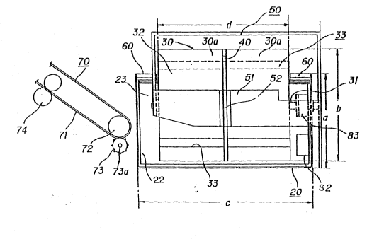
As shown in Figures 1 to 3, a paper slip storage system 10
of the embodiment comprises a paper slip storage container 20
for stacking and storing paper slips transported by a paper slip
transport mechanism 70, a rotation drurn 30 having channels 33,
5 each channel functioning as a temporary housing section, for
receiving paper slips M from the paper slip transport mechanism
70 and rotationally displacing the channels 33 for guiding the
paper slip M house~ in the channel to a paper slip storage position
of the paper slip storage container, paper slip stop members ~0
10 fuhctioning as a separation mechanism for blocking the paper slip
M housed in the channel 33 so that the paper slip does not rotate ~ ~.
further with rotational disptacement of the rotation drum 30 and
for separating the paper slip M from the temporary housing
section at the paper slip storage position of the paper slip
15 storage container 20, and a pair of pressure arm members 40 and
40 functioning as a clamp mechanism for pressing the~ paper slip . . `
M in the channel 33. The paper slip storage system of the .';. .I;
embodiment also has the paper slip transport meohanism 70, ~a ~ .-
controller C which controls the ~rotation operation of the rotation ~ X `~
2 0 ~ drum, and sensors S1 :and S2. The components of the embodiment
are basically installed on a base A.
As shown in Figures 1 and 3, the paper slip storage
container 20 is: a container substantially like a rectangular li,~""" !,~
parallelopiped having sides in the length direction of the ,j'` !j~
2 5 container, one side being higher than the oppositè side,~ a bottom
Z1, and an opening 22 p:ovided in the -pper end of the lower side.
Paper pressure springs 24 are provided inside the container 20.
The paper slip storage container 20 has an internal form which
allows paper slips M such as bills to be housed with the slips
stacked from the bottom 21 up to the oper.ing 22~ and an internal
S sectional area of at least a size which allows the paper slips to ! ', .".~',.`
be housed with the slips spread out. The size af the opening 22 of ~i;c
the paper slip storage container 20 is represented by the length
of the side in the length direction (lateral direction), c, and the
length of the side in the direction (vertical directionj
perpendicular to that sidet a. (See Figure 2.)
A drive mechanism 80 consists of an electric motor 81,
pulleys 82 and 83, and an endless belt 84. The electric motor 81
is fixed to a support bracket B mounted upright on the base A. The
pulley 82 is fixed to a drive shaft 81a of the electric motor 81
and the pulley 83 is fixed to a spindle 31 of the rotation drum 30.
The endless belt 84 is placed on pulleys 82 and 83. The rotation
drum 30 is rotated on the spindle 31 by power from the drive
mechanism 80. "'','.''','".",'.':i.'i!,':`,
The rotation drum 30 is mounted on a frame-like bracket 50
that can be installed on the base A. The frame-like bracket 50 ~.~j
has a top face 51 and sides 53 ar,d 53. The rotation drum 30 is
placed so that the downward portion of a cylindricai face 32
faces the opening 22 of the paper slip storage container 20. Also, ~ "~
the rotation drum 30 is placed with the spindle 31 parallel to the ; ``~
length of the paper slip~storage container 20. The spindle 31 is
supported by the sides 53 and 53 so as to be able to rotate.
.".
A i " ~
.. .... ......... .....
2~372~
~ ~
~ ~ -
As shown in Figure 2, the rotation drum 30 has a diameter b
longer than the vertical length of the paper slip storage container ~ -
20, a, and an axial length d shorter than the lateral length of the
paper slip storage container 20, c. Therefore, in the embodiment, 5
the rotation drum 30 is placed with a radial part of the drum
sticking out from the paper slip storage container 20 in the
~ .. , ~.. , ~
horizontal direction,~ for example, as shown in Figure 3.
In the embodiment, the~ rotation drum 30 comprises two `.;
subdrums 30a and 30a combined on one shaft 31. A clearance for ' ~ ',
10 swingably housing a pair of pressure arm members 40 and 40 is
formed between the subdrums 30a and 30a. The pressure arms 40
and 40 together with a plate member 52 serve as a clamp -
mechanism for restraining paper slips M.
The rotation drums 30 have two axia1 channels 33 and 33 .~.
15 each functioning as a paper slip housin~ section for temporarily
housing a paper slip~M~. The channels 33 each ha~e a~discharge
port 33a opened like a slit on the cylindrical face 32. Each ,'':':''.,''",'"''',!~."`',,
channel 33 is formed over the axial length of the rotation drum ~,`',:',~,",',,''',,,',!,~
30. The channels~ 33 are communicated with one end 35 of the .
20 rotation drum 30 and a taking-in port 36 is formed at the end 35.
The two channels 33 are~at ~ositions symmetrical with each
other with respect to the rotation.
As shown in Figure 3, each channel 33 is located almost ~i"",',,',,,',,.:',j,,,;',;,.,!,
aiong the circumference of the rotation drum 30 from the
25 discharge port 33a to channel bottom 33b. That is, in the
embodiment, the circumference is divided into four equal parts
2 1 ~ 7 2
1 o
`i;, .' ' 'i!~ ~', ' ' '~
and the insides of the circular arcs of the two opposed sectors of
the four parts are used as the channels. The depth is smailer than
the height of a housed paper slip M, but is mad~ so as not to bend
the paper slip. In the embodiment, it is designed to be about two ; .;~5 thirds of the height of a paper slip M.
Each channel 33 is made up of the inner face of the rotation ~`
drum 30 and a separation plate 34a. The rotation drum 30
contains a plurality of radial reinforcing plates 34b formed ~ ~''"""",'''
integrally from the spindle 31 to the cylindrical face 32. The
cylindrical face 32 has a pressure part 32a like a c~rved surface ~
formed on the boundary with the separation plate 34a. '''!j.,',".. '~','.',"i',`''`'
The rotation drum 30 comprises two pressure arm members
40 and 40 corresponding to two channels 33 and 33. Each
pressure arm member 40 Is swingably supported by a shaft 44 In
15 the side of the pressure part 3Za at the inner end face where~the
subdrums 30a and 30a face each other. The pressure arm member
40 holds a paper slip so that it does not slip out of the channel ~$~
The tip of one end of eaoh~ pressure arm member 40 forms a
20 working end 42 for clamping a paper slip M. The working end 42
is displaced~between a hold position for pressing a paper slip M to
the inner wall of the channel 33 and a rélease position ; '~"'.',-''.',!`'~
overlapping the separation plate 34 for releasing the paper slip M. ;
The tip of the other end of each pressure arm member 40 forms a
25 cam end 41 for swingingly displacing the working end 42 between
the hold and release positions. The cam end 41 extends like a
~- -
~:: : : .-. -
1 1 2 1 3 ~2 ~
curve along the cylindrical face 32 and engages a tip 52a of a
plate member 52 (described below) to adjust the swinging of the
working end 42. The cam end 41 is provided so that it can '~
protrude outward from the cylindrical face 32 of the rotation ,~ '~.~,',,
drum 30. ~ " '~
A pin part 43 protrudes in the vicinity of the shaft 44 on the ,,',,
side of one end of each pressure arm member 40. A spring , '~;"' n '
member 45 is extended between each pin member 43, 43 and a hub i, ~,j",~,,,
31a of the spindle 31. The spring member 45 urges the working ,,'' j;' ',;',
end 42 of each pressure arm member 40 in the direction of the '' ' " ,',,';;
release position. ,, ~ ",
The plate member 52 engaging the end margin of the cam ~ ' '' ;'' ''':;
end 41 of the pressure arm member 40 is locked on the top face
51 of the frame-like bracket 50. The end margin of the cam end
41 of the pressure arm member 40 engages the tip 52a of the ~ "~
plate member 52, whereby the cam end 41 of the pressure arm , ' ;`'~'"
member 40 is pushed to the inside of the rotation drum 30 and the
working end 42 is displaced and fixed to the hold position for ;' ,~
temporary regulation, ~, ' ;;','~';~
As shown in Figure 3, the paper slip stop members 60 are
located at position which block passage of a paper slip M housed ,, ~'"~,in the channel 33, on both sides of the rotation drum 30, at the , ;, :~;,"''
upper end of the side of the paper slip storage container 20 from .;
which the rotation drum 30 projects. The paper slip stop member
2 5 60s are at positions, when the rotation drum 30 rotates, strlking
~ against a paper slip M in the channel 33 moving with the rotation ~:
1 2
of the rotation drum 30, thus blocking the movement or the paper
slip M, whereby the paper slip M is stored in the paper slip
- storage container 20.
The paper slip pressure springs 24 are two coil spr;ngs
urging to the opening 22 side so as to press paper slips M in the ~ Q',.,',,'.~. ,',
paper slip storage container 20 towards the rotation drum 30 side
and are located on the full bottom 21 of the paper slip storage ,~
container 20. A paper slip holding plate 23 parallel to the bottom
21 is locked on the top end of the paper slip pressure springs 24.
As shown in Figure 1 and Figure 2, the paper slip transport mechanism
70 has an endless belt 71, pulleys 72, a roller 73, transport
rollers 74, and a paper slip transport passage 75. The endless
belt 71, which is placed on the pulleys 72, is parallel to the
bottom 21 of the paper slip storage container 20 and is slanting. ,
The roller 73 is placed so as to abut against the endless
belt 71 at the position of the pulley 72. It is fixed to a rotation
shaft 73a. Several pairs of transport rollers 74 are placed along
the endless belt 71 with the endless belt 71 between them. The .
paper slip transport passage 75 is formed along the endless belt
71 and communicated with the taking-in port 36 of the channel . ~
33. ~ ::
As shown in Figure 1, a drive 73b such as a motor for
rotationally driving the rotation shaft 73 a is connected to the
rotation shaft 73a. The drive 73b, which is included in the
transport mechanism, is controlled by the controller C (described
;
~. " ' ".'.'`"'
A ~ ;`` ```~````~
1 3
., . ~, ;. ~ ,.
below) for functioning so as to push a paper slip into the channel
33 of the rotation drum 30.
- The sensor S1 consists of a proximity switch, etc., for
sensing whether or not the channel 33 is at a position where a
S paper slip can be received from the transport mechanism.
Specificaily, it can be made of a magnetic sensor, a microswitch,
or the like. To use a magnetic sensor, a magnet or the like is -, .
fitted to a specific position of the end of the drum and when the 1,'.',.''','','',''',',''.',';'$ ,'''.!
magnet reaches the specific position, the magnetic sensor senses
it and detects an~ular displacement of the rotation drum and the . .~ "
position of the channel 33. To use a microswitch, a protrusion is
provided at a specific position of the end of the rotation drum and i;~
when the protrusion reaches the specific position, the
microswitch operates in response to it. .................... ,~`I.
Preferably, at least two sensors S1 are placed at different ~ ilj;'`.!'.
angle positions for accurately stopping the rotation drum 30. ., ~ ,~
That is, preferably the rotation drum can be controlled so that it :;;. ~`
decelerates at the first angle position and stops at the second `
po s lti o n . ""
The sensor S2 is located on the outside of one end of the `~
rotation drum 30, that is, the end of the side where the taking-in
port does not exist for sensing whether or not a paper slip M is
housed in the channel 33. For example, the sensor S2 is made of a ;
photo interrupter. The photo interrupter consists of a light
, . .. . ...
25~ emitting element and a light receiving element opposed to it and i~
detects an obstacle by using the fact that the obstacle would .
-` - 2~3724~
14
hlnder llght from the light emitting element from being incident
on the light receiving element. In the embodiment, a paper slip
corresponds to the obstacle.
A sensor S3 is installed in the paper slip storage container
20 for detecting a given amount of paper slips being housed in the `~
paper slip storage container 20. Specifically, for example, a ~,''.',''.':'~',,,.,,/,''~','~,K''~''
microswitch may be placed on the inner wall of the paper slip l.,.,~,.,,,,.!,
storage container 20 so that when the paper slip pressur~ springs
24 are pressed and displaced and the displacement reaches a
given amount, a part of the spring comes into contact with the ,"'
microswitch .
The controller C is made of, for example, a microcomputer
and controls driving of the drive mechanism 80 of the rotation
drum 30 and the drive 73b of the transport mechanism 70 based ~ ~-
15 on information from the sensors si and~S2.
Next, the function of the embodiment will be discussed.
In Figures 3 to 6, a sequence in which the paper slip storage
system 10 stores paper slips M is shown in stages.
As shown in Figures 1 and 3, when the rotation drum 30
approaches an angle at which the ~channels 33 of the rotation drum
30 become vertical positions, the sensor S1 detects it. When
receiving a detection signal of the sensor S1, the controller C ~ ~
stops the motor 81 of the drive mechanism 80 and starts the ~;
drive 73b of the paper slip transport mechanism 70, whereby a
paper slip M moves together with movement of the endless belt
71 and enters the channel 33 through the taking-in port 36 of the
; ~ `
. . . .
2~372~
. ~,
channel 33, whereby the rotation drum 30 takes the paper slip M
transported on the paper slip transport passage 75 into the
channel 33 through the taking-in port 36 for hlousing it. At this
time, the working end 42 of the pressure arm member 40 ~
S corresponding to the chahnel 33 in which the paper sllp M is ~=
housed is placed at the release position by urging force of the
spring member 45 and therefore the pressure arm member 40 does
not hinder the paper slip M from entering the channel 33. ...
When the paper slip M is housed completely in the channcl
33, the sensor S2 detects it and its detection signal is sent to the
controller C. Upon receipt of the signalj the controller C stops
the drive 73b and starts the drive motor 81.
Next, the drive mechanism 80 shown in Figure 1 causes the
electric motor 81 to rotate the spindle 31 of the rotation drum 30 .
in the arrow direction shown in Figure 3 via the drive shaft 81a, ;~
the pulley 82, the endless belt 84, and the pulley 83 That is, . ~ i~,.`
powered by the drive mechanisms 80, with the paper slip M
housed in the channel 33, the rotation drum 30 rotates on thc ;~
spindle 31 in the dlrection with the channel bottom 33b of the ~;~
channel 33 leading and the taking-in port 33a thereof trailing
(counterclockwise)
When the rotation drum 30 rotates about 45 degrees ~ .
counterclockwise from the angle shown in Figure 3, it will be:
placed at the position shown in Figure 4. At this time, the cam
cnd 41 of the pressure arm member 40 engages the tip 52a of the `~
plate member 52 and is pushed into ~the inside of the rotation: .
2 1 3 7 2 ~
1 6 ;.
drum 30. Therefore, the working end 42 of the pressure arm
member 40 is angularly displaced clockwise on the shaft 44
corresponding to the angular displacement of the pressure arm ~ $
member 40, whereby the working end 42 reaches the hold position
against the urging force of the spring member 45. In this
condition, the working end 42 presses the paper slip M against the `
inner wall of the channel 33 to clamp it, thereby preventing the
paper slip M in the channel 33 from slipping out as the rotation
drum 30 rotates.
Subsequently, when the rotation drum 30 rotates to the :. ;
position shown in Figure 5, the paper slip M caught in the channel
33 is moved to the opening 22 of the paper slip storage container
20 and placed at a position parallel to the paper slip holding plate
23 of the paper slip storage container 20. At this time, the cam
end 41 of the pressure arm member 40 is detached from the tip
52a of the plate member 52. Thus, the working end 42 of the
pressure arm mernber 40 is angularly displaced counterclockwise
on the shaft 44 by the urging force of the spring member 45,
whereby the working end 42 is placed away from the hold position
and reaches the release position, releasing the pressure on the
paper slip M.
Further, when the rotation drum 30 rotates to the angle
shown in Figure 6, the paper slip stop member 60 strikes against
the paper slip M in the channel 33 on the side of the paper slip
25 ~storage container 20 where the rotation drunn 30 protrudes, and
passage of the paper slip M is blocked. As the rotation drum 30 ;
1 7 . ~
further rotates, the channel 33 rotates, but rotation of the paper ~`
slip M is blocked by the paper slip stop member 60, and is thus
- discharged through the discharge port 33a of the channel 33 and
remains in the paper slip storage container 20. ~,
S The paper pressure springs 24 press the paper slips M
stacked in the paper slip storage container 20 towards the side of
the rotation drum 30. When the rotation drum 30 rotates to the `~
angle shown in Figure 6, it presses the paper slip M by means of ~.
the pressure part 32a and puts it between the cylindrical face 32 ~ :'
and the paper slip pressure springs 24 to stack it on the paper ,~
slips M in the paper slip storage container 20. ~ .
Thus, as the rotation drum 30 rotates, the paper slip M
slips out of the discharge port 33a of the channel 33 and is stored
in the paper slip storage container 20. At this time, the paper
slip pressure springs 24 press the paper slips M in the paper slip ,
storage container 20 towards the side of the rotation drum 30,
and thus the paper slips M can be arranged properly. ,;
When the rotation drum 30 rotates 180 degrees from the
angle in Figure 3, the other channel 33 is set to a condition in `, - .` 20 which it can receive another paper slip M from the paper slip
transport mechanism 70. After this, the same operation as
described above is performed.
When the rotation drum 30 thus rotates to stack the paper
slips in the paper slip storage container 20, their weight causes
the springs 24 to be compressed. Compression of the springs .~
`~ causes a part thereof to come in contact with the sensor S3, -~ .
;~ A ~
~ 1 3 7 2 4 ~
:............ 1 8 : ~ ~
~'''~', "''.'
.,~
which then detects it and sends a detection signal to the
controller C. When receiving this signal, the controller C stops -;
the drive 73b and the drive motor 81. When thb paper slips M in
the paper slip storage container 20 are discharged from the
container 20, the same operation as describec~ above is repeated.
Thus, a space for only housing the rotation drum 30 would
; enable the rotation drum 3û to smoothly store paper slips in the
paper slip storage container 20. Therefore, according to the
invention, the installation space of the paper slip storage system
can be made compact for effective use of space such as the inside .
of a gaming machine island in which the paper slip storage ~ ; .
system is installed. 1~
.;,
In the embodiment, the system includes two channels for
housing paper slips, but one or three or more channels may be .
" , - ,
provided. In addition to paper such as bills and slips, flexible ~ ;
cards, etc., may be transported in the place of the paper slips.
Although the rotation drum is used in the embodiment, the
invention is not limited to the drum. The paper slip housing
portion (in the embodiment, the channels) needs only to be able to
be angularly displaced to send a received paper slip to a storage
container at a different angle position. Therefore, a basket or the
like may be used in place of the channel to be rotated.
In the embodiment, the system comprises the rotation drum
divided into two subdrums, but the invention is not limited to it.
For example, a single drum or more than three subdrums can also ~ ;-
be used.
:
21~'~2~
1 9
Although a paper slip is inserted into the channel from the ;
axial direction of the rotation drum in the ennbodiment, it may be
inserted into the channel from the circumferential direction of
the rotation drum. .
S In the embodiment, the pressure arm members 40 and 40 are
used to clamp paper slips M. However, the invention is not
limited to it. For exarnple, pins 91 which can protrude and ~ :
withdraw as desired in the channels 33 and a mechanism, such as
solenoids 92, serving as a drive mechanism For driving protrusion
and withdrawing of the pins are provided, as shown in Figure 8. ~ .
The solenoids 92 are controlled by the controller C so as to
protruded and withdrawn in response to the rotation angle ~- .
positions of the channels. ~i
,.
~. ., ~ ..