Language selection

Search

Patent 2137294 Summary

Third-party information liability

Some of the information on this Web page has been provided by external sources. The Government of Canada is not responsible for the accuracy, reliability or currency of the information supplied by external sources. Users wishing to rely upon this information should consult directly with the source of the information. Content provided by external sources is not subject to official languages, privacy and accessibility requirements.

Claims and Abstract availability

Any discrepancies in the text and image of the Claims and Abstract are due to differing posting times. Text of the Claims and Abstract are posted:

  • At the time the application is open to public inspection;
  • At the time of issue of the patent (grant).
(12) Patent: (11) CA 2137294
(54) English Title: AIM IMPROVING SELF-ALIGNING GOLF SHOES
(54) French Title: CHAUSSURES DE GOLF A SYSTEME DE VISEE
Status: Expired
Bibliographic Data
(51) International Patent Classification (IPC):
  • A43B 5/00 (2006.01)
(72) Inventors :
  • GOLDSTEIN, MARC (United States of America)
(73) Owners :
  • GOLDSTEIN, MARC (United States of America)
(71) Applicants :
(74) Agent: MOFFAT & CO.
(74) Associate agent:
(45) Issued: 1997-07-22
(22) Filed Date: 1994-12-05
(41) Open to Public Inspection: 1995-06-16
Examination requested: 1994-12-05
Availability of licence: N/A
(25) Language of filing: English

Patent Cooperation Treaty (PCT): No

(30) Application Priority Data:
Application No. Country/Territory Date
08/167,339 United States of America 1993-12-15

Abstracts

English Abstract


A pair of golf shoes for aiding a golfer in
establishing an optimal stance and improving the
golfer's aim during driving and iron shots is disclosed.
The golf shoes comprise an upper portion and a sole
portion. The upper portion includes visual alignment
guide lines thereon for aiding a golfer in establishing
relative positioning of the golfer's feet with respect
to each other, the golf ball and the target.


French Abstract

Paire de souliers de golf permettant au golfeur d'avoir un écartement des pieds optimal et d'améliorer sa capacité d'alignement pendant les coups de bois et les coups de fer. Les souliers comprennent une partie supérieure et une semelle. La partie supérieure comporte des lignes d'alignement visuel pour aider le golfeur à placer ses pieds l'un par rapport à l'autre, la balle de golf et la cible dans une position relative.

Claims

Note: Claims are shown in the official language in which they were submitted.

-19-
CLAIMS:
1. A pair of golf shoes (20A, 20B; 40A, 40B;
60A, 60B; 70A, 70B; 80A, 80B; 86A, 86B) characterized by
an upper portion (24A, 24B; 42A, 42B; 72A, 72B; 82A,
82B; 92A, 92B) and a sole portion (26A, 26B; 74A, 74B),
said upper portions of each of said pair of golf shoes
including a central longitudinal axis (LA, RA; LA'; RA')
extending lengthwise through the center thereof and
alignment means (28A, 28B, 30A, 30B; 44A, 44B, 46A, 46B,
48A, 48B, 50A, 50B; 76A, 76B; 84A, 84B; 88A, 88B)
arranged on said upper portion (24A, 24B; 42A, 42B; 72A,
72B; 82A, 82B; 92A, 92B) of at least one of said golf
shoes for aiding a golfer (22) in establishing relative
positioning of the golfer's feet with respect to a
target, the ball and to each other so that an optimal
stance may be obtained to improve a golfer's aim during
driving and iron shots, said alignment means (28A, 28B,
30A, 30B; 44A, 44B, 46A, 46B, 48A, 48B, 50A, 50B; 76A,
76B; 84A, 84B; 88A, 88B) including indicia having a
orientation offset from a corresponding one of said
central longitudinal axes (LA, RA; LA'; RA'), and at
least one first straight line (28B, 30B; 44B, 46B, 48B,
50B; 76B, 78B; 84B; 88B) arranged on said upper portion
(24B; 42B; 72B; 82B; 92B) of a right one (20B; 40B; 60B;
70B; 80B; 86B) of said pair of golf shoes and at least
one second straight line (28A, 30A; 44A, 46A, 48A, 50A;
76A, 78A; 84A; 88A) arranged on said upper portion (24A;
42A; 72A; 82A; 92A) of a left one (20A; 40A; 60A; 70A;
80A; 86A) of said pair of golf shoes, said at least one
first straight line and said at least one second
straight line defining corresponding first and second
axes, said first and second axes being disposed to
intersect each other when said right and left golf shoes
(20A, 20B; 40A, 40B; 60A, 60B; 70A, 70B; 80A, 80B; 86A,
86B) are placed parallel to each other, and are arranged
parallel to each other to indicate when the golfer's
feet are placed in the optimal stance.

-20-
2. The golf shoes (20A, 20B; 40A, 40B; 60A,
60B; 70A, 70B; 80A, 80B; 86A, 86B) of claim 1
characterized in that said alignment means includes a
first set of perpendicular longitudinal and transverse
linear indicia (28B, 30B; 44B, 46B, 48B, 50B; 76B, 78B)
arranged on said upper portion of a right one (20B; 40B;
60B; 70B; 80B; 86B) of said pair of golf shoes, and a
second set of perpendicular longitudinal and transverse
linear indicia (28A, 30A; 44A, 46A, 48A, 50A; 76A; 78A)
arranged on said upper portion of a left one (20A; 40A;
60A; 76A; 80A; 86A) of said pair of golf shoes, said
first and second sets of perpendicular linear indicia
being offset from each other when said central
longitudinal axes (LA, RA; LA', RA') of said left and
right golf shoes are placed parallel to each other, and
said first and second sets of perpendicular linear
indicia (28A, 28B, 30A, 30B; 44A, 44B, 46A, 46B, 48A,
48B, 50A, 50B; 76A, 76B, 78A, 78B) being arranged such
that the respective longitudinal and transverse linear
indicia thereof are parallel to each other when the
golfer's feet are placed in the optimal stance.
3. The golf shoes (20A, 20B; 40A, 40B; 60A,
60B; 70A, 70B; 80A, 80B; 86A, 86B) of claim 2
characterized in that each of said first and second sets
of perpendicular longitudinal and transverse linear
indicia (28A, 28B, 30A, 30B; 44A, 44B, 46A, 46B, 48A,
48B, 50A, 50B; 76A, 76B, 78A, 78B) comprises one
longitudinal line (28A, 28B; 76A, 76B) and one
transverse line (30A, 30B; 78A, 78B).
4. The golf shoes (20A, 20B; 40A, 40B; 60A,
60B; 70A, 70B; 80A, 80B; 86A, 86B) of claim 2
characterized in that each of said first and second sets
of perpendicular longitudinal and transverse linear
indicia (28A, 28B, 30A, 30B; 44A, 44B, 46A, 46B, 48A,
48B, 50A, 50B; 76A, 76B, 78A, 78B) comprises a plurality
of transverse lines (44A, 44B, 46A, 46B, 48A, 48B).
5. The golf shoes (20A, 20B; 40A, 40B; 60A,
60B; 70A, 70B; 80A, 80B; 86A, 86B) of claim 1

-21-
characterized in that said at least one first straight
line (28B) is offset from said central longitudinal axis
(RA) of said right golf shoe (20B) at an angle of about
22-1/2°, and wherein said at least one second straight
line (28A) extends coaxial with said central
longitudinal axis (LA) of said left golf shoe (20A) so
that a left handed golfer (22) can obtain the Hogan
stance upon placement of said golf shoes in the optimal
position.
6. The golf shoes (20A, 20B; 40A, 40B; 60A,
60B; 70A, 70B; 80A, 80B; 86A, 86B) of claim 1
characterized in that said at least one second straight
line is offset from said central longitudinal axis (LA)
of said left golf shoe (60A) at an angle of about 22-1/2°,
and wherein said at least one first straight line
extends coaxial with said central longitudinal axis (RA)
of said right golf shoe (60B) so that a right handed
golfer can obtain the Hogan stance upon placement of
said golf shoes in the optimal position.
7. The golf shoes (20A, 20B; 40A, 40B; 60A,
60B; 70A, 70B; 80A, 80B; 86A, 86B) of claim 1
characterized in that said at least one first straight
line (76B) is offset from said central longitudinal axis
(RA') of said right golf shoe (70B) at an angle of about
27-1/2°, and wherein said at least one second straight
line (76A) is offset from said central longitudinal axis
(LA') of said left golf shoe (70A) at an angle of about
27-1/2° so that a golfer (22) can obtain the Leadbetter
stance upon placement of said golf shoes in the optimal
position.
8 The golf shoes (20A, 20B; 40A, 40B; 60A,
60B; 70A, 70B; 80A, 80B; 86A, 86B) of claim 1
characterized in that said alignment means includes
connection means (94A, 94B) for selective attachment and
detachment to said upper portion of said golf shoes.
9. The golf shoes (20A, 20B; 40A, 40B; 60A,
60B; 70A, 70B; 80A, 80B; 86A, 86B) of claim 1 further
characterized in that a shield (94A, 94B) including


- 22 -

means for detachably connecting said shield to said upper
portion of said golf shoes.
10. The golf shoes (20A, 20B; 40A, 40B; 60A,
60B; 70A, 70B; 80A, 80B; 86A, 86B) of claim 9
characterized in that said shield includes putting
alignment means (94A) arranged thereon for facilitating
alignment of a golf ball and a selected one of the golf
shoes to optimize a golfer's aim during putting.
11. The golf shoes (20A, 20B; 40A, 40B; 60A,
60B; 70A, 70B; 80A, 80B; 86A, 86B) of claim 10
characterized in that said putting alignment means (94A)
includes at least one longitudinal line arranged on said
upper portion of at least one of said golf shoes whereby
the golfer's aim is optimized by aligning said at least
one longitudinal line with a golf ball prior to putting.
12. The golf shoes (20A, 20B; 40A, 40B; 60A,
60B; 70A, 70B; 80A, 80B; 86A, 86B) of claim 11
characterized in that said putting alignment means (94A)
further includes at least one transverse line
perpendicular to said at least one longitudinal line
arranged on said upper portion (92A).

Description

Note: Descriptions are shown in the official language in which they were submitted.


~37294
~ --1--
AIM IMPROVING SELF-ALIGNING GOLF SHOES
The present invention relates to a device for
optimizing a golf stance to improve a golfer's aim.
More particularly, the present invention relates to
self-aligning golf shoes which enable a player to obtain
an optimal stance and thus, improved aim during driving
and iron shots.
Golf has been a popular sport throughout the
world for many years. Its popularity has been steadily
increasing both in the United States and abroad. As
such, golfers have continuously strived to lower their
scores by increased practice time and by purchasing
various accessories which may give them advantageous
results over competing players.
One particular area which golfers continuously
strive to improve is their aim. Although the golf swing
is made up of several elements including initially
obtaining a proper stance, concentration during the
downswing, proper shifting of a player's weight and the
follow through, the basis for achieving a successful
golf swing and accurate aim is first obtaining an
optimal stance. As evidenced by the crowded nature of
the golf training art, inventors have expended great
efforts in developing golf swing training aids and aim
improvement devices including devices for aiding golfers
in obtaining a proper stance during driving and iron
shots.
Despite the crowded nature of the prior art,
all of the known devices have drawbacks which render
them undesirable or illegal for use during play. In
this regard, several known golf training devices include
a wedge-shaped device which is adapted to be connected
to the outer portion of the sole of a golfer's shoe.
These illegal devices are generally used to cant one of
the golfer's feet to facilitate proper shifting of a
golfer's body weight during the swing. Such devices are
disclosed in U.S. Patent Nos. 4,819,940 to Davis and
4,073,375 to O'Brien.
*

213~94
_ -2-
Still other attempts at improving a golfer's
stance are evidenced by prior art devices that are
adapted to be fastened to the heel of a golf shoe, such
as the illegal device disclosed in U.S. Patent No.
5,150,903 to Percic.
The prior art also includes inserts for golf
shoes which cause a golfer's foot to be canted either to
the left or to the right for the purpose of improving a
golfer's balance by shifting of the golfer's body weight
and body position during a golf swing. Examples of the
illegal insert-type devices are disclosed in U.S. Patent
Nos. 5,212,894 to Paparo and 4,953,311 to Bruggemeier.
External feet positioning indicators which may
be useful for illustrating the proper positioning of a
golfer's feet during practice, have also been proposed
to aid a golfer in obtaining an optimal stance. These
devices are not generally used during play as they are
too awkward to carry around for use on a golf course.
Examples of such devices are disclosed in U.S. Patent
Nos. 3,229,981 to Taber and 3,122,846 to Trent.
Putting aids have also been disclosed in the
prior art to facilitate the alignment of a golf shoe
with a golf ball so that a golfer's putting ability may
be enhanced. An example of such a device is disclosed
in U.S. Patent No. 2,503,586 to Miller. Although this
device may be useful for putting purposes, it has no use
whatsoever for driving and iron shots as it does not
facilitate positioning of the golfer's feet relative to
each other.
All of the foregoing prior art devices which
are intended to improve a golfer's swing during driving
and iron shots, have the major drawback of being illegal
under PGA rules. In particular, the PGA rules do not
permit golfers to use any physical aids for improving
their swing to lower their golf score.
The present invention solves the
aforementioned drawbacks of the prior art by providing
means for aiding a golfer in obtaining an optimal golf

213~294
_ -3-
stance during driving and iron shots so that the
golfer's aim may be improved. Additionally, the present
invention is useful during practice and official play,
as it meets all requirements of the PGA rules.
One aspect of the present invention pertains
to a pair of golf shoes for aiding a golfer in
establishing relative positioning of his or her feet
with respect to the ball and with respect to each other
so that an optimal stance may be obtained to improve the
golfer's aim during driving and iron shots. Each of the
golf shoes comprises an upper portion and a sole
portion. The upper portion of each of the golf shoes
includes a central longitudinal axis extending
lengthwise through the center thereof and alignment
means arranged on the upper portion of at least one of
the golf shoes. The alignment means may include indicia
having a predetermined orientation offset from a
corresponding one of the central longitudinal axes.
The one preferred embodiment, the alignment
means of the golf shoes may include a first set of
perpendicular longitudinal and transverse linear indicia
arranged on the upper portion of the right golf shoe,
and a second set of perpendicular longitudinal
transverse linear indicia arranged on the upper portion
of the left golf shoe. The first and second sets of
perpendicular linear indicia are preferably offset from
each other when the central longitudinal axis of the
left and right golf shoes are placed parallel to each
other. When the golfer's feet are placed in the optimal
stance, the first and second sets of perpendicular
linear indicia are adapted to be arranged such that the
respective longitudinal and transverse linear indicia
thereof are placed parallel to each other. The first
and second sets of perpendicular longitudinal and
transverse linear indicia may comprise one longitudinal
line and one transverse line, or may comprise a
plurality of longitudinal or transverse lines.
Preferably, the one or more transverse lines will be in

2137294
_ -4-
alignment with the intended target area when the golf
shoes are arranged in the optimal position.
In another preferred embodiment, the alignment
means of the golf shoes includes at least one first
straight line arranged in a predetermined position on
the upper portion of the right golf shoe, and at least
one second straight line arranged in a predetermined
position on the upper portion of the left golf shoe.
The at least one first straight line and the at least
one second straight line define corresponding first and
second axes which are disposed to intersect each other
when the golf shoes are placed parallel to each other,
and are adapted to be arranged parallel to each other
when the golfer's feet are placed in the optimal stance.
In still another preferred embodiment, the at
least one second straight line may be offset from the
central longitudinal axis of the left golf shoe at an
angle of about 22-1/2, and the at least one first
straight line is arranged to extend coaxial with the
central longitudinal axis of the right shoe so that a
right handed golfer can obtain the Hogan stance upon
placing of the golf shoes in the optimal position.
In still another preferred embodiment, the at
least one first straight line would be offset from the
central longitudinal axis of the right golf shoes at an
angle of about 22-1/2, and the at least one second
straight line is arranged to extend coaxial with the
central longitudinal axis of the left golf shoe so that
a left handed golfer can obtain the Hogan stance upon
placement of the golf shoes in the optimal position.
In another preferred embodiment, the at least
one first and second straight lines may be offset from
corresponding ones of the central longitudinal axes of
the respective left and right golf shoes at an angle of
about 27-1/2 so that a golfer can obtain the Leadbetter
stance upon placement of the golf shoes in the optimal
position.

21372~
_ -5-
The alignment means of the golf shoes of the
present invention may also include connection means for
selective attachment and detachment to corresponding
upper portions of the golf shoes.
According to another preferred embodiment, the
golf shoes of the present invention may comprise
detachable shield means connectable to the upper portion
of the golf shoes for selectively covering the alignment
means thereon. The detachable shield means may include
putting alignment means arranged thereon for
facilitating alignment of a golf ball in a selected one
of the golf shoes to optimize a golfer's aim during
putting. The putting alignment means may include at
least one longitudinal line arranged on the upper
portion of at least one of the golf shoes whereby the
golfer's putting stroke is optimized by aligning the at
least one longitudinal line with a golf ball prior to
putting. The putting alignment means may also include
at least one transverse line perpendicular to the at
least one longitudinal line.
An alternate preferred embodiment, the
detachable shield means may include an arbitrary design,
or may not include any indicia whatsoever.
According to another aspect of the present
invention, a method is disclosed for aiding a golfer in
selecting an optimal stance to maximize the golfer's aim
during driving and iron shots. One preferred method
comprises the steps of selecting a desired location in
which to place the golfer's feet with respect to a golf
ball; utilizing alignment means including indicia
arranged on the upper portion of golf shoes to select
positions in which to place a golfer~s feet relative to
a target, each other and to the golf ball, and placing
both feet in the selective position so that the
alignment means will indicate when an optimal stance has
been obtained.
Preferably, the alignment means according to
the preferred method comprises a plurality of alignment

2137294

_ -6-
lines, and the step of placing both feet in the selected
positions comprises arranging the golf shoes in a
relative position with respect to each other so that
respective ones of the plurality of lines of each of the
golf shoes are arranged parallel to each other and to a
central reference axis extending perpendicular to an
axis which extends between the golfer's feet and the
target.
In another preferred embodiment, the plurality
of alignment lines may comprise a pair of perpendicular
lines arranged on each of the golf shoes, and the step
of arranging the golf shoes in a relative position with
respect to each other comprises aligning respective ones
of the pair of perpendicular lines with each other so
that longitudinal and transverse lines thereof extend
parallel to each other and with the central reference
axis ext~;ng perpendicular to an axis which extends
between the golfer's feet and the target. In this
preferred embodiment, the transverse lines may be
arranged in a predetermined position so that they are
placed in alignment with a target area when an optimal
stance has been obtained.
Accordingly, it is an object of the present
invention to provide a pair of golf shoes including
means for aiding an golfer in obtaining a optimal stance
during driving and iron shots so that the golfer's aim
may be improved. It is a further object of the present
invention to provide a pair of golf shoes which may be
used to aid a golfer in obtaining an optimal stance
during driving and iron shots that meet all of the
requirements of the PGA so that they can be used during
official play.
It is still another object of the present
invention to provide a pair of golf shoes including
means for placing them in a relative position with
respect to a target, each other and with respect to a
golf ball to aid a golfer in obtaining an optimal stance
during driving and iron shots.

2137294
_ -7-
The above Summary as well as further objects,
features, and advantages of the present invention will
be more fully understood with reference to the following
detailed description of the self-aligning golf shoes,
when taken in conjunction with the accompanying drawings
described below.
In order that the invention may be fully
understood, it will now be described with reference to
the accompanying drawings, in which:
FIG. 1 is a top plan view of one preferred
embodiment of the golf shoes of the present invention
for a right handed player before assuming a desired
stance.
FIG. 2 is a top plan view of the golf shoes
shown in FIG. 1 after the player's feet are placed in
the desired stance.
FIG. 3 is a perspective view of the golf shoes
shown in FIG. 2 in use by a golfer.
FIG. 4 is a top plan view of a second
preferred embodiment of the golf shoes of the present
invention for a right handed player after the player's
feet are placed in the desired stance.
FIG. 5 is a top plan view of a third preferred
embodiment of the golf shoes of the present invention
for a left handed player before assuming a desired
stance.
FIG. 6 is a top plan view of the golf shoes
shown in FIG. 5 after the player's feet are placed in
the desired stance.
FIG. 7 is a top plan view of a fourth
preferred embodiment of the golf shoes of the present
invention for both right and left handed players before
assuming a desired stance.
FIG. 8 is a top plan view of the golf shoes
shown in FIG. 7 after the player's feet are placed in
the desired stance.

2137294
_ -8-
FIG. 9 is a perspective view of the golf shoes
shown in FIG. 7 in use by a golfer after the golfer~s
feet are placed in the desired stance.
FIG. 10 is a perspective view of a fifth
preferred embodiment of the golf shoes of the present
invention for both right and left handed players in use
by a golfer after the golfer's feet are placed in the
desired stance.
FIG. 11 is a perspective view of a sixth
preferred embodiment of the golf shoes of the present
invention for both right and left handed players in use
by a golfer after the golfer's feet are placed in the
desired stance.
FIG. 12 is an exploded perspective view of a
sixth embodiment of the golf shoes of the present
invention illustrating optional removable shields.
In accordance with one preferred embodiment of
the present invention, a pair of golf shoes including a
left golf shoe 20A and a right golf shoe 20B are
generally shown in FIGS. 1-3. The golf shoes are
intended to be worn by a golfer 22 to facilitate
consistently achieving an optimal stance to improve the
golfer's aim during driving and iron shots.
As discussed in this application, the terms
~driving and iron shots~ are intended to include all
shots made with drivers, traditional irons including No.
2-9 irons, a pitching wedge, and all clubs useful for
chipping shots. Thus, driving and iron shots include
golf shots made with all clubs except putters.
It should be understood that the golf shoes of
the present invention are intended to be used as an aid
by golfers of all skill levels in acquiring an
appropriate stance prior to hitting a golf ball. In
this regard, the golf shoes disclosed in FIGS. 1-9
include visual lines thereon to indicate when a golfer
22 has obtained one of two popular golf stances, i.e.,
the Hogan and Leadbetter stances. However, these
stances are merely preferred stances in accordance with

21372~4
~ g

the preferred embodiments of the present invention and
thus, are only intended to be examples of stances that
may be obtained with the golf shoes of the present
invention. Thus, the alignment lines on the golf shoes
can be arranged in various positions to indicate when
different preferred stances are obtained.
The golf shoes shown in FIGS. 1-3 are useful
to help players of all skill levels to obtain the
popular Hogan stance during driving and iron shots. The
left golf shoe 20A includes an upper portion 24A and a
sole portion 26A. Similarly, the right golf shoe 20B
includes an upper portion 24B and a sole portion 26B.
Thus, the support structure of the golf shoes of the
present invention include the same basic components,
i.e., a sole and an upper portion, as most of the
athletic footwear that is already commercially
available.
In the preferred embodiment shown in FIGS. 1-
3, the left golf shoe 20A includes a longitudinal guide
line 28A and a transverse guide line 30A. The
transverse guideline 30A is arranged perpendicular to
the longitudinal guide line 28A. A central longitudinal
axis LA extends through the longitudinal center of the
left golf shoe 2OA as shown in phantom in FIG. 1.
The right golf shoe 20B also includes a pair
of guide lines arranged on the upper portion 24B. In
this regard, the right golf shoe 2OB includes a
longitudinal guide line 28B and a transverse guide line
30B arranged perpendicular thereto. Additionally, a
central longitudinal axis RA is co-axially aligned with
the longitudinal guide line 28B of the right golf shoe
20B.
The sole portions 26A and 26B of the
respective left and right golf shoes may be made of a
rubber material. However, the material of which the
sole portions 26A and 26B are made is not essential to
the patentable aspects of the present invention and
thus, may comprise other suitable materials such as

213729~
--10--
leather, rubber, plastic and the like. Similarly, the
left and right upper portions 24A and 24B may be made of
various material including leather, synthetic leather,
canvas, vinyl, etc. The guide lines 28A and 30A of the
left golf shoe 20A and the guide lines 28B and 30B of
the right golf shoe 20B are intended to act as alignment
means to provide a visual aid for a golfer 22 in
establishing relative positioning of the golfer's feet
relative to each other and to the ball so that an
optimal stance may be obtained to improve the golfer's
aim during driving and iron shots. The manner in which
this will be accomplished will be discussed in detail
below.
It should be appreciated that the guide lines
in all embodiments of the present invention may be
arranged on the upper portions 24A and 24B of the left
and right golf shoes in any suitable manner. For
example, the guide lines may be placed on the upper
portion of the golf shoes by various colored dyes, sewn
material, separable snap-on devices or loop and hook
velcro connectors. These different ways of placing the
guide lines on the upper portion of the golf shoes are
intended to be examples only. Thus, the particular
manner in which the guide lines are arranged on golf
shoes is not intended to be limited by the description
in this application. What is important, is that the
guide lines are arranged in a manner that will clearly
provide a visual aid to a golfer who wishes to obtain a
particular stance.
As discussed above, the golf shoes 20A, 20B
disclosed in FIGS. 1-3 are intended to aid a right
handed golfer in establishing the Hogan stance during
driving and iron shots. This is accomplished by
arranging the longitudinal guide line 28A of the left
golf shoe 20A in a position so that it will intersect
the central longitudinal axis LA to form an angle of
approximately 22-1/2 therewith on the anterior side of
the left golf shoe 20B, i.e., the side closest to the

213729~
--11--
right golf shoe as shown in FIG. 1. The relative
positioning of the longitudinal guide line 28A and the
transverse guide line 30A is fixed. In the embodiment
shown in FIGS. 1-3, the longitudinal guide line 28A will
always remain perpendicular to the transverse guide line
30A regardless of the positioning of the left foot golf
shoe 20A. The longitudinal guide line 28B and the
transverse guide line 30B of the right golf shoe 20B
will also be perpendicular to each other at all times.
The longitudinal guide line 28B of the right
golf shoe 20B extends coaxial with the central reference
axis RA . As with the left golf shoe 2 OA, the transverse
guide line 30B of the right golf shoe 20B will always
remain perpendicular to the corresponding longitudinal
guide line 28B.
FIG. 2 illustrates an isolated top plan view
of the left and right golf shoes after a right handed
golfer 22 has obtained the Hogan stance in accordance
with a preferred embodiment of the present invention.
As clearly shown in FIG. 2, the left golf shoe 20A
should be placed at an angle with respect to the right
golf shoe 20B until the longitudinal guide line 28A and
the transverse guide line 30A arranged on the upper
portion 24A are in axes which extend parallel with the
respective longitudinal guide line 28B and the
transverse guide line 30B on the upper portion 24B of
the right golf shoe 20B. When the respective left and
right longitudinal and transverse guide lines are in
alignment with each as shown in FIG. 2, the golfer 22
has a clear indication that he or she has obtained the
desired stance.
In practice, a golfer will place his or her
feet at a particular distance from a golf ball 32 prior
to assuming an appropriate stance. The relative
positioning of a golfer's body and feet with respect to
the golf ball 32, and with respect to each other and the
target, is shown in FIG. 3 which generally illustrates a

2137~9~
-12-
golfer 22 who has used the golf shoes of the present
invention to establish the popular Hogan stance.
For a right handed golfer, the golf ball 32
should be lined up with a desired location on the
golfer's body along a central reference axis CA as shown
in FIG. 3. Of course, different individuals will have
different preferences with regard to the alignment
between the golf ball 32 and a selected position on his
or her body. For example, some right-handed golfers may
prefer to align the golf ball 32 with his or her left
armpit, while other golfers may align the golf ball with
his or her left heel or other location. Of course, for
a left handed golfer, the body position is reversed so
that the golf bal' 32 is generally arranged in alignment
with a location on the right side of the golfer's body
(not shown). Once this initial alignment is obtained,
the golfer must determine how to achieve the optimal
stance. The present invention accomplishes this by
clearly providing the golfer 22 with a visual aid for
arranging his or her feet in a relative position with
respect to the target, each other and with respect to
the golf ball 32. Once the longitudinal and transverse
guide lines are aligned, the golfer knows that the
optimal stance has been obtained and may begin his or
her swing.
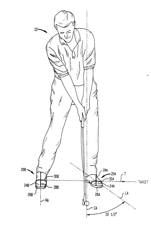
As further shown in FIG. 3, when the golfer
22 has been properly positioned in the Hogan stance, the
longitudinal guide line 28A of the left golf shoe 20A
will intersect the central reference axis CA at an angle
of 22-1/2 in at least one quadrant. On the other hand,
the longitudinal guide line 28B of the right golf shoe
20B will extend parallel to the central reference axis
CA. The angular relationship between the left and right
longitudinal guide lines is thus the same with respect
to the longitudinal reference axes LA and RA, and the
central reference axis CA.
Additionally, the transverse guide lines 30A
and 30B are particularly useful to aid a golfer 22 in

2137234
--13--
improving his aim prior to swinging a golf club. In
this regard, the arrangement of the transverse guide
lines 30A and 30B are selected so that their aligned
axis, obtained when the optimal stance is obtained, is
also in alignment with the intended target area. This
feature of the present invention can be appreciated from
FIG. 3 which illustrates that the axis of the aligned
transverse lines 30A and 30B aids the golfer 22 in
aiming toward the target area along arrow T. When the
golfer 22 has obtained an optimal stance, the central
reference axis CA will extend perpendicular to the axis
of target arrow T which extends through the transverse
guide lines 30A and 30B between the golfer's feet and
the target.
FIG. 4 depicts an alternate embodiment of the
present invention which includes a plurality of
transverse lines 44A, 46A and 48A on the upper portion
42A of the left golf shoe 40A and a plurality of
transverse lines 44B, 46B and 48B on the upper portion
42B of the right golf shoe 40B. These additional
transverse lines may provide a golfer with a clearer
reference site than that provided by the single
transverse line embodiment establishing the desired
stance. One longitudinal line 50A, 50B is shown on the
respective left and right golf shoes in the embodiment
of FIG. 4. However, more or less transverse or
longitudinal lines may be used for aesthetic purposes to
create a different appearance on the upper portions of
the golf shoes.
FIGS. 5 and 6 illustrate a further embodiment
of the present invention for use by left-handed golfers
who also prefer the Hogan stance. In this regard, the
longitudinal and transverse guide lines on the left and
right golf shoes 60A and 60B are simply arranged in an
orientation opposite to that shown for a right-handed
golfer in FIGS. 1-3. Thus, in the embodiments shown in
FIGS. 5 and 6, a left-handed golfer would be required to
turn his or her right foot away from the left foot to

2137~94
-14-
form an angle of approximately 22-1/2 with respect to a
central axis between a golf ball and a selected location
on a golfer's body as discussed above.
A second preferred stance which may be
obtained by using the golf shoes of the present
invention is the popular Leadbetter stance. When the
Leadbetter stance is used, the positioning of a golfer's
feet is the same for left and right handed players.
FIGS. 7-9 clearly illustrate the orientation of the
alignment guide lines required to help a golfer obtain
the Leadbetter stance. In this regard, FIG. 7
illustrates an isolated top plan view of a further
preferred embodiment of the present invention in which
the alignment guide lines are shown in their orientation
prior to positioning a golfer's feet in the Leadbetter
stance. FIG. 8 depicts the orientation of the alignment
guide lines after the golfer's feet have been moved into
the proper position to obtain the Leadbetter stance. In
this stance, both the left and the right feet should be
turned outwardly from each other at an angle of
approximately 27-1/2 with respect to a central
reference axis CA' (shown in phantom).
In accordance with this embodiment, a left
golf shoe 70A includes an upper portion 72A and a sole
portion 74A. A longitudinal line 76A and a transverse
line 78A are arranged on the upper portion 72A. The
longitudinal line 76A forms an angle of about 27-1/2
with respect to the anterior side of a central
longitudinal axis LA' (shown in phantom). Similarly,
the right golf shoe 70B includes an upper portion 72B
and a sole portion 74B. A longitudinal line 76B and a
transverse line 78B are arranged on the upper portion
72B. The longitudinal line 76B of the right golf shoe
70B also forms a angle of approximately 27-1/2 with
respect to the central longitudinal axis RA' (also shown
in phantom), all of which can be appreciated from FIGS.
7 and 8. The orientation of the alignment lines shown
in FIG. 7 is that which would be seen in the Leadbetter

- 2137294
-~ -15-
style golf shoes while the golfer has his or her feet
placed in a normal standing position, i.e., before
assuming the Leadbetter stance.
Once the Leadbetter stance is obtained, the
longitudinal line 76A and the transverse line 78A of the
right golf shoe 70 will appear to be parallel with the
respective longitudinal line 76B and the transverse line
78B of the right golf shoe 70B as shown in FIGS. 8 and
9. As further shown in FIG. 9, when the golfer 22 has
successfully obtained the Leadbetter stance, the aligned
transverse lines 78A and 78B will be arranged in an
imaginary axis including the target arrow T. Thus,
providing the golfer 22 with a means for improving his
or her aim prior to swinging the golf club.
Although the particular positioning of a
golfer's feet will vary in accordance with the desired
stance in the various preferred embodiments, the
alignment guide lines of the present invention operate
in a similar manner for each of the embodiments of the
present invention. That is the longitudinal lines and
the transverse lines, if any, should be placed in a
parallel position with respect to the corresponding
longitudinal or transverse lines on the other golf shoe.
This is beneficial as a beginning golfer may wish to
experiment with various stances before selecting one
that is the most comfortable. Thus, a golfer may
purchase both the Leadbetter and Hogan style golf shoes
of the present invention and will only need to
understand that the longitudinal and transverse lines on
the respective left and right golf shoes must be
arranged parallel to each other to indicate that the
desired optimal stance has been obtained.
It should be appreciated that the number of
longitudinal and transverse lines may vary in alternate
emhoAiments while still coming within the scope of the
present invention. In this regard, FIG. 10 discloses
another preferred embodiment of the golf shoes of the
present invention that is intended to help a golfer 22

~1~7294
-16-
consistently obtain the Leadbetter stance. In this
embodiment, the left golf shoe 80A includes a single
longitudinal line 84A on an upper portion 82A thereof
and a right golf shoe 80B also includes a single
longitudinal line 84B arranged on an upper portion 82B.
There are no transverse lines required to achieve
alignment of the golf shoes in this embodiment. This
embodiment may be desirable for golfers who have a good
~eye~ and can easily determine that the longitudinal
lines 84A and 84B are arranged parallel to each other
without the additional aid of transverse lines to
accurately determine that an appropriate stance, such as
the Leadbetter stance, has been obtained.
FIG. 11 illustrates a further embodiment of
golf shoes of the present invention which may be used to
aid a golfer 22 in obtaining the Leadbetter stance. In
accordance with this embodiment, the left shoe 86A and
the right shoe 86B include corresponding transverse
lines 88A and 88B, respectively. When proper
positioning has been achieved, the transverse guide
lines 88A and 88B will be arranged parallel to each
other and will be placed in a common axis pointing to
the target as evidenced by arrow T. Unlike the
embodiments of FIGS. 7-10, no longitudinal lines are
needed to obtain proper alignment. However, similar to
the embodiments of FIGS. 7-10, the golf shoes of FIG. 11
may also be desirable for use by golfers who can
determine when the transverse guide lines 88A and 88B
are parallel to each other, without relying on
perpendicular longitudinal lines, to verify that an
optimal Leadbetter stance has been obtained. Thus, the
golf shoes of FIGS. lo and 11 may be particularly
desirable to golfers who have a relatively high
experience level and are thus capable of quickly
determining that they have established the appropriate
stance.
In yet a further preferred embodiment (not
shown) golf shoes for aiding a right-handed golfer in

213729~
- -17-
establishing the Hogan stance, may not have any lines
whatsoever on the right golf shoe and may only include a
single longitudinal or transverse line on the left golf
shoe. In such an embodiment, the present invention will
indicate to an advanced golfer that the Hogan stance has
been obtained when the solitary longitudinal or
transverse line is arranged parallel to an imaginary
longitudinal or transverse axis through the right golf
shoe. Such an embodiment may be desirable to golfers
who do not wish to wear golf shoes including a plurality
of lines as disclosed in the various other embodiments
of the present invention.
FIG. 12 discloses another preferred embodiment
of the present invention. In this regard, optional
removable shields 94A and 94B are disclosed as being
selectively attachable and detachable with respect to
the upper portions 92A and 92B of left and right golf
shoes 90A and 90B, respectively. The shield 94A of the
left golf shoe 90A includes a longitudinal line 96A and
a perpendicular transverse line 98A which may serve as
an alignment means for a right-handed player during
putting. Corresponding hook and loop velcro connectors
lOOA may be used to connect the removable shield to the
upper portion 92A of the left golf shoe 90A. The right
golf shoe 90B is also equipped with a hook and loop
velcro connecting means lOOB for optionally attaching a
shield 94B over the alignment lines on the upper portion
92B thereof. The right shield 94B is shown in FIG. 10
as having a solid appearance with no design whatsoever
so that a golfer can cover the alignment lines of the
upper portion 92B of the right golf shoe to avoid any
distraction during putting. Additionally, in alternate
embodiments, both of the removable shields 94A and 94B
may have a solid appearance for experienced golfers who
no longer need the alignment means of the present
invention as an aid in establishing a desired stance and
improved aim.

- ~ 37~94
- -18-
While the foregoing description and figures
are directed toward the preferred embodiments in
accordance with the present invention, it should be
appreciated that numerous modifications can be made to
the structure and orientation of the alignment guide
lines on the golf shoes. Thus, such modifications in
the materials, structure and arrangement of the
disclosed embodiments and the steps of the method of the
present invention can be made without departing from the
spirit and scope thereof. Accordingly, the foregoing
description of the preferred embodiments should be taken
by way of illustration rather than by way of limitation
with respect to the present invention, which is defined
by the claims set forth below.

Representative Drawing
A single figure which represents the drawing illustrating the invention.
Administrative Status

For a clearer understanding of the status of the application/patent presented on this page, the site Disclaimer , as well as the definitions for Patent , Administrative Status , Maintenance Fee  and Payment History  should be consulted.

Administrative Status

Title Date
Forecasted Issue Date 1997-07-22
(22) Filed 1994-12-05
Examination Requested 1994-12-05
(41) Open to Public Inspection 1995-06-16
(45) Issued 1997-07-22
Expired 2014-12-05

Abandonment History

There is no abandonment history.

Payment History

Fee Type Anniversary Year Due Date Amount Paid Paid Date
Application Fee $0.00 1994-12-05
Maintenance Fee - Application - New Act 2 1996-12-05 $50.00 1996-10-16
Maintenance Fee - Patent - New Act 3 1997-12-05 $50.00 1997-11-17
Maintenance Fee - Patent - New Act 4 1998-12-07 $50.00 1998-11-24
Maintenance Fee - Patent - New Act 5 1999-12-06 $75.00 1999-11-24
Maintenance Fee - Patent - New Act 6 2000-12-05 $150.00 2000-11-03
Maintenance Fee - Patent - New Act 7 2001-12-05 $150.00 2001-10-24
Maintenance Fee - Patent - New Act 8 2002-12-05 $150.00 2002-11-04
Maintenance Fee - Patent - New Act 9 2003-12-05 $150.00 2003-11-05
Maintenance Fee - Patent - New Act 10 2004-12-06 $250.00 2004-11-04
Maintenance Fee - Patent - New Act 11 2005-12-05 $250.00 2005-11-04
Maintenance Fee - Patent - New Act 12 2006-12-05 $250.00 2006-11-07
Maintenance Fee - Patent - New Act 13 2007-12-05 $250.00 2007-11-07
Maintenance Fee - Patent - New Act 14 2008-12-05 $250.00 2008-11-12
Maintenance Fee - Patent - New Act 15 2009-12-07 $450.00 2009-11-10
Maintenance Fee - Patent - New Act 16 2010-12-06 $450.00 2010-11-17
Maintenance Fee - Patent - New Act 17 2011-12-05 $450.00 2011-11-17
Maintenance Fee - Patent - New Act 18 2012-12-05 $450.00 2012-11-15
Maintenance Fee - Patent - New Act 19 2013-12-05 $450.00 2013-11-14
Owners on Record

Note: Records showing the ownership history in alphabetical order.

Current Owners on Record
GOLDSTEIN, MARC
Past Owners on Record
None
Past Owners that do not appear in the "Owners on Record" listing will appear in other documentation within the application.
Documents

To view selected files, please enter reCAPTCHA code :


To view images, click a link in the Document Description column. To download the documents, select one or more checkboxes in the first column and then click the "Download Selected in PDF format (Zip Archive)" or the "Download Selected as Single PDF" button.

List of published and non-published patent-specific documents on the CPD .

If you have any difficulty accessing content, you can call the Client Service Centre at 1-866-997-1936 or send them an e-mail at CIPO Client Service Centre.


Document
Description 
Date
(yyyy-mm-dd) 
Number of pages   Size of Image (KB) 
Cover Page 1995-07-31 1 15
Abstract 1995-06-16 1 14
Description 1995-06-16 18 875
Claims 1995-06-16 3 128
Drawings 1995-06-16 9 166
Description 1995-08-04 18 875
Cover Page 1997-05-27 1 13
Abstract 1997-05-27 1 14
Description 1997-05-27 18 882
Claims 1997-05-27 4 171
Drawings 1997-05-27 9 169
Cover Page 1995-08-04 1 15
Abstract 1995-08-04 1 14
Claims 1995-08-04 3 128
Drawings 1995-08-04 9 166
Representative Drawing 1998-07-16 1 19
Fees 1998-11-24 1 39
Fees 1999-11-24 1 38
Prosecution Correspondence 1994-12-05 5 224
Prosecution Correspondence 1996-12-31 1 32
Correspondence Related to Formalities 1997-04-01 2 48
Examiner Requisition 1996-07-30 1 45
Fees 1997-11-17 1 37
Fees 1996-10-16 1 136