Note: Descriptions are shown in the official language in which they were submitted.
213' ~'~ 7
Microdevice for measuring the electromagnetic characteristics
of a medium and use of said microdevice.
nFCruT~rTnN
Technical Field
The object of the present invention is a microdevice for
measuring the electromagnetic characteristics of a medium
and the use of said device.
It is used in the field of measuring electromagnetic characte-
ristics of a medium to be checked. An example of such an
application is the measurement of characteristics, particula-
rly the conductivity and susceptibility, of geological depos-
its traversed by a borehole.
Prior Art
The term "logging" is used to define any continuous measure-
went of variations, as a function of the depth, of a given
characteristic of deposits traversed by a borehole. The
first logging tools were introduced by the Schlumberger brot-
hers in 1927. The principle of the measurement consisted
of measuring by means of electrodes the electrical resistivity
of deposits traversed by boreholes filled with conductive
muds. As a result of the evermore frequent use of non-conduc-
tive muds, for which the resistivity loggings by electrodes
functioned poorly, Doll introduced in 1949 another resistivity
logging principle, namely the measurement by electromagnetic
induction (H. G. Doll, "Introduction to induction logging
and application to logging of wells drilled with oil-based
mud", Petroleum Transactions, pp. 148-162, 1949). Numerous
devices operating according to one or other of the two afore-
mentioned principles were designed and manufactured, making
it possible to determine the resistivities of deposits with
a vertical resolution from a few metres to a few dozen
B 11781.3/PM
21~'~~'~~
- 2 -
centimetres (the vertical resolution of a tool being the
measurement of the finest band detectable by the tool).
However, the need to characterize deposits on finer scales
for determining their dip has made it necessary to design
very small devices, known as microdevices, which are mounted
on blocks or pads bearing against the wall of the borehole.
These microdevices aim at a good vertical resolution of appro-
ximately 1 cm. In the case of electric contact resistivity
microdevices, such a resolution can be obtained as a result
of the very small size of the electrodes. However, with
the increasing use of non-conductive drilling muds, a need
has appeared for induction-based conductivity measuring micro-
devices. The operating principle of such a device, such
as is explained in an article by Wong Cho Chew et al entitled
"Theory of Microinduction Measurements", (IEEE Transactions
on Geoscience and remote Sensing, vol. 26, No. 6, November
1988) is shown in fig. 1. A low frequency a.c. current
IE Ioel~''t flows in a so-called emitting or transmitting
coil 1 producing a magnetic field of the same frequency,
which in turn induces eddy currents IF in the deposit. These
eddy currents are proportional to the conductivity of the
rock and are phase-shifted by 90° with respect to the emitting
or transmitting current. In turn they induce in a so-called
receiving coil 2 an electromotive force signal phase-shifted
by 180° with respect to the transmitting current. Frequently
two receiving coils connected in opposition are used so as
to eliminate the direct flux ~1 generated by the transmitter
and so as to only be sensitive to the secondary flux (~2)
from the deposit. The resultant induced voltage is then
directly proportional to the conductivity of the rock.
Despite several theoretical studies, such as that of Chew
et al referred to hereinbefore, few practical solutions have
been found to the resolution problem defined hereinbefore.
B 11781.3/PM
CA 02137577 2003-08-14
-3-
With such induction devices, it is only possible to obtain a vertical
resolution of a few
centimetres.
In addition, the practical limitations to the use of such devices are
numerous, because
they are sensitive to the actual drilling fluid, as well as to irregularities
in the borehole
wall, particularly to stand-off variations (sensor-wall spacing). These two
phenomena can lead to interfering signals of greater magnitude than the signal
of the
deposit. Other interfering signals result from the coupling with other
neighbouring
devices when several of them are located in the same borehole, or from the
coupling of
the device with the central support of the tool.
Description of the invention
The present invention proposes a simple solution to all these problems.
The present invention therefore relates to a microdevice for logging a medium
comprising a transmitting coil and two receiving coils, characterized in that
it also
comprises an E-shaped, electrically insulating, soft magnetic material circuit
open to
the medium to be measured and having a median portion and three lateral
branches
perpendicular to said median portion and parallel to one another, the coils
being wound
onto said lateral branches in such a way that the receiving coils are located
on adjacent
lateral branches.
The present invention further relates to a microdevice for logging a medium
comprising
a transmitting coil and two receiving coils, also comprising a second
transmitting coil,
an electrically insulating, soft magnetic material circuit serving as a
support for each of
the coils and which is open on the medium to be measured and which has a
median
portion and four lateral, parallel branches perpendicular to the median
portion.
According to a second embodiment of the invention, the magnetic circuit has a
median
portion and four parallel, lateral branches perpendicular to the median
portion.
It can then have two receiving coils located on the two central, lateral
branches, between
two external lateral branches,
B 11781.3/PM
21~'~~7'7
- 4 -
each carrying a transmitting coil.
It can also have two transmitting coils located on two cent-
ral, lateral branches, between two external lateral branches,
each carrying a receiving coil.
The central, lateral branches can have different lengths
from the external lateral branches.
According to another embodiment of the invention, the magnetic
circuit comprises a median portion and five parallel, lateral
branches between which are wound, in this order, a first
transmitting coil, a first receiving coil, a second receiving
coil connected in opposition to the first receiving coil,
a third receiving coil connected in opposition to the second
receiving coil and a second transmitting coil.
A microdevice according to the invention, as described herein
before makes it possible during the measurement of the electr
omagnetic characteristics of a geological deposit through
a borehole, to achieve a good vertical resolution of approx-
imately 1 cm, a limited coupling with the drilling fluid
and with similar, adjacent microdevices and in general a
better insensitivity to borehole wall irregularities.
The invention also relates to a method for measuring the
electromagnetic characteristics of a medium, using a micro-
device as defined hereinbefore. A particular case is that
where the characteristics measured are the conductivity and
susceptibility of a geological deposit.
With such a method, it is possible to obtain measurements
having a good vertical resolution (approximately 1 cm) and
only slightly influenced by drilling fluids, any similar,
adjacent devices and irregularities of the borehole walls
B 11781.3/PM
21~7~7'~
-5-
through which the geological deposit is reached.
Brief description of the drawings.
The invention is described in greater detail hereinafter
relative to non-limitative embodiments and with reference
to the attached drawings, wherein show:
Fig. 1 the principle of measuring conductivity by induction.
Fig. 2 a microdevice according to a first embodiment of the
invention in position in a borehole.
Figs. 3a and 3b the vertical and radial characteristics for
a microdevice according to a first embodiment of the inven-
tion.
Figs. 4a and 4b two microdevices according to a first embodi-
ment of the invention in profile with different separating
distances between the two receivers.
Figs. 5a and 5b the vertical and radial characteristics of
microdevices according to figs. 4a and 4b.
Fig. 6 a mi.crodevice according to the invention seen in persp-
ective.
Fig. 7 another variant with unequal E branches.
Fig. 8 an electrical arrangement for measuring the signal
and characteristics of the medium to be investigated, in
the case of an E-shaped device.
Figs. 9a to 9c a second embodiment of the invention.
Fig. 10 a third embodiment of the invention.
Figs. 11 and 12 means for forming a screen between the trans
mitting coil and part of the environment outside the area
of interest.
Detailed description of embodiments.
Fig. 2 illustrates a microdevice for measuring conductivity
by induction according to the invention in the measuring
B 11781.3/PM
21~~~~7
- 6 -
position in a borehole. The borehole is in the form of a
cylindrical hole T traversing a deposit (F), G representing
a mud cake of limited thickness (a few millimetres), against
the wall of the deposit F traversed by the borehole.
The device is in the form of an E-shaped magnetic circuit
with a median portion 6 and three lateral branches 3,4,5
perpendicular to the median portion and parallel to one anot-
her.
In addition, in the embodiment shown in fig. 2, the lateral
portions 3,4,5 are of equal lengths and the two spacings
between two adjacent lateral portions 3-4 and 4-5 are differ-
ent. Onto the lateral branches are wound three windings
or coils, namely an emitting or transmitting coil 31 and
two receiving coils 41,51, wound in opposition onto two adja-
cent, lateral branches. The magnetic circuit is preferably
constituted by an electrically insulating and magnetically
soft material. This material has a relatively high magnetic
permeability not varying with the temperature in the useful
range (i.e. the range defined between the temperature at
the surface of the borehole and the temperature deep in the
well and level with the geological deposits traversed, e.g.
0°C-X200°C. Alternatively and in known and forecastable
manner in such a way that consideration can be given to a
correction during or after logging. Thus, this covers materi-
als such as those of the ferrite type, divided iron, iron
carbonyl or also materials based on iron in the form of lamin-
ated sheets.
The transmitting coil 31 is supplied by a low frequency alter-
nating current Ioel W t (of a few dozen Hertz to a few dozen
kiloHertz).
B 11781.3/PM
_ 7 _
The voltage induced at the terminals of each receiver 41,51
is the sum of two contributions, on the one hand the varia-
tion of the direct magnetic flux produced by the transmitter
and on the other the variation of the secondary magnetic
flux produced by the eddy currents induced in the deposit.
So as to only be sensitive to the signal from the deposit,
the receivers are wound in opposition and their respective
number of turns is correctly adjusted in such a way that
the contribution of the direct flux is eliminated. Another
way of obtaining such a result is to adjust the cross-section
on the ends of the magnetic circuit, because the voltage
induced at the terminals of a coil is proportional, not only
to its number of turns, but also to its cross-section.
The choice of a "balanced" arrangement has in our case the
other advantage of eliminating any disturbance to the signal
linked with variations in the magnetic and electrical charac-
teristics of the magnetic circuit during logging.
The use of a soft magnetic circuit open on the side of the
medium to be measured (E-shaped in fig. 2) permits the chann-
elling of the magnetic field produced by the transmitting
circuit into the deposit of the borehole. Therefore said
magnetic field induces eddy currents in the deposit, mainly
in an area A (cf. fig. 2) facing the magnetic circuit and
only slightly beyond said area, which by itself eliminates
any disturbing signal from "peripheral" areas (areas B,C
and D in fig. 2).
Thus, it is possible to study in a more precise and quantita-
tive manner the coupling of the microdevice with the deposit,
a being the measured signal (voltage induced at the terminals
of the receiver):
B 11781.3/PM
2 ~. 3'~ ~'~
_8_
a = k ~~~ rock volume °-(x,y,z)S(x,y,z)dxdydz
in which:
k is a constant k=NR~ 2, (NR being the number of turns and
w= 2 ~~f),
a'(x,y,z) is the electrical conductivity of the rock at point
($~y~z)~
S(x,y,z) is the sensitivity at the point (x,y,z), the higher
S, the greater the signal from point (x,y,z) of the deposit.
It is possible to use cylindrical coordinates r,6,z, the
axis z being parallel to that of the borehole and chosen
in the manner indicated in fig. 1. Assuming a distribution
of the rocks independent of the angle 9, the following radial
characteristic is defined:
Gr(r) ,~ ~oo S(r,z)dz
In this characteristic, it is possible to deduce the "investi-
gation depth", which is the depth ri for which the area under
the curve Gr(r) reaches 50~ of the total value of the area
(cf. fig. 3a). Thus, the vertical characteristic Gv is defi-
ned:
Gv(z) _ ~ o° S(z,r)dr
It is possible to deduce from this curve the "vertical resolu-
tion" rv, which is the curve mid-height width (cf. fig. 3b).
Fig. 4 shows two microdevices according to the invention.
The difference between them is the distance between the two
parts 4,5 of the circuit on which the receivers 41,51 are
wound. This distance is greater in the microdevice of fig.
4a than in that of fig. 4b. On the basis of the corresponding
radial and vertical characteristics shown in figs. 5a and
B 11781.3/PM
~ ~. ~'~ r'~ ~>
- 9 -
5b, it is clear that a vertical resolution of 14 to 18 mm
(fig. 5a) and an investigation depth (fig. 5b) of approximat-
ely 13 mm (13.7 mm, the same in both cases) are obtained.
However, in the best possible cases, the existing microdevices
have an investigation depth of 1 cm for a vertical resolution
of 3 to 5 cm in insulating mud. Thus, as a result of the
configuration according to the invention, there is an improve-
ment to the vertical resolution by approximately a factor
of 2, there being no deterioration to the investigation depth.
On the basis of figs. 5a and 5b, it can be seen that the
closer the receiver 41 is to the receiver 51, the finer the
vertical resolution, the investigation depth remaining virtua-
lly unchanged. It is therefore possible to "adjust" the
vertical resolution by choosing a varying distance between
the two receivers.
Finally, the closer the receivers are to one another, the
less the device is sensitive to interfering signals, which
are due on the one hand to the signal from the mud cake G
between the measuring device and the borehole wall (cf. fig.
2) and on the other hand to the variations in the sensor-
wall distance. Thus, in the device of fig. 4b, the radial
characteristics has a maximum at approximately rm 4mm (cf.
fig. 5b). This means that the contribution to the signal
of the "near" parts (between 0 and 4 mm) of the microdevice
is attenuated. It is precisely from these parts that the
aforementioned interfering signals come.
Another advantage of the microdevice according to the inven-
tion is the weak coupling between several microdevices when
they are arranged on several pads or blocks, e.g. for a tilt-
metry or clinometry measurement. This avoids having to have
recourse to the conventional solutions of multifrequency
B 11781.3/PM
__ 213'~~7~
- 10 -
excitations or switched excitations, which requires a much
more complex electronics associated with each microdevice.
In the same way, the coupling between the central support
of the generally metallic tool is greatly reduced.
Fig. 6 shows an embodiment of the invention. Mumetal sheets
(Fe-Ni-Mo) with a thickness of 53 pm are arranged so as to
form an asymmetrical E-shaped magnetic circuit. In this
construction, the transmitting circuit 31 is placed on a
lateral branch 3 and the two receivers 41,51 are connected
in opposition on the two other branches 4 and 5 in such a
way that in the absence of a conductive medium facing the
sensor, the resulting voltage is zero. Typically such a
device has a height h (cf. fig. 6) of a few dozen millimetres.
An arrangement in which the transmitting circuit is positioned
on the central branch, whereas the receivers are connected
in opposition on the outer lateral branches is more sensitive
to wall irregularities than the arrangement in which two
receiving coils are wound in opposition on two adjacent late-
ral branches.
Fig. 7 shows another embodiment in which the branches of
the magnetic circuit have unequal lengths (e. g. 1~.13~ 12).
A transmitting circuit is connected on any random one of
the extreme lateral branches, each of the other branches
supporting a receiving circuit, both connected in opposition.
Fig. 8 illustrates an electronic connection example for a
microdevice according to the invention shaped like an E.
This microdevice comprises a transmitting coil 31 and two
receiving coils 41,51 connecting in opposition. The arrang-
ement incorporates means for generating an a.c. voltage at
the terminals of the transmitting coil and means for measuring
B 11781.3/PM
21~'~r7'~
- 11 -
a signal at the terminals of the receiving coils.
In the case of application to logging by induction in a bore-
hole, the voltage measured in the receiving coils has in
fact two components, namely a component at + 1800 with respect
to the transmitting current and making it possible to measure
the conductivity of the rock and a component at + 90° with
respect to the transmitting current and from which it is
possible to deduce the susceptibility. Another component
at 90° of the transmitting current and corresponding to the
direct flux induced by said current in the receiving coils
is eliminated by the connection in opposition.
The transmitting coil 31 is supplied by a generator 18, which
delivers a phase reference signal to a phase detector 20,
to whose input are connected the terminals of receivers (41,
51) connected in opposition.
At the output of the phase detector, two signals, one at
180° and the other at 90° with respect to the reference sig-
nal, make it possible to calculate respectively the conducti-
vity and susceptibility of the rock.
A second embodiment of the invention is illustrated in figs.
9a to 9c. In each of the latter an electrically insulating,
soft magnetic material circuit has a median portion 28 and
four parallel, lateral branches 30,32,34,36 perpendicular
to the median portion. Two not shown transmitting coils
are connected on external branches 30,36 and are preferably
connected in series. Two not shown receiving coils are conne-
cted on internal branches 3 2,34 and are preferably connected
in opposition.
The measurement of the signal can take place with an electri-
cal diagram similar to that of fig. 8. The transmitting
B 11781.3/PM
Image
213 '~ ~ '~ '~
- 13 -
measured and which lack any interest. For this purpose,
in the direct vicinity of the branch or branches having a
transmitting coil are positioned means for forming a screen
or shield between said coil and the area which is of no inter-
est.
Such means can be in the form illustrated in fig. 11, which
diagrammatically shows a device according to the invention
having three branches 50,52,54 carrying a transmitting coil
56 (external branch 50) and receiving coils 58,60 (branches
52,54), connected and supplied in the manner described herein-
before. The device has a supplementary branch 62, e.g. made
from the same material as the remainder of the device and
on which no coil is wound. This supplementary branch, which
is parallel to the other branches and perpendicular to the
median portion, is in the vicinity of the branch 50 on which
is wound the transmitting coil. Thus, the flux of the latter
is not in part lost in the areas of the medium to be measured
which are of no interest, so that a better directivity is
ensured. Moreover, this embodiment makes it possible to
ensure a better decoupling with respect to other sensors.
It is possible to adapt a supplementary branch to a device
having four or five coils (like those of figs 9a to 10) as
soon as a transmitting coil is located on an external branch.
In all cases, it is also possible to adapt on either side
of a branch carrying a transmitting coil, with respect to
a plane passing through the median portion of the device
and through its lateral branches carrying coils. Thus, fig.
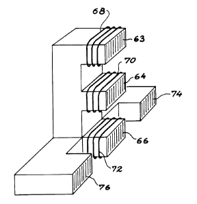
12 shows a device having three lateral branches 63,64,66
on which are wound receiving coils 68,70 and a transmitting
coil 72.
B 11781.3/PM
2~~'~~'~~
- 14 -
On either side of the branch 66 carrying the transmitting
coil there are two branches 74,76 not carryng coils and e.g.
made from the same material as the rest of the device. These
supplementary branches 74,76 have also an effect of channell-
ing the flue to the areas of interest. They also permit
a better decoupling with respect to other sensors located
in the borehole.
The two solutions described hereinbefore for channelling
the fluz of a transmitting coil can also be combined.
The invention described is applicable to conductivity and
susceptibility logging in geological deposits traversed by
boreholes. It can more generally apply to the measurement
of the electromagnetic characteristics of electrically condu-
ctive materials, e.g. by measuring their conductivity and/or
susceptibility.
B 11781.3/PM