Note: Descriptions are shown in the official language in which they were submitted.
WO 93/25892 ''~ ~ ~ ~ PCT/GB93/01216
- 1 -
Sensor for Optical Assay
This invention relates to a device for use in the
assay of chemical or biochemical entities, and in
particular to a biosensor for the detection of enzymes
or enzyme substrates.
Enzyme-based sensors (enzyme electrodes) have
previously been produced for the detection of a wide
variety of analytes, one instance being sensors for the
measurement of blood-gas concentrations (Clarke and
Lyons, Annals of the New York Academy of Science,
Vo1.102, pp 29-45, 1962). Many such biosensors employ
an enzyme whose catalytic reaction results in a pH
change which is recorded using either amperometric or
potentiometric electrodes. The concentration of the
analyte of interest is monitored by studying the rate of
change or the absolute change in pH. To improve both
the analytical performance and operational stability of
such devices, the enzyme is frequently immobilised
behind a semi-permeable membrane at the surface of the
pH electrode. Analytes studied in this way include
penicillin (Guilbault, G.G, Handbook of Immobilised
Enzymes, Marcel Dekker, New York, 1984) and glucose
(Clarke and Lyons, 1962). Advances in the field of
microelectronics led to attempts to miniaturise these pH
based enzyme sensor electrodes, substituting the .
conventional macro-pH electrode with a very much smaller
pH sensitive ion selective field effect transistor
(ISFET). Sensors for penicillin and glucose have been
fabricated using such technology and are reviewed in the
literature (Biosensors: Fundamentals and Applications,
edited by A.P.F. Turner, I. Karube, G.S. Wilson, Oxford
Scientific Publications, 1987).
However, such potentiometric systems suffer from_a.
number of disadvantages; for example they are prone to
CA 02137655 2003-09-29
- 2 -
electrical noise and interference due to other ions
present in the sample. Attempts have therefore been
made to fabricate the equivalents of such devices for
use in optical technology.
A sensor for penicillin has been reported (Kulp
T.J. et al, Analytical chemistry, Vol. 59, pp 2849-2853
1987) which employs an optical fibre, the end of which
is coated with a polymer into which is incorporated or
to which is bound a penicillinase and a pH-dependent
fluorescent dye. As the enzyme reacts with its
substrate, the change in optical properties of the dye
is measured and this change gives a measurement of the
substrate concentration. Such a device, however,
suffers from a number of disadvantages, in particular a
difficulty associated with its fabrication which
requires the immobilisation of a substantial mass of
enzyme and dye on the end of the fibre to achieve a
sufficiently sensitive assay. In use, difficulties
also arise from optical interference from the sample,
for example due to sample fluorescence and turbidity.
The present invention provides an enzyme-based
optical biosensor which overcomes many of the
disadvantages of the potentiometric pH sensors and the
optical fibre sensor described above.
According to one aspect of the present invention
there is provided a sensor device for use in assaying
for a substance selected from (i) enzymes capable of
producing a change in their environment as a result of
catalytic reaction with a substrate and (ii) substrates
for such enzymes, which sensor device possesses a
cavity or cavities each having a dimension small enough
to enable sample liquid to be drawn into the cavity by
capillary action, wherein a surface of the cavity has
CA 02137655 2003-11-27
- 3 -
immobilised directly or indirectly on a discrete region
of one longitudinal surface thereof a fluorophore
species whose optical properties change as a result of
the aforementioned change in its environment together
with a member of an enzyme suhstrate/enzyme pair
complementary to the substance under assay, and wherein
said surface is a surface of a transparent solid plate
which in use acts as a light-transmissive waveguide and
which forms a wall of the cavity, and wherein the
waveguide additionally has immobilised on at least one
discrete region of said longitudinal surface, distinct
from the measurement region, further reagents suitable
for a particular assay being performed, these further
reagents being chosen such that in use, said reagents,
together with optional ancillary reagents introduced
into the sample during operation of an assay and
together with an analyte under assay, when present,
give rise in said calibration regions) to either i) a
i
catalytic reaction analogous to that in the measurement
region, or ii) no catalytic reaction, or iii) a
catalytic reaction which results in no detectable
change in optical properties of any species present in
said region.
In the case of an enzyme for which a cofactor is
necessary for said catalytic reaction to occur, the
cofactor can also be present in the device or the
cofactor can be supplied separately.
According to a further aspect of the present
invention there is provided a method of assay for an
enzyme or an enzyme-substrate in a sample which method
includes the steps of:
CA 02137655 2003-11-27
- 3a -
(a) incubating the sample in the presence of a device
according to the invention as hereinbefore
defined;
(b) irradiating the device;
(c) monitoring an appropriate optical property ("the
measurement signal") thereby exhibited by the
species in said measurement region of said device:
(d) determining whether and, if desired, the extent to
which and/or the rate at which the said optical
property is altered by any change in the
environment in said measurement region; and
(e) using an appropriate algorithm, determining any
corresponding change in the environment in said
measurement region caused by any interaction of
enzyme and enzyme-substrate and thereby deriving a
measure of the concentration of the analyte under
assay.
The invention also relates to a kit for performing
a method of assay as defined above comprising a device
as defined above together with ancillary agents.
Where a cofactor is necessary for said catalytic
reaction to occur, if the cofactor is not already
present in or on the device, then it should be
introduced into the sample prior to, during or
subsequent to the incubation in step (a) above.
A wide variety of sensors according to the present
invention may be envisaged including, for example,
dipstick or 'test-strip' biosensors, devices using a
'sample flow-through' configuration or devices
employing sample containment, for example capillary
fill devices of the type generally described in
EP 171198.
CA 02137655 2003-11-27
- 3b -
Any enzyme which produces a change in its
environment as a result of its catalytic activity is
suitable for use in the device. Of particular note are
WO 93/25892 ~,~ . PCT/GB93/01216
- 4 -
enzymes which produce a pH change as a result of their
catalytic activity, for example, penicillinase, glucose
oxidase or urease. Many other changes are possible and,
include a change (increase or decrease) in the oxygen
concentration in the solution concerned, for example
using glucose oxidase which consumes oxygen as a result ,
of its catalytic activity, or the use of a peroxidase
which produces hydrogen peroxide as a result of its
catalytic activity.
The species whose optical properties change as a
result of a change in its environment may, for example,
be a fluorophore or dye sensitive to the change
concerned. Examples of preferred pH-sensitive species
include fluorescein isothiocynate (FITC),
fluoresceinamine and fluorescein iodoacetamide. A
preferred species sensitive to the oxygen concentration
in its environment is FITC. Several fluorescent species .
are sensitive to the HZOZ concentration in their
environment.
Devices according to the invention find particular
use in assays in which detection of the change in
optical properties of a fluorophore or dye is effected
by means of techniques involving the phenomenon of
evanescent wave coupling. Such techniques are well-
known and are, for example, described in US 4810658.
The use of such techniques enables the signal arising
from fluorophores located very close to the surface of a
waveguide to be distinguished from the signal arising
from fluorophores contained within the bulk of the
sample under assay thereby eliminating problems arising
from optical interference from the sample.
The irradiation of the device must be such as to
cause the immobilised species to exhibit'-its optical '
property e.g. fluorescence. The precise way of carrying
out the irradiation will, however, depend upon the '
nature of the device. For a capillary fill type device,
for example,.the technique will generally involve .
WO 93/25892 , ~ ~ ~ ~ ~ PCT/GB93/01216
irradiation of the measurement region of the waveguide
at an angle at or near to 90° to the longitudinal 'axis
of the waveguide, thereby exciting the species in that
region. For a fibre-type waveguide, for example, the
irradiation technique will generally involve propagation
longitudinally in the fibre and subsequent excitation of
the species in the measurement region. Such techniques
and consideration of their applicability to the
different types of devices available are well known to
the person skilled in the art.
The optical property of the species measured may
be, for example, the wavelength, intensity or
polarisation of the fluorescent light emitted.
Preferred devices and methods according to the
present invention are those in which the change in
environment occurring as a result of the enzyme
catalytic activity is a pH-change. The subsequent
description is set out in terms of devices and methods
of assay in which a pH-change occurs but the invention
is not to be considered as being limited to such a change.
The device according to the invention will now be
more particularly described with reference to
embodiments of the invention wherein the immobilised
species is a pH-sensitive fluorophore and the analyte
under assay is an enzyme-substrate (and hence the device
according to the invention has an enzyme immobilised
thereon).
In a device according to such an embodiment, the
fluorophore and the enzyme may be directly or indirectly
immobilised onto the surface of the waveguide in a
number of ways. When directly immobilised, these
components may either be immobilised separately onto the
waveguide, or the fluorophore can be conjugated to the
enzyme and the resulting conjugate may be immobilised
onto the waveguide. Fluorophores may for example be
immobilised by conventional coupling techniques.
Enzymes and enzyme/fluorophore conjugates may be
J
WO 93/25892 ~ ~~ ~ ~~ PCT/GB93/01216
- 6 -
immobilised by conventional covalent coupling techniques
or by suitable adsorption coupling techniques well-known
to those skilled in the art,., Indirect immobilisation
may be achieved by the use of an intervening species
bound to the waveguide, to which species the enzyme,
fluorophore or enzyme/fluorophore conjugate is
subsequently bound e.g. an antibody against the enzyme
or avidin bound to the waveguide immobilising
biotinylated enzyme.
A further example of an indirect immobilisation
technique involves the use of a membrane permeable to
the analyte under assay in which may be contained either
enzyme and/or fluorophore or enzyme/fluorophore
. conjugate, the species not contained therein being
immobilised to the waveguide as indicated above.
Alternatively the membrane may not contain any such
species but may simply be laid over those species
immobilised to the waveguide. In either case, the
function of the membrane is to protect the enzyme from
degradation by contaminants within the sample and also
to minimise the effect of the buffering ability of the
sample which would reduce the pH change caused by the
catalytic activity of the enzyme.
As mentioned previously, for enzymes requiring a .
cofactor in order to bind their substrate and/or
catalyse its breakdown into product, this cofactor can
be initially present in or on the device in an
appropriate amount in the vicinity of the measurement
region. Alternatively the required amount of cofactor
can be added to the sample prior to incubation of the
sample with the device or can be introduced into the
sample once incubation has begun. Where cofactor is
initially present this may be achieved, for example, by
containing it within the membrane referred to above.
Alternatively it may, for example, be contained within a '
dissoluble layer of a suitable material in the - .
measurement region either with or without the membrane
"",,WO 93/25892 PCT/GB93/01216
_ 7 _
referred to above being present. For a capillary-fill
device of the type generally described in EP 171148, the
cofactor may advantageously be contained in soluble
releasable form within a zone on the measurement region
(on one of the plates defining the region of sample
containment) or alternatively within corresponding zone
on the other plate such that on incubating the sample
the cofactor is introduced into the vicinity of the
measurement region.
The waveguide may be fabricated from a variety of
materials, the only criterion regarding their selection
being that they should be transparent to the wavelengths
of light employed in the irradiation of the sensor and
the wavelengths of the resulting propagated light from
the surface of the waveguide. Suitable materials
include glass, quartz and polymeric materials (such as
polyacrylate).
The change in optical properties of the fluorophore
may be measured by conventional methods for example, as
described in US 4810658 and in Badley et al,
Philosophical Transactions of the Royal Society of
London, Ser.B, Vo1.316, pp 143-160, 1987.
As mentioned hereinbefore a wide variety of devices
according to the invention may be envisaged. As
described in International Patent Application No.
PCT/GB91/02.058 it is possible to contain within a sensor
device, in addition to the measurement region, a number
of distinct regions for the purposes of internal
calibration. Such a principle can be applied to the
sensor device according to the present invention.
Hence, according to one embodiment of the device
according to the invention, the waveguide additionally
has immobilised directly or indirectly on-one or
optionally more than one discrete region of said
longitudinal surface, distinct from the measurement
region, ("the calibration regions)") further reagents
suitable.for the particular assay being performed,~these
WO 93/25892 ~ ~, ~~ ~,~ PCT/GB93/01216
_ g _
further reagents being chosen such that in use, said
reagents, together with optional ancillary reagents
introduced into the sample during operation of assay and
together with the analyte under assay, when present, ,
give rise in said calibration regions) to either i) a
catalytic reaction analogous and preferably of enhanced
or reduced extent to that in the measurement region, or
ii) no catalytic reaction, or iii) a catalytic reaction
which results in no detectable change in optical
properties of any species present in said region.
Thus, according to an embodiment of the method of
assay hereinbefore defined, the sample is incubated in
the presence of a device according to the invention
containing one or more calibration regions as
hereinbefore defined; additionally including the step of
monitoring an appropriate optical property ("the
calibration signals)") thereby exhibited by the species
in said calibration regions) of said device and from
the measurement signal and said calibration signal(s),
using an appropriate algorithm, deriving a measure of
the concentration of the analyte under assay.
Hence, in cases ii) or iii) in the embodiment of
the device described above, the calibration region will
correspond to a 'zero signal calibration region', using
the terminology of International Patent Application No.
PCT/GB91/02058. In case i) above where in the
calibration region a reaction occurs analogous but of
enhanced extent to that in the measurement, region, the
calibration region will correspond to a 'positive
calibration region' using the terminology of
International Patent Application No. PCT/GB91-02058. In
case i) above where in the calibration region a reaction
a
occurs analogous but of reduced extent to that in the
measurement region, the calibration region will
therefore, using similar terminology, correspond to a
. . . . ' negative calibration :region'..
According to a further aspect. of the present
~WO 93/25892 ~ ~r ~ ~ ~ PCT/GB93/01216
- 9 -
invention there is provided apparatus suitable for use
in a method of assay as hereinbefore defined which
comprises a device as hereinbefore defined; a source of
radiation capable of being arranged such that, in use,
radiation enters the said device such that the
immobilised species whose optical properties change as a
result of a change in environment in the device are
excited; and means for monitoring the emerging
radiation.
Specific embodiments of the device according to the
.present invention will now be described with reference
to the accompanying drawings.
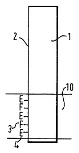
Figure la illustrates schematically an embodiment
of the device wherein the sensor is of the dipstick-
type. Onto a region 10 of one longitudinal surface 2 of
an optical waveguide 1 in the form of a glass sheet is
immobilised an enzyme (E) 4 and a pH-sensitive
fluorophore (F) 3.
Figure 1b illustrates the device of Figure 1a in
use. In use, the device is dipped into the sample 5
which, if it contains the analyte of interest, being the
substrate for the immobilised enzyme 4, the enzyme 4
will bind its substrate and catalyse its breakdown into
product. The catalytic reaction results in a change in
the pH in the local environment of the enzyme i.e. at
the surface of the waveguide. This change in pH results
in a change in the fluorescent properties of the
immobilised fluorophore 3. From a radiation source 13
light of the appropriate wavelength (selected by means
of suitable filters 14) to excite the fluorophore 3
falls onto the surface 6 of the waveguide and the
propagated light originating from~the end 7 of the
waveguide is detected evanescently. The-rate of change
or the absolute change in the wavelength, intensity or
polarisation of emitted fluorescence of the immobilised
fluorophore 3 is measured and the activity of the
immobilised enzyme 4 can thus be deduced.. From this,
WO 93/25892 ~ ~~~ PCT/GB93/01216
- l0 -
the concentration of the enzyme-substrate, the analyte
under assay, in the sample 5 can be determined.
Such a device may be calibrated by immersing it
into solutions containing a known concentration of the ,
analyte to be assayed. After~a suitable incubation
period, the fluorescence characteristics of the
waveguide are measured and a standard curve of the.
measured signal versus analyte concentration can be
constructed. The standard curve can then be employed to
relate the measured signal under operation of the device
to the concentration of the analyte under assay.
Figure 2a illustrates schematically an alternative
embodiment of the device wherein the sensor may be
employed to assay a flowing~sample. The sensor, as
described in Figure 2a, forms part of the internal
surface of a hollow structure having a cross-sectional
shape suitable for the application of the assay, but
preferably the portion 8 of the internal surface is
substantially cylindrical. Onto a region 10 of one
longitudinal surface 2 of an optical waveguide 1 is
immobilised an enzyme (E) 4 and a pH-sensitive
fluorophore (F) 3.
The mode of,operation of this embodiment of the
device is essentially as described for the device shown
in Figure 1b. Figure 2b illustrates the device of
Figure 2a in use. The advantage of this embodiment over
the device of Figure 1b is that it allows for the
continuous monitoring of a flowing sample stream 9, in
the path of which stream the device is placed. The
sample stream may be periodically interrupted to allow
for re-calibration of the device. This embodiment may
advantageously be used in conjunction with other
analytical techniques such as~flow injection analysis '
and high performance liquid chromatography.
Figure 3a illustrates schematically an alternative
embodiment of the device wherein the sensor is a
fluorescent capillary fill device (FCFD) of the type
",WO 93/25892
,~',~' ~ ~ PC'f/GB93/01216
- 11 -
more generally described in EP 171148. Such a device
comprises two flat plates separated by a capillary gap.
The sensor consists of a lower optical waveguide 1 in
the form of a glass sheet, onto a portion 10 of the
longitudinal surface 2 of which is immobilised an enzyme
4 and a pH-sensitive fluorophore 3.
Figure 3b illustrates the. device of Figure 3a. in
use. The sample 5 is introduced into the device or
enters the device by capillarity. The mode of operation
of the device is as described for the device illustrated
in Figure lb.
. Figure 4a illustrates schematically an embodiment
of the device in which a device in other respects
similar to that of Figure la additionally contains a
calibration region 11 onto a portion of which is
immobilised an enzyme (E) 4 and a pH-sensitive
fluorophore (F) 3, the calibration region also carrying
a layer comprising, in soluble releasable form, an
amount of the enzyme-substrate (S) 15. In use, any
reaction occurring in the measurement region 10 due to
sample analyte presence will be analogous to that in the
device of Figure la. The reaction occurring in the
calibration region 11 will be identical to that in
region 10 but, due to the presence of additional enzyme
substrate, will be of enhanced extent. Thus this region
11 will correspond to a positive calibration region.
Figure 4b illustrates an alternative calibration
region 11 which, in addition to having immobilised
enzyme (E) and pH-sensitive fluorophore (F), thereon,
carries a layer comprising, in soluble releasable form,
an amount of an enzyme inhibitor (I) 16 specific to the
enzyme E. Thus, in use, any reaction occurring in
region 11 due to sample analyte presence'will be of
reduced extent as compared with that in the measurement
region 10. Thus this region will correspond to a
negative calibration region.
Figure 4c illustrates schematically an embodiment
WO 93/25892 ~~~~~ PCT/GB93/01216
12
of the device wherein the device of Figure 1a
additionally contains two calibration regions 11 and 12.
Calibration region 11 contains those reagents described
for the positive calibration region above. Onto a
portion of calibration region 12 is immobilised
inactivated enzyme (E') 17 (i.e. enzyme inactivated in ,
the sense that it no longer binds to its substrate) and
a pH-sensitive fluorophore (F) 3. Hence in use, no~
binding of enzyme 17 to its substrate occurs and
therefore no catalytic reaction will occur in region 12.
This region will therefore in use correspond to a zero
signal calibration region. If instead enzyme 17 is
inactivated in the sense that it binds to its substrate
but does not catalyse its breakdown into product, in use
this region will correspond to a negative calibration
region. In the case of an enzyme requiring a cofactor,
absence of the cofactor will give an analogous result to
one or other of these possibilities.
Figure 4d illustrates an alternative calibration
region 12, onto which is immobilised a pH-sensitive
fluorophore 3 alone i.e. no enzyme is present. This
region in use will correspond to a zero signal
calibration region.
Figure 4e illustrates an alternative calibration
region 12, onto which is immobilised an enzyme non-
specific for the sample analyte (E ") 18 and a pH-
sensitive fluorophore (F) 3. This region in use will
also correspond to a zero calibration region.
Figure 4f illustrates an alternative calibration
region 12, onto which is immobilised an enzyme (E) 4 and
a non-pH sensitive fluorophore (F') 19. This region in
use will also correspond to a zero signal calibration .
region.
Further embodiments of the device wherein the
sensor is of the dipstick-type may be envisaged in which
w alternative combinations of the calibration regions 11
and 12 illustrated above are employed, or in. which more
CA 02137655 2003-09-29
- 13 -
than two calibration regions, selected from those
illustrated above for regions 11 and 12, are employed.
Similarly, embodiments of the device wherein the
devices of Figures 2a and 3a contain analogous additional
calibration regions may be envisaged. Figures 5a and 5b
illustrate two such embodiments.
Figure 6 illustrates an embodiment of the device
wherein the sensor is a fluorescent capillary device
containing in addition to the measurement region 10 two
calibration regions 11 and 12, onto each of which is
immobilised an enzyme (E) 4 and a pH-sensitive fluorophore
(F) 3. On a region 20 of the top plate 21 of the device is
carried a layer of enzyme substrate (S) 15 in soluble
releasable form. On a region 22 of the top plate 21 of the
device is carried a layer of enzyme inhibitor (I) 16 in
soluble releasable form. In use, when sample enters the
cavity within the device, reagents 15 and 16 dissolve and
diffuse towards regions 11 and 12 respectively. Hence in
region 11 an enhanced reaction occurs compared to that in
region 10 and in region 12 a reduced reaction occurs
compared to that in region 10. Region 11 in use is thus a
positive calibration region and region 12 in use is thus a
negative calibration region.
The following non-limiting Example serves to further
illustrate the present invention.
EXAMPLE 1 (Optical glucose sensor)
1.1 Pre aration of fluorophore- and enzyme-coated
waveguides
A sheet of Permabloc glass (Pilkington Glass Ltd., St.
Helens, UK) having a thickness of about 1 mm was cleaned
with detergent (e. g. Tween 20TM) in ultra-pure water with
ultrasonic agitation. The surface of the glass was
activated by incubating it in a 2o solution of
WO 93/25892 , PCT/GB93/01216 ~ .
14
t a H of 3 to 4
~aminopropyltriethoxysilane m water a p
for two hours at 75°C. After rinsing in water, the
glass sheet was dried at 115°C for at least four hours.
The glass was then incubated for 60 minutes in a 2.5% ,
solution of glutaraldehyde in a 0.05M phosphate buffer
(pH 7), and then washed thoroughly with distilled water.
The glass was incubated for two to four hours in a.l%
solution of a glucose oxidase (EC 1.1.3.4) in phosphate
buffer (pH 7). The glass sheet was then washed with
buffer solution. Unwanted adsorbed protein was removed
by soaking with a 6M urea solution in known manner. The
glass sheet was then incubated with a 1% solution of
FITC, followed by a wash step. This formed plate 1 of
the FCFD test device as illustrated in Figures 3a and 3b.
1.2 Fabrication of FCFD test devices
Test devices such as have been described in EP-A-0171148
were fabricated by screen printing onto the waveguide
resulting from step 1.1 above bonding tracks of an
ultraviolet curing glue (UVS 91, Norland Inc., USA)
containing glass microspheres of diameter 100~,m diameter
(Jencons Ltd., UK). A sheet of Permabloc glass onto
which had been screen printed opaque lids as described
in W090/14590 was then placed over the waveguide, and a
vacuum applied to the laminate. As result of the
vacuum, the upper sheet of glass was caused to press
down onto the glue, the glass microspheres defining a
gap of 100~m between the glass sheets. The laminate was
then exposed to an ultraviolet light source to cure the
glue. Finally, the laminate sheet was broken into
individual test devices as described in EP-A-0171148.
1.3 A aratus Used in the Measurement of the Glucose
Assa
Figure 7 shows a simple fluorimetry~apparatus which was
used to make suitable assay measurements as described in
_n
O 93/25892 ~ ~ 2 i 3 7 ~ 5 5 pCT/GB93/01216
GB8911462.3. Light from a xenon flash lamp 51
(Heinmann) is roughly collimated by a lens 52 before
passing through a filter stack 53 which defines the
wavelength range used to excite the FITC. The filter
stack comprises three filters:
a BG7 Schott glass filter (Ealing Electro Optics UK
Ltd., Watford, UK), a 450-480 nm FITC bandpass
interference filter (Optometrics Ltd., UK), a 474 nm
shortpass interference filter (Comar Instruments Ltd.,
Cambridge, UK).
A second lens 54 focuses the excitation light onto the
actie surface of the FCFD 56 through an aperture 55.
Light emitted from the optical edge 63 of the FCFD
passes through an aperture 57 which prevents light
emitted directly out of the solution contained within
the FCFD 56 entering the detection optics.
A lens system 58 collects the emitted light and an
aperture 59 defines the angular range over which the
emission i~ measured. This was chosen to coincide with
angles associated with evanescently coupled fluorescence
emission. A Schott OG515 515 nm colloidal glass
longpass filter 60 (Ealing Electro Optics UK Ltd.,
Watford, UK) filters out any scattered pump light and a
second lens focuses the emission onto a photomultiplier
detector (Hamamatsu R931A, Hakuto UK Ltd).
1.4 Assay procedure for glucose
Buffer solutions (0.05M phosphate, pH 7) containing
various concentrations of glucose were prepared. Either
buffer solutions containing no glucose or buffer
solutions containing glucose were added to the FCFD and
the change of signal arising from the device. was
monitored with time. As the immobilised enzyme
catalysed the breakdown of glucose the pH within the
device altered, changing the activity of the immobilised
w ~ FITC. figure 8 shows. the change in signal arising from
the FITC with increasing concentrations of glucose
within the device.