Language selection

Search

Patent 2137769 Summary

Third-party information liability

Some of the information on this Web page has been provided by external sources. The Government of Canada is not responsible for the accuracy, reliability or currency of the information supplied by external sources. Users wishing to rely upon this information should consult directly with the source of the information. Content provided by external sources is not subject to official languages, privacy and accessibility requirements.

Claims and Abstract availability

Any discrepancies in the text and image of the Claims and Abstract are due to differing posting times. Text of the Claims and Abstract are posted:

  • At the time the application is open to public inspection;
  • At the time of issue of the patent (grant).
(12) Patent Application: (11) CA 2137769
(54) English Title: CATAMENIAL APPLIANCE
(54) French Title: APPAREIL CATAMENIAL
Status: Dead
Bibliographic Data
Abstracts

English Abstract


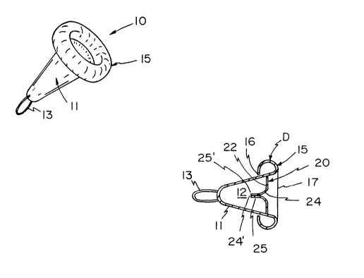
The catamenial appliance defines a menstrual flow
collection plenum and features a uni-directional menstrual
flow valve structure which when the appliance is in
engagement with the cervix, preferably overcovering the
fornix, permits menstrual flow into the plenum defined by the
appliance whereby the menstrual flow is collected, but when
the appliance is removed from the vagina as by pulling the
appliance downstream end, the valve structure seals off the
menstrual flow entry port confining the collected flow within
the plenum.


Claims

Note: Claims are shown in the official language in which they were submitted.


The embodiments of the invention for which an exclusive
property or privilege is claimed are defined as follows:

1. A catamenial appliance comprising:
(a) a flexible ring insertable into the vagina of a
female and adapted to surround the fornix of said female,
said flexible ring means being biased to expand slightly to
surround the fornix and to be juxtaposed thereagainst;
(b) a collection member integrally attached to said
flexible ring; and,
(c) a uniflow valve integral with the flexible ring
means and collection sheath defining an aperture of smaller
cross-sectional area than that defined by the flexible ring
so as to form a collection plenum with the collection member
and whereby menstrual flow passes through the uniflow valve
into the collection member;
(i) whereby menstrual flow collected within the
reservoir may be removed integrally with the
catamenial appliance without the menstrual flow
flowing out of the uniflow valve.

2. The catamenial appliance as claimed in claim 1, wherein
the uniflow valve consists of a membrane defining a flat
valve that depends into the plenum defined by the collection
member.

3. The catamenial appliance as claimed in claim 2, wherein
the flat valve has a substantially elongated neck portion
whose side walls mate to seal the aperture defined thereby
when menstrual flow is not passing into the plenum but
inhibits the flow of menstrual fluid in the opposite
direction.

4. The catamenial appliance as claimed in claim 1, wherein
the uniflow valve includes a flexible membrane on the inner
surface of the aperture so as to permit menstrual flow
through the aperture over the flexible membrane, for


collection of the same in the collection plenum.

5. The catamenial appliance as claimed in claim 1, 2 or 3
consisting of silicone.

6. The catamenial appliance as claimed in claim 4
consisting of silicone.

Description

Note: Descriptions are shown in the official language in which they were submitted.


` 2137769

CATAMENIAL APPLIANCE

This invention relates to an improved catamenial
appliance.
An improved catamenial appliance is made of resilient
elastomeric type of material which may be inserted into the
vagina so as to be in circumscribing ~uxtaposed and sealing
position about the fornix whereby it captively collects and
encapsulates within the body of the appliance the menstrual
flow while at the same time permitting the appliance removal
after filling by simply pulling at the downstream vaginal end
of the appliance so that it and contents are removed from the
vagina.
KNOWLES discloses a CATAMENIAL APPLIANCE in U.S. Patent
No. 4 799 929 issued 24 January 1989 which has a spring
biasing flexible ring insertable into the vagina and is
adapted to constrain about the cervix as separately attached
collection sheath. KNOWLES in U.S. Patent No. 4 955 875
issued 11 September 1990 further discloses as a
continuation-in-part and claims that the distal end of the
sheath of the appliance rests substantially in the vulvar
space of the female and acts as an interim collector that
features a "tap means" which allows the drainage out of the
collector so as to remove any menstrual flow from the
appliance prior to the appliance removal from the vagina.
The present invention avoids the disadvantages of the
bulk and uncomfortable tampon which is limited to absorption
capacity and provides a leak-proof appliance that may be
disposed within the vagina and preferably against the fornix
for collection there of all the menstrual flow which
normally is between l~oz and 2~oz of the menstrual fluid and
permits the removal of both collected menstrual flow and the
catamenial appliance in one single step after menstruation
has been completed. Additionally the invention when used
avoids the necessity that a tampon be fitted into the vagina.
Tampons absorb the menstrual flow flowing from the fornix
becomes saturated by the menstrual flow and cause sustained
contact of the menstrual flow against the vagina wall for
hours or sometimes even days. In some women constant

213776~


menstrual flow contact with the vagina wall causes infection.
The invention avoids the risk of infection from the sustained
contact of menstrual flow against the vagina walls.
It is a further ob~ect of the invention to provide a
catamenial appliance totally consumed by the vagina when
implanted therein but if desired may be used or positioned
within the vagina as to be partially consumed thereby
allowing the lower distal end of the catamenial appliance to
be exterior of the body.
It is a further ob~ect of the invention to provide a
catamenial appliance that requires only a sinale vaginal
insertion per menstrual cycle and hence avoid at least the
two vaginal insertions of the prior art of KNOWLES or the
plurality vaginal insertions when tampons are used.
It is a further ob~ect of the invention to provide a
single appliance which not only collects the menstrual flow
but allows the appliance to be removed and with it the
menstrual flow that it has collected hence voiding the
vagina of both menstrual flow and of the catamenial appliance
in a single removal sequence.
It is yet a further ob~ect of the invention to provide
a catamenial device which inhibits the passage of menstrual
flow out of the body. collects the menstrual flow within the
appliance when positioned in the vagina so that menstrual
flow can only flow into the appliance and that cannot flow by
the appliance and out of the body.
In this respect the catamenial appliance defines a
menstrual flow collection plenum and features a uni-
directional menstrual flow valve structure which when the
appliance is in engagement with the cervix preferably
overcovering the fornix permits menstrual flow into the
plenum defined by the appliance whereby the menstrual flow is
collected but when the appliance is removed from the vagina
as by pulling the appliance downstream end the valve
structure seals off the menstrual flow entry port confinina
the collected flow within the plenum. Once the appliance and
collected menstrual flow therein is exterior of the body it
may be disposed of by conventional means.

2137769


The invention therefore contemplates a catamenial
appliance comprising a flexible ring insertable into the
vagina of a female and adapted to surround the fornix of said
female said flexible ring means being biased to expand
slightly to surround the fornix and to be ~uxtaposed
thereagainst, a collection member integrally attached to said
flexible ring and a uniflow valve integral with the flexible
ring means and collection sheath defining an aperture of
smaller cross-sectional area than that defined by the
flexible ring so as to form a collection plenum with the
collection member and whereby menstrual flow passes through
the uniflow valve into the collection member whereby
menstrual flow collected within the reservoir may be removed
integrally with the catamenial appliance without the
menstrual flow flowing out of the uniflow valve.
Particularly the uniflow valve consists of a membrane
defining a flat valve that depends into the plenum defined by
the collection member. In the preferred embodiment the flat
valve has a substantially elongated neck portion wherein the
flat valve has a substantially elongated neck portion whose
side walls mate to seal the aperture defined thereby when
menstrual flow is not passing into the plenum but inhibits
the flow of menstrual fluid in the opposite direction. The
appliance is fabricated from a non-biologically active
elastomeric material such as silicone.
The invention will now be described by way of example
and reference to the accompanying drawings in which:
Figure 1 is a perspective view of the catamenial
appliance according to the invention,
Figure 2 is a side elevational view of Figure l;
Figure 3 is a top plan view of Figure l;
Figure 4 is a longitudinal cross section through
the appliance;
Figure 5 is a demonstrative figure for
descriptive purposes of how the appliance may be inserted
into the vagina,
Figure 5A through to and including 5D are
illustrative of the insertion sequence steps (but incorrectly

213776~


showing non-deformation of the appliance) while that of
Figure 5D is a perspective partially in section showing the
latter sequences of the insertion steps with the appliance
deformed (fingers causing the deformation not shown for
clarity) and being essentially that of sequence 5C and 5D;
Figure 6 is a perspective view showing the
appliance annular deformation when seated circumscribing the
neck of the cervix:
Figure 7 is an illustrative diagrammatical cross-
sectional view of the removal step;
Figure 8 is a perspective view of step 7 showingthe deformation of the appliance and the uniflow valve of the
appliance sealing the same closed constraining the menstrual
flow therein during the removal sequence of figure 7;
Figure 9 is a cross-sectional view, similar to
that of Figure 6 but of an alternative embodiment; and
Figure 9A is a cross-sectional view through the
uniflow valve of Figure 9;
Referring to Figure 1 the catamenial appliance
according to the invention is generally illustrated as~(10 ?
and consists generally of a conical sheath or member that at
its apex has a pull tab shown as a loop (13 ? but could be
in any other form like a protruding tag or the like. The
base of the conical sheath (11) extends at its base end
which is in fact the top end into an annular flexible
protrusion (15~ the inner margin of which is integral with
the conical sheath (11 ! . The annular protrusion and now
referring to the cross-sectional Figure 4 in fact is an
integral hollow annular piece but preferably has as its
distal annular margin (16) folded over and able to float
free; that is and comparing Figures 4 and 6 allows the
float-free distal annular tip (16) to migrate to and fro
depending upon as will become apparent hereafter the
lateral pressure provided against the annular flexible
protrusion (15) when positioned within the vagina at the neck
of the female fornix (30). This structure also assists in
sealing the catamenial appliance (10) closed on its removal
as will described hereafter with reference to Figure 6.

2137769


The uppermost plane of the annular flexible protrusion
(15) defines an opening (17) into the conical sheath. At a
point generally referenced (D) which is the largest
diametrical cross section referenced (D) in Figure 4 but on
the inside surface of the conical sheath there is extends
inwardly an annular flap valve generally referenced as (20)
consisting of an integrally molded radially inwardly
depending upper surface (22) defining an aperture (24) which
is preferably is a longitudinal aperture as seen in Figure
3 the inner margin of which extends inwardly into the plenum
(12) defined by the conical sheath so as to provide
longitudinal flat valves whose distal margin (25) are in near
~uxtaposition as more clearly seen in the cross-sectional
Figure 4 but provide a narrow longitudinal gap (24') at the
respective distal ends.
The appliance (10) is an integrally molded unit
structured from a biologically inert elastomeric material
such as silicone so that the annular flexible protrusion
(15) its distal end (16) the pull tab (13) and conical
sheath as well as the valve (20) are totally integrally~
molded from an inner elastomeric material such as silicone.
Referring to Figure 5 this shows that the deformation
arrow A can deform the outer surface of the annular
protrusion (15) and in fact collapse the body of the conical
sheath reducing the volume within the plenum as a preparatory
step for installation or fitting of the appliance into the
vagina.
Referring to Figures 5A through 5D these are cross-
sectional seauences of the insertion step showing
erroneously but for clarity the non-deformation of the
appliance (10). With thumb and index fingers positioned to
apply the force (A) as shown in Figure 5 on the flexible
annular protrusion (15) it can be moved to be inserted into
the vagina the arrow of Figure 5A and positioned so that
the apex protrudes out of the vagina shown in Figure 5B in
which case the flexible annular protrusion (15 ! extends
outwardly as shown in arrows of Figure 5B however
preferably the catamenial appliance should be inserted into

2137769


the source of the vagina that is at near or ~uxtaposed to
the fornix (30) it being shown in the almost seated position
in Figure 5C and in the seated position in Figure 5D. Figure
5E attempts to illustrate the deformation in perspective of
the catamenial appliance (10) during the whole sequence of
the insertion step shown in Figure 5 5E and in Figures 5A
through 5D.
Once in place and in sealing engagement or ~uxtaposed
about the fornix (30) and now referring to Figure 6 the
flexible annular protrusion (15) yields from the phantom
position shown into the solid position shown and this occurs
because of the constraint of the vagina on the outer
peripheral diameter of the flexible annular protrusion
slightly deforming the same into the solid position shown.
This is why it is preferred that the distal annular margin
(16) of the flexible annular protrusion is not mated to or
sealed to the exterior wall of the conical sheath but in fact
can migrate up and down so as to not provide to an airlock
within that plenum ~18) defined by the flexible annular
protrusion. During the menstruational period the menstrual
flow (40) follows in the direction of Figure 6 out of the
cervix into the uniflow valve (20) to rest on the orifice
(24) thereof and to slowly pass through between the opposite
lips (25) (25 25') into the plenum (12?. A volume of
approximately l~oz. to 2~oz. is only required because this is
the normal menstrual volume. The appliance (10) can
therefore be maintained in the cervical seated position of
Figure 6 until full voiding from the uterus of menstrual flow
occurs whereby all of it is collected as menstrual sediment
(42) within the plenum (12).
on the happening of the aforesaid events the
catamenial appliance (10) is removed and now referring to
Figure 7 by pulling on the loop or tag (13) with the thumb
or index finger some prefer the thumb and second finger in
the direction of Figure 7.
Now referring to Figure 8 during the removal step of
Figure 7 which should be conducted in one single continuous
motion the volume of the plenum (12 ? is partiallv collapsed

2137769


because the constant vaginal pressure not only on the
flexible annular protrusion (15?, but on the conical sheath
reducing the volumetric space within the plenum (12). This
is achieved by the folding out of the annular distal margin
(16 ? see Figure 8 causing mechanical biasing of the radial
valve surface (20) closing the distal margins (25) by urging
them against each other arrows in Figure 8 sealing closed
the flap valve aperture (24) during the physical withdrawal
of the appliance, further during this sequence and caused by
the menstrual residue (24) it pushes against the uniflow
valve (20) and particularly against the radial wall (22) and
the longitudinal flap fingers (25 25') with the longitudinal
slot (24). The area of the longitudinal slot at its outward
face at (24) is of greater area than at the interface (24')
hence during outward pulling of the catamenial appliance
(10) in the fashion shown in Figure 7 during the removal
step there is significant more pressure at longitudinal
orifice (24) which in fact collapses the same closed the
extent of the flaps (25) and (25') are long enough so that
the same does not reversibly flex and hence locks in the
menstruational residue (42) during the whole removal sequence
of the Figure 7 until the catamenial appliance (10) and the
residual menstrual sediment (42) has been totally voided of
the vagina.
Referring now to Figures 9 and 9A another embodiment
of the invention generally shows a catamenial appliance (10')
that has a uniflow valve (20') replacing the flat valve (25)
in the membrane (22). The flat valve (20') is anchored in
the membrane in a sealing fashion not clearly shown and
consists of a disk (40) defining a plurality of apertures
(41) in its forward face and on its obverse side an
integral annulus (43) and a central stem (44) which is
positioned on the axis of the disk (40) and annulus (43) and
carries a flexible annular flap (45) which in Figure 9A is
shown in the phantom position allowing menstrual flow (40)
into the catamenial appliance (10') as aforesaid.

Representative Drawing
A single figure which represents the drawing illustrating the invention.
Administrative Status

For a clearer understanding of the status of the application/patent presented on this page, the site Disclaimer , as well as the definitions for Patent , Administrative Status , Maintenance Fee  and Payment History  should be consulted.

Administrative Status

Title Date
Forecasted Issue Date Unavailable
(22) Filed 1994-11-30
Examination Requested 1995-03-06
(41) Open to Public Inspection 1996-05-31
Dead Application 1999-11-09

Abandonment History

Abandonment Date Reason Reinstatement Date
1998-11-09 R30(2) - Failure to Respond
1998-11-30 FAILURE TO PAY APPLICATION MAINTENANCE FEE

Payment History

Fee Type Anniversary Year Due Date Amount Paid Paid Date
Application Fee $0.00 1994-11-30
Maintenance Fee - Application - New Act 2 1996-12-02 $50.00 1996-11-25
Maintenance Fee - Application - New Act 3 1997-12-01 $50.00 1997-11-10
Owners on Record

Note: Records showing the ownership history in alphabetical order.

Current Owners on Record
HEIGHWAY, KIMBERLEY A.
Past Owners on Record
None
Past Owners that do not appear in the "Owners on Record" listing will appear in other documentation within the application.
Documents

To view selected files, please enter reCAPTCHA code :


To view images, click a link in the Document Description column. To download the documents, select one or more checkboxes in the first column and then click the "Download Selected in PDF format (Zip Archive)" or the "Download Selected as Single PDF" button.

List of published and non-published patent-specific documents on the CPD .

If you have any difficulty accessing content, you can call the Client Service Centre at 1-866-997-1936 or send them an e-mail at CIPO Client Service Centre.


Document
Description 
Date
(yyyy-mm-dd) 
Number of pages   Size of Image (KB) 
Claims 1996-05-31 2 48
Cover Page 1996-07-17 1 13
Description 1996-05-31 7 365
Abstract 1996-05-31 1 17
Drawings 1996-05-31 4 58
Representative Drawing 1997-12-11 1 7
PCT Correspondence 1998-02-16 1 33
PCT Correspondence 1998-02-16 1 25
PCT Correspondence 1998-03-30 1 35
Office Letter 1995-09-27 1 53
Office Letter 1995-12-11 1 26
Office Letter 1995-12-11 1 25
Examiner Requisition 1998-05-08 2 86
PCT Correspondence 1995-11-06 1 21
PCT Correspondence 1995-03-16 1 39
Fees 1997-11-10 1 32
Correspondence 1997-01-17 1 15
Fees 1996-10-25 1 39
Fees 1996-12-24 3 111