Note: Descriptions are shown in the official language in which they were submitted.
W094/02396 2 1 3 7 9 2 1 PCT/US93/06152
ARTICLE-HANDLING SYSTEM
Technical Field
The present invention relates to systems for
handling and operating on articles. More
particularly, the present invention relates to a
system using a fluid for holding, moving, detecting,
and operating on articles and for logic and control
elements.
Backqround of the Invention
Many commercially available devices use
gaseous and liquid fluids to inspect objects, sense
objects, transport material, clamp material, or
perform logic functions. Some examples are
dimensional air gauges, interruptable jet sensors, air
conveyors, machining vacuum chucks, venturi-suction
cup combinations, and fluidic logic modules. Many of
these devices are fabricated in rigid plastic and
metal configurations and are often attached to
products and equipment with fasteners, by we'~ing,
gluing, or with other rigid attachment methoàs.
Devices such as air tables and conveyors
which provide a cushion of air on which an article can
float are well known. However, while the article can
float on the air cushion or air bearing, additional
external devices or forces must be used to hold,
translate, rotate, detect, or otherwise operate on the
article.
Transport tables which use directional air
jets to transport articles also are known.
There is a need for a system which supports
and operates on an article which can act on an article
at orientations other than above a horizontal surface.
There is also a need to fabricate the above devices in
a layered configuration which can be quickly and
effectively attached to products and equipment.
W094/02396 2 1~ 7 9 2 1 PCT/US93/06152
SummarY of the Invention
The present invention is an apparatus for
handling and operating on an article. The apparatus
includes a member having a working surface and at
least one orifice which begins from an inlet, passes
through the member, and has at least one outlet on the
working surface. Fluid enters the member through the
inlet, passes through the orifice, and exits through
the outlet.
The member can be a web made of a plurality
of stacked layers which form a laminate. At least one
layer has one or more orifices. The orifices can be
oriented to cause the fluid exiting the orifices to
create a lower pressure than the ambient pressure
between the article and the working surface to cause
the article to be held on the working surface.
A fluid source is connected to the orifice
inlets. The fluid passing through the orifices
operates on an article on the working surface. This
operation could simply be holding the article in place
on the working surface. Alternatively, the operation
could include transporting the article along or
rotating the article on the working surface by
selectively directing and shaping the outlets of the
orifices. In other alternative embodiments, the
apparatus can serve as fluidic logic elements or as
inspection transducers, or can be used to sense the
presence of an article. Additionally, the apparatus
can be used to convert an existing surface into a
system for handling and operating on an article with
minimal increase in the thickness of the existing
surface.
Brief DescriPtion of the Drawinqs
Figure lA is a cross-sectional side view of
an apparatus for operating on an article according to
another embodiment of the present invention configured
W094/02396 ~2`1 3 7~9 2 1 PCT/US93/06152
-
to hold or transport an article.
Figure lB is a top view of the apparatus of
Figure lA.
Figure lC is an end cross-sectional view of
the apparatus of Figure 1.
Figure 2 is an end cross-sectional view of
an alternative embodiment of the apparatus of Figure
1.
Figure 3 is a schematic view of a
horizontal, one-dimensional, transport path.
Figure 4 is a schematic view of a downwardly
vertical transport path.
Figure 5 is a schematic view of an upwardly
vertical transport path.
Figure 6 is a schematic view of an
upside-down, horizontal, one-dimensional transport
path.
Figures 7A and 7B are cross-sectional views
of an apparatus for handling and operating on an
article according to another embodiment of the present
invention configured to transport an article in two
directions.
Figure 8 is a perspective view of a
transport track incorporating the apparatus of Figure
2S 1.
Figures 9, 10, and 11 are cross-sectional
views of tape winders incorporating the apparatus of
Figures 1 and 2.
Figure 12 is a partial cross-sectional view
of one embodiment of an apparatus for operating on an
article configured to rotate an article.
Figure 13 is a top view of the apparatus of
Figure 12.
Figure 14 is a schematic v of a curved,
3S two-dimensional transport path.
Figure 15 is a schematic view of a helical,
three-dimensional transport path.
W094/02396 ~ ~ PCT/~S93/06152
2137921
Figure 16 is a cross-sectional view of an
apparatus for operating on an article according to the
present invention configured to hold an article.
Figure 17 is a perspective view of a suction
cup incorporating the apparatus of Figure 16.
Figure 18 is a perspective view of a process
clamp incorporating the apparatus of Figure 16.
Figures l9A-19G are top views of layers used
to form the apparatus of the embodiment of Figure 16.
Figure 20 is a cross-sectional view of an
apparatus according to another embodiment of the
present invention configured to provide a pneumatic
switching article.
Figure 21 is a schematic view of a fluidic
logic element incorporating apparatus to provide a
logic and control function.
Figures 22 and 23 are cross-sectional views
of apparatus according to another embodiment of the
present invention configured to serve as inspection
transducers.
Figures 24 and 25 are cross-sectional views
of apparatus for handling and operating on an article
according to another embodiment of the present
invention configured to serve as article applicators.
Figures 26A, 26B, 27A, 27B, and 28 are
cross-sectional views of apparatus according to
embodiments of the present invention configured to
serve as article and proximity sensors.
Figure 29A is a perspective view of an
article sensor incorporating the apparatus of Figure
26.
Figure 29B is a perspective view of an
article sensor incorporating the apparatus of Figure
28.
Detailed Description of Preferred Embodiments
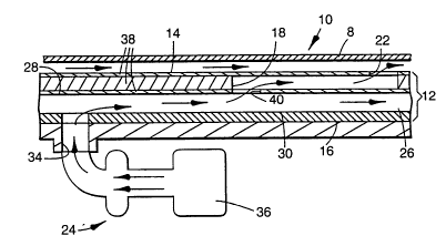
The system 10 handles and operates on an
W O 94/02396 2 13 7 9 2 1 PC~r/US93/06152
`, !~' L `
s
article 8 and can be easily adhered to an existing
surface. The system 10 can operate with various
working fluids although illustrated embodiments are
described as using air. As shown in Figures 1 and 2,
the system 10 includes a member 12, having a working
surface 14 and an opposing bottom surface 16. As
shown, the member 12 is flexible. At least one
orifice 18 begins from at least one inlet 34, passes
through the member 12, and has outlets 22 on the
working surface 14. Fluid, such as air, water, inert
fluorocarbons, and various other gases and gas
mixtures, enters the member 12 through the inlet 34,
passes through the orifice 18, and exits through the
outlets 22. In embodiments involving contact of the
article 8, such as shown in Figure 16 and described
below, the orifice 18 continues past the outlet 22 to
create suction.
The outlets 22 are the outlet for a conduit
assembly 24 which is in fluid communication with the
inlet 34 through the orifice 18. Fluid from each
outlet 22 exits the member 12 at a predetermined angle
and direction selected in combination with the desired
function of the system 10. Fluid exiting the outlets
22 flows between the working surface 14 and the
article 8 and the fluid flow direction from individual
outlets 22 can vary from the directional path of the
article 8.
The conduit assembly 24 includes a supply
manifold 26 which can be formed as part of the member
12, as shown in Figures 1 and 2, or mounted to the
bottom surface 16 of the member 12. In Figure lC, the
supply manifold 26 includes a channel defined by a top
wall 28, a bottom wall 30, and side walls 32. The
inlet 34 introduces fluid into the supply manifold 26
for distribution through the orifices 18 and outlets
22. A fluid source 36 is connected to the inlet 34.
The fluid source 36 can be a compressor which supplies
W094/02396 2 1 3~7 9 2 1 PCT/US93/06152
air under pressure to the conduit assembly 24. The
pressurized air exits through the outlets 22 in a
jet-like flow against the article 8. The alternative
embodiment of Figure 2 does not use the supply
manifold 26. Instead, a member 12 is mounted directly
to a pressure vessel or plenum chamber 37 with inlets
34 communicating with the orifices 18 and outlets 22
in the member 12.
The fluid passing through the orifices 18
handles and operates on an article 8 on the working
surface 14. The operation can be varied by changing
the system characteristics. Selecting the pattern,
direction, angle, shape, and length of the outlets 22
and the thickness of the layers 38 in combination with
the fluid pressure and the article properties
determines the operation. Particularly, the operation
can be altered by changing the angle a, shown in
Figure lB, at which the fluid exits the outlets 22.
The directional component 116 of the air flow
contributes to both the pressure differential and
transport of the article 8 while the cross-directional
component 112, perpendicular to the directional
component 116, contributes only to pressure
differential. The cross-directional component 112 and
the directional component 116 combine to yield the
flow direction 114. When the fluid exits with no
cross-directional component 112 the system 10
transports articles 8 with less pressure differential
than if there were a cross-directional component.
When the fluid exits with some cross-directional
component 112, the system 10 transports articles 8
with increased pressure differential. When the fluid
exits with no directional component 116, the system 10
holds articles 8 with no transport.
The jet-like air flow exiting the orifices
18 through the outlets 22 creates a controllable gap
between the working surface 14 of the member 12 and a
W O 94/02396 2 1 3 7 9 2 1 PC~r/US93/06152
bottom surface of the article 8. The gap is
established by balancing and maintaining equilibrium
among the forces, including gravity, on the article 8.
According to the Bernoulli principle, as the
air velocity increases, its pressure is reduced from
that of the surrounding fluid moving at a lower
velocity. The velocity difference causes a pressure
difference. An object placed between the high and low
velocity fluid will tend to be forced toward the
higher velocity fluid until equilibrium is reached.
Where a uniform fluid flow is forced between a
stationery working surface and a movable object, a
uniform force will be exerted on the object toward the
working surface. The object will not contact the
working surface if the object has an area-to-weight
ratio large enough so that the force from the air jets
exceeds the gravitational and other forces and the
product of the surface area of the article and the
pressure between the article and the working surface
must exceed the weight of the article.
As long as the fluid flow is uniform and the
article 8 has a sufficiently large area-to-weight
ratio, a uniform pressure is exerted on the article
toward the working surface. Minimum area-to-weight
ratios of 30 x 10 3 cm2/gm are preferred, although an
approximately 10 3 cm2/gm ratio is acceptable for
atmospheric applications. Therefore, the system 10
can operate when the member 12 and the article 8 are
horizontal with the article 8 on top of the working
surface 14 of the member 12 (Figure 3), as well as
vertical (Figures 4 and 5), with the article 8
underneath the working surface 14 of the member 12
(Figure 6), or at any orientation along the 360~ circle
of positions. The system 10 is orientation
independent.
The member 12 preferably is a web. At least
one layer 38 has one or more orifices. In a typical
W O 94/02396 ~s 2 1 3 7~ 9 2 I PC~r/US93/06152
embodiment, three layers 38 are used: a first layer
through which the fluid enters, a second layer which
establishes the direction of the fluid, and a third
layer through which the fluid exits. The layers 38
can be as thin as, for example, about 0.01 mm and can
be any flexible material. The layers 38 can be joined
or laminated by bonding, welding, or using adhesives.
Also, the layers 38 can simply be pressed together
without bonding. The layers 38 can be pre-laminated
with an adhesive on the outermost bottom layer and the
member 12 can be attached like adhesive tape to a
mounting surface which has ports to communicate with
those in the bottom of the member 12. A release
layer, such as silicone treated paper, may optionally
be included to facilitate storage and unwinding of the
article.
The layers 38 can be formed of plastics,
metals, ceramics, or composite materials. To prevent
static charge build-up on the working surface 14, the
working surface 14 can be metallic or conductive
plastic. Additionally, the transport fluid can be
ionized to facilitate the transport of materials that
might involve static charge build-up. The openings 40
in each layer 38 can be formed by any known method
including punching, drilling, or stamping. The
openings 40 can be perpendicular to or at acute angles
with the surface of the layer. Also, the orifices 18
formed when the layers 38 are stacked need not be
straight or linear and can have any desired shape.
Outlets with areas less than 0.0036 cm2 have been
fabricated. Air supplied at 4.25 x 10² m3/min (1.5
cfm) and 140 gr/cm2 (2.0 psi) to these outlets
transport articles at 760 cm/s.
As is shown in the Figures, the outlet can
create an angular, non-linear, stepped path for the
fluid. The outlet area can have any shape. It could
be rectangular, round, oval, or any regular or
~094/02396 ` 2 1 3 q 9 2 1 PCT/US93/06152
irregular polygon and need not be dictated by the
formula for commonly-drilled holes with a circular
cross section bit which, when drilling at an acute
angle with the plane of the working surface, form an
outlet at the working surface having an oval cross
section with a length to width ratio governed by the
drilling angle ~ as expressed in the equation l/w =
1/sin ~. Thus, the outlet 20 can extend through the
working surface 16 to deliver fluid to the working
surface at an effective angle of less than 20 with an
outlet having a length to width ratio less than 2.9.
The outlet length to width ratio is not limited by the
drilling angle formula and length to width ratios much
less than dictated by the formula can be achieved.
Thus, for example, the effective angle can be less
than 15 and the length to width ratio less than 3.8,
the effective angle can be less than 10 and the length
to width ratio less than 5.7, and the effective angle
can be less than 5 and the length to width ratio less
than 11.4.
In a modification shown in Figures 7A and
7B, a movable wiper lamination layer 42 can open and
close the orifices 18 to turn on and off the fluid
jets passing through the orifices. The wiper
lamination layer 42 also can reverse the direction of
fluid flow through the orifices 18. As the wiper
lamination layer 42 moves from the position in Figure
7A to that in Figure 7B, the fluid inlet is switched
to change the fluid jet direction.
The system 10 has numerous uses. The
operation includes moving or holding an article 8
without contacting the article as illustrated in
Figures 1, 2, and 8-13. The article is simply
transported without contact. The transport of high
area-to-weight ratio articles 8 is accomplished while
holding the article adjacent the working surface 14.
The system 10 can transport disks, such as shown in
W094/02396 2 1 37 9 2 1 PCT/US93/06152
Figure 8. Similarly, the system 10 can be used to
pick up an article 8, such as a disk, without
contacting the article, and transporting the article
to another location at which a separate system lo can
receive the article without contact. This
transportation can be accomplished either by using the
fluid streams of the system lO or, conventionally, by
physically moving the system 10 itself. The system 10
transports webs such as tapes, which are compliant and
have a high area-to-weight ratio, by threading and
winding the tape ends through a tape winding apparatus
or end product such as a cassette. The jet-like air
flow exiting the outlets 22 supports the article 8 and
has sufficient force to move the article 8 in the
direction of the ejected air. The article 8 is held
adjacent the member 12 regardless of the working
surface 14 orientation. Transport paths are two or
three-dimensional, as shown in Figures 14 and 15.
An acute angle b relative to the working
surface 14 as shown in Figure 12, which rotates an
article 8, is preferred. When used to transport
articles 8, minimizing this angle and the fluid flow
component perpendicular to the working surface 14
maximizes the component of fluid flow in the direction
of travel.
The system 10 has been used with tape
winders 78 and tape threaders 80, shown in Figures 9-
11. The tape 79 will not contact the member 12 around
bends due to the small outlet construction. For
example, as shown in Figure 9, the member 12 has been
used to thread movie film 81, supplied to the member
12 from a supply reel, through a projector's film
path. After threading, stopping the air flow through
the outlets 22 allows the film 81 to be used for
projection. Similar principles have been applied to
the use of the system 10 with data, video, and audio
magnetic and optical tapes 79. The member 12 has been
WO 94/02396 r . ~ PCI/US93/06152
- 2137921
11
used to thread new reels of tape 79 into winders 78,
as shown in Figure 10. The member 12 enables the tape
79 to be wound onto a reel without a leader. Also, as
shown in Figure 11, the system has been used with
single reel cartridges 84 to transport the tape 79 and
connect tne cartridge reel to the resident drive reel
with the member 12. Several members 12 can be used
together to transport wide tapes and webs. Gaps
between adjacent members 12 can serve as vent passages
for the transport fluid.
In another example embodiment, the transport
system is formed of a layered construction using three
layers. (All dimensions are approximate.) The first
layer 52 is 0.4 mm thick and is made of a vinyl
material with adhesive on one side to adhere to the
second layer. The second layer 56 is 0.4 mm thick and
also is made of a vinyl material. The second layer
can have adhesive on both sides to adhere to the first
and third layers. The third layer 60 is 0.1 mm thick
and is made of stainless steel. The working surface
16 formed on the third layer 60 is 25 mm wide. This
transport system has two arrays of orifices 19 and two
arrays of outlets 20 are formed in the working surface
16. The outlets 20 are rectangular and have a width
of 1.0 mm and length of 5.0 mm. The outlets are
oriented at an angle with respect to a the centerline
of the working surface of 30. The outermost portion
of the outlets 20 (from the centerline) is 3.5 mm
from the side edge of the working surface, 14.0 mm
from corresponding outlets on the other side of the
centerline, and 12.0 mm from the outermost portion of
the adjacent outlet on the same side of the
centerline. The outlet creates an angular, non-
linear, stepped path for the fluid. This path causes
fluid to exit the outlet at a 1 angle with the working
surface. This angle is defined, referring to Figure
2, as the angle formed between the diagonal line
W094/02396 ~ ~3 ~ 9 ~1 PCT/US93/06152
connecting the lower left and upper right corners of
the outlet 20 formed in the third layer 60 and the
working surface 16. (The third layer 60 is 0.1 mm
thick and the outlet length is 5 mm.)
A transport system 27 cm long formed in a
loop and having 45 outlets was used to transport a
flexible tape which was 25.4 cm long, 2.54 cm wide,
25.4 microns thick, and was 0.22 grams. The air mass
flow rate entering the inlet in the first layer ranged
from 0.0006 kg/sec to 0.0010 kg/sec (the air velocity
ranged from 27 m/sec to 235 m/sec with the directional
component ranging from 23 m/sec to 204 m/sec). This
produced an air velocity at the outlet of up to 300
m/sec transported the article at speeds of up to 1650
cm/sec.
The member 12 can provide high velocity
noncontact transport of die-cut flexible disks when
extracting the disk from presses after die-cutting.
Moreover, the air transport system removes loose
debris. Support of the disk adjacent the working
surface 14 allows the disk to be transferred from one
member 12 conveyer to another for changing containers
or article collection. By using both
forward-propelling and reverse-propelling outlets 22,
curl of the punched disk is reduced as a function of
the pressure differential.
A variation of transporting is rotating the
article 8 on the working surface 14. This is shown in
Figures 12 and 13. Articles such as magnetic or
optical disks with a conventional or non-conventional
form factor have been used. Credit card-shaped media
have been rotated and round media within credit card-
shaped jackets can be rotated. Additionally, the
system has been used as an air drive, with abrasive
films to provide light sanding or polishing heads.
Alternatively, in a contact/hold-down
embodiment, as shown in Figures 16-18, the system 10'
W094/02396 " 2 i 3 7 9 2 1 PCT/US93/06152
has been used to orientation independently hold an
article 8 in place on the working surface 14 while
contacting the article 8. In this embodiment, after
contact and establishing a vacuum, none of the fluid
passes through the outlets 22 on the working surface
14. The fluid passes through the orifices 18
initially and exits through additional passages which
serve as a vent 21. The combination of orifices 18
and vent 21 forms a complete path connected to the
fluid source 36 and the resulting suction holds the
article 8 against the working surface 14. The system
10' can be a suction cup 70, as shown in Figure 17,
used to handle paper and components, and in part
feeding applications. The suction cup has been
adhered to a support block 74 using an adhesive layer
72. The system 10' also has been used as a process
clamp 76, shown in Figure 18, to hold parts for
process operations. The member 12 lines the walls of
the process holding fixture. Also, a vacuum chuck
using the system 10' can hold non-magnetic materials
for milling, grinding, and engraving.
Figures l9A-19G illustrate the layers 38 of
the member 12 configured for contact holding using
vacuum as described with respect to Figures 16, 17,
and 18. This embodiment uses a venturi layer to
generate a partial vacuum. The first layer 44, shown
in Figure l9A, is the inlet layer and includes an
opening 46 which serves as the inlet 34. The second
layer 48, shown in Figure l9B, is a venturi layer and
includes an opening 50 which generates a partial
vacuum. Air enters the venturi layer 48 at 136,
passes through the nozzle portion 138 and gap 140, and
exhausts at vents 142 and 144. The flow exiting the
nozzle portion 138 reduces pressure in the gap 140.
This low pressure is distributed through the remaining
layers 52, 56, 60, 64 to the working surface layer 68.
The third and fourth layers 52, 56, shown in
W O 94/02396 ~ ~ L PC~r/US93/06152
Figures 19C and l9D, respectively, include elongate
openings 54, 58 which are generally oriented to
distribute the air in the direction of flow. The
fifth layer 60, shown in Figure l9E, includes elongate
openings 62 which direct the air to the outlets 22.
The sixth layer 64, shown in Figure l9F, includes
openings 66 which serve as the outlets 22 through
which the air exits the orifices 18 formed by the
openings 50, 54, 58, 62. The seventh layer 68, shown
in Figure l9G, is the porous, nonwoven working surface
layer and covers and protects the member 12 from
debris. The nonwoven web distributes the partial
vacuum uniformly across the working surface 14 and
permits fragile, highly polished, or cosmetic parts to
be held for transport during manufacturing processes
without damage. A plurality of independent laminate
constructions as previously described has been
assembled into an array of elements. Test partial
vacuums have exceeded about 4.8 x 10⁴ pascal. In
alternative embodiments, a vacuum source has been
coupled to the layers 52, 56, 60, 64 to attain similar
holding benefits.
In another operation of the system 10, the
orifices 18 can be oriented to serve as fluidic
switches 86, shown in Figure 20 or logic elements 88,
shown in Figure 21. The membrane switches can be made
with materials similar to those used in electronic
membrane switches such as PET and the like. The
switches can be used to pilot air valves or to provide
a logic and control function.
The system 10 also has served as inspection
transducers 90, as shown in Figures 22 and 23. In
Figure 22, the member 12 is used for dimensional air
gauging. When the distance from an article to an
outlet is less than one third of the diameter of the
outlet, the pressure measured in the outlet is
proportional to that distance. As the distance d
~094/02396 2 1 3 7 9 2 1 PCT/US93/06152
decreases, flow from the outlet decreases, resulting
in an increase in the pressure measured at m. In
Figure 23, the member 12 is used for gauging a surface
finish. The surface roughness of the material being
tested acts as a flow restrictor. A rough microfinish
creates turbulence, reduces the air flow and raises
the pressure measured at the outlet. A polished
surface promotes laminar flow with a resultant lower
outlet pressure. The measured outlet pressure
provides an analogue to the actual surface finish of
the sample being tested.
The system 10 also can be used, when
attached to the appropriate tooling, as a tape
applicator 92 to facilitate the application of tapes
to products having complex contours. This is shown in
Figure 24, which depicts decorative tape being applied
to a product 91. A length of tape can be cut from a
roll, fed into position by the member 12 attached to
an application pad 93, and applied to the product by
downward movement. In the loading position, the
member 12 and pad 93 are lowered to press the tape
against the product 91. Application begins at the
tape edge and continues across the tape surface until
the application is complete to prevent air entrapment.
When the tape has been applied, the air supply is
deactivated and the member 12 is raised. As the
member 12 does not physically contact the tape being
transported and applied, adhesive tapes can be
transported with the adhesive layer 72 facing the
- 30 member 12, as shown in Figure 25.
The operation also has been used to sense
the presence of an article 8, as illustra~ed in
Figures 26-29. Figure 26 shows a back pressure
article sensor 94. When air exits from the outlet 22
the resultant pressure measured at the control
interface near the outlet 22 is low. When an object
placed near the outlet impedes flow, the interface
W094/02396 2 1 3 7 9 2 1 PCT/US93/06152
pressure increases to signal the presence of the
object as shown in Figure 26B. Figure 27 operates on
an interruptable air flow principle. Two systems 10
are separated by a gap with the orifices 18 on each
member 12 oriented to permit fluid exiting the outlets
22 to contact and sense the presence of an article 8
between the systems. The pressure in the receiver
system 96 drops when the article 8 is between the
sender system 98 and the receiver system 96. In
Figure 28, the range of this interruptable air flow
system is increased by using a cross-fire technique.
A second sender system 100 ejects air into the stream
between the first sender system 102 and the receiver
system 96 and the sensing gap extends from the outlet
22 of the second sender system 100 to the sides of the
first sender and receiver systems 102, 96. The flow
from the second sender system 100 normally diffuses
the first sender air flow. When an article 8 is
present, the flow from the second sender system 100 is
interrupted, and the pressure at the receiver system
96 increases. Figure 29A is a perspective view of the
sensor 94 of Figure 26 and Figure 29B is a perspective
view of the sensor 95 of Figure 27. The sensor body
can be attached to an existing surface. A supply
manifold in the sensor body provides air flow and a
passage sends a pressure build-up signal to a control
system when an object is close to the sensing port.
The system 10 has been used to convert an
existing surface into a system for handling and
operating on an article 8 by adhering to the existing
surface. The converted surface with the system 10 has
a thickness that is only slightly thicker than the
unconverted surface. Thus, surfaces can be converted
inexpensively and quickly. Where the existing surface
to be converted is a fluid supply manifold, holes can
be formed in the surface of the manifold to
W094/02396 ? - ~ PCT/US93/06152
- 2137921
17
communicate with the orifices 18, as shown in Figure
2.
The method of handling and operating on an
article 8 includes the steps of placing the article 8
on the working surface 14 and passing fluid through
the orifices 18 to handle and operate on the article