Note: Descriptions are shown in the official language in which they were submitted.
WO 94/00749 PCT/GB93/01357
- 1 -
Lictht Measurement Ap~~aratus
This invention relates to light measurement
apparatus, in particular, though not exclusively, to
colour and/or intensity measurement apparatus for use
with for example a biomedical diagnostic test card.
In recent years there have been developed test
cards, e.g. solid phase immunoassay test cards, for
biomedical diagnostic purposes. Such test cards are
normally provided with one or more test sites, normally
only a few millimetres (eg. about 5 millimetres) wide,
to which a liquid sample (e.g. blood or serum) is
applied. The test sites are designed to change colour
in response to the presence and concentration of a
particular component (e.g. a certain protein) in the
liquid sample.
This colour change can, at least to a certain
extent, be detected and measured by eye, by for example
comparing a treated test site with a reference colour
chart. Such visual techniques are, however, clearly
unsatisfactory when it is desired to produce an accurate
reliable measurement. To obtain reliably highly
accurate measurements, an instrumental system is sought.
Measurement of colour, colour spectra and colour
intensity of an opaque surface is performed by analyzing
the light reflected from the surface when exposed to a
defined light. It is essential that the surface area to
be measured and the detection system are not exposed to
external light during measurements, and light shielding
of the mechanism is therefore provided. This is
particularly critical if weak light sources such as
' light emitting diodes (LEDs) are used rather than strong
sources such as xenon arc lamps or the like. It is also
important that the light emitter and the light detector
have defined positions relative to the surface to be
measured.
VVO 94/00749 PCT/GB93/01357
~1 _2_
Conventional instruments for analyzing surface
colours tend to be large and heavy, thus not readily
transportable, or smaller but still inflexible in use.
Attempts to develop more versatile, small transportable
systems have been made, but to date no known system
meets all the requirements to overcome the problems of
the prior art.
According to the present invention there is
provided light measurement apparatus comprising an
elongate member, said elongate member having at one end
thereof light-emitting means and light-detecting means,
at least the end of said elongate member provided with
said light-emitting means and said light-detecting means
being surrounded by a resiliently biassed sheath whereby
in use when said elongate member is applied to a surface
to take a reading said sheath defines a light-tight
enclosure.
Preferably, the light-emitting and light-detecting
means may comprise electronic components such as
photodiodes, phototransistors or the like whereby the
dimensions at the.end of the member (i.e. the "tip") may
be small so that the apparatus may be applied to a small
surface area. The provision of a sheath to define a
light-tight enclosure enables a low intensity light
source to be used as the light-emitting means, e.g. a
light-emitting diode (LED).
The light-emitting means may comprise means for
emitting broad spectrum light or light of limited
wavelength ranges. The use of two or more narrow band
emitters will allow simple spectral analysis to be
performed. Such a possibility is particularly
advantageous when it is desired to measure concentration
ratios) of two or more components on the test site
which absorb light of different wavelength
bands/regions. In this latter arrangement, two or more
separate light sources may be provided, e.g. two or more
LEDs, or alternatively switchable filter means may be
PCT/GB93/01357
WO 94/00749 ~,,
- 3 -
provided to a single light source. Since absorption
spectra from coloured surfaces always are of a broad-
band nature, the signal-to-noise (S/N) ratio can be
improved during measurements by using broad-band light
emitters which coincide with the absorption range.
The sheath is preferably adapted to be slidable
between the position in which it defines a light-tight
enclosure, and a position in which the end of the
elongate member is exposed. This facilitates initial
application of the apparatus to a small area, after
which the sheath may be moved to define the light-tight
enclosure. Preferably, indeed, the sheath may be
biased, e.g. by resilient means such as a spring, into a
position to expose the end of the elongate member. The
end of the sheath adjacent the end of the elongate
member may be provided with a sealing ring to further
ensure a light-tight seal.
The operation of the apparatus to effect a
measurement may simply be left for an operator's
command. Preferably, however, the tip of the elongate
member is provided with a light sensor (e.g. a
phototransistor or the like) to be located within the
light-tight enclosure. The light-sensor can be arranged
to detect when it is sufficiently dark within the
enclosure for a reliable accurate reading to be taken
and via control circuitry may then cause a measurement
to be taken.
In addition to defining a light-tight enclosure,
the provision of a sheath member also has the advantage
of helping to ensure that the apparatus is operated in
the correct orientation, i.e. perpendicular to the
surface to be measured.
It is also particularly preferred that the light-
emitting means and the light-detecting means are
arranged asymmetrically with respect to each other, to
avoid any problems with light being directly reflected
off a glossy surface. Indeed viewed from another aspect
CA 02138040 1999-11-OS
4
the invention provides light measurement apparatus comprising an
elongate member having at one end thereof light-emitting means
and light-detecting means, said light-emitting means and said
light-detecting means being asymmetrically arranged with respect
to the central axis of said elongate member.
An embodiment of the invention will now be described by way
of example and with reference to the accompanying drawings, in
which:-
Fig. 1 is a sectional side view of apparatus according to
an embodiment of the invention;
Fig. 2 is a cross-section through the apparatus in the
region of the tip thereof;
Fig. 3 is a view along line III-III; and
Fig. 4 is a view along line IV-IV.
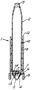
Referring first to Fig. 1 there is shown therein an
elongate pen-like member 1 comprising a cylindrical housing 2.
One end of the housing 2 is provided with an aperture for
receiving a cable 3 by means of which the light-emitting,
-detecting and -sensing elements (to be described below) may be
operatively connected to a remote control unit such as a
microprocessor (not shown). The apparatus may include light
intensity measurement circuitry of the type disclosed in
International Published Application W094/00742 published on
July 6, 1994.
The other end of the cylindrical housing 2 is closed by a
base member and conical tip member 4. The conical tip member 4
is formed with a hollow central chamber 5 within which are
located light-emitting means in the form of a light-emitting-
diode (LED)6, and light detecting means in the form of a
photodiode 7. The chamber 5 opens to the exterior of the tip
member 4 at the apex thereof which defines a measurement
location which is positioned on the central longitudinal axis of
the housing 2. Locating the LED 6 and photodiode 7
WO 94/00749 ~ 1 ~ ~ ~ ~ PCT/GB93/01357
z
- 5 -
recessed within the conical tip member 4 both helps
protect them from accidental damage and shields them
partly from stray light.
Surrounding the lower half of the housing 2 is a
cylindrical sheath 8 of light impermeable material,
around the lower end of which is provided an annular
sealing ring 9 formed for example of a resilient
elastomeric material. A spring 10 is located between an
annular shoulder 11 formed at a lower end of the housing
2 and an inwardly directed annular rim 12 formed at the
upper end of sheath 8. The spring 10 normally biases
the sheath 8 upwardly out of the position of Fig. 1 to
expose the conical tip member 4. In use, the tip member
4 is applied to the surface to be measured and
subsequently the sheath 8 is moved downwardly against
the spring bias until the sealing ring 9 contacts the
surface around the region to be measured. There is thus
defined a light-tight enclosure within which are
received the surface to be measured, and the light-
emitting and detecting means.
A bore 13 is formed in the conical member 4 and the
base of the housing 2 at the end of which remote from
the exterior is provided a photo-transistor 14. The
phototransistor 14 is adapted to sense when the light
within the light-tight enclosure is below a minimum
level for an accurate measurement to be taken. The
phototransistor 14 then sends a signal to the control
means to cause the LED 6 to operate to take a
measurement.
As can be seen from Figs. 2, 3 and 4, the LED 6 and
photodiode 7 are positioned asymmetrically with respect
to each other and the central longitudinal axis of the
housing whereby if the apparatus is applied to a glossy
surface, directly reflected light from the LED 6 cannot
be received by the photodiode 7.
Although the invention has been described with
particular reference to colour measurement, it will be
WO 94/00749 Q ~ PCT/GB93/01357
- 6 -
appreciated that the range of applications is wider and,
for example, with suitable programming of the control
means, the invention could be applied to a bar-code
reader, e.g. for up-dating the apparatus with new test
data.
It should also be understood that although
reference is made in this specification to the term
"light", it is not intended that the invention be
limited to visible light, but rather the invention may
also extend to the non-visible parts of the
electromagnetic spectrum.
In addition to solid phase immunoassay test cards,
the apparatus may of course also be used to measure
relative colour intensity in other analytical methods
giving rise to coloured responses, e.g. dot/spot
immunoassays and electrophoretic blotting systems.