Note: Descriptions are shown in the official language in which they were submitted.
~- 21~818'3
--1
94246A
h~l~O~ AND APPARATUS FOR VEHICLE TRIM
PANEL HA~ING HIDDEN AIR BAG DOOR
Background of the Invention
This invention pertains to the art of vehicle
instrument panels or other trim panels and more
particularly to a vehicle trim panel having an air bag
deployment system mounted therein and in which a door
through which the air bag is to be deployed is
invisible to vehicle occupants prior to such
deployment.
Related Art
~ Automotive vehicles have long utilized restraint
systems for the safety of vehicle passengers.
Initially, such restraint systems included seat belts
which fit over the occupant's lap. Later many
restraint systems were modified to add an additional
strap, or shoulder harness, which crossed the
occupant's chest and further protected them against
impacts. Of late, air bag supplemental restraint
systems have become increasingly popular. A typical
air bag supplemental restraint system includes an
inflatable bag which is stored in a deflated condition
within the vehicle steering wheel or trim assembly.
Upon a relatively severe impact, the air bag is
rapidly inflated and deployed into the passenger
compartment through various means and openings.
Early air bag deployment systems included a
requirement that the opening through which the air bag
would be deployed was weakened or somehow configured
to insure its successful deployment. Usually the
weakened areas were thin spots or cuts in the vehicle
interior trim components. The cuts were visible to
- 213~1~3
the vehicle occupants and they detracted from the
appearance of the vehicle interior. As such, a need
arose for an effective air bag deployment system which
was obscured or hidden from the view of vehicle
occupants until such deployment.
U.S. Pat. No. 5,072,967 to Batchelder et al.
discloses a cover assembly for an air bag restraint
which has a smooth cover. An outer cover member has
weakened sections on an inboard surface to facilitate
deployment of the air bag through the opening created
thereby. To reduce the probability of such weakened
sections being visible to vehicle occupants, a filler
material is placed between the weakened outer cover
member and an insert to prevent inward collapse of the
outer cover member at the weakened sections. In
addition, an insert of alllm;nllm is formed in the
filler material and, upon deployment of the air bag,
is stressed against the weakened sections of the cover
member to deploy the air bag. It is a more
complicated system than that of the invention.
U.S. Pat. No. 5,082,310 to Bauer discloses an
arrangement enclosure for an air bag deployment
opening to be formed in the interior trim structure of
an automotive vehicle. The closure includes a
substrate section which is weakened in a pattern to
form contiguous doors or subsections which split apart
along purportedly invisible seams when an air bag is
inflated. Upon such inflation, the resulting pressure
on the inside of the opening causes the preweakened
skin of the foam plastic layer to split apart along
the seams, allowing the air bag to be deployed into
the vehicle interior. This arrangement requires the
skin of the foam plastic layer to be weakened in a
matching pattern above the seams in the substrate
section. It is believed this embodiment is also more
~ ~1381~3
complicated than the present invention and requires
that the outer skin of the vehicle interior be
weakened over a substantial portion of its area for
proper deployment of the air bag.
The present invention contemplates a new and
improved vehicle trim panel for use with an air bag
deployment system which is simple in design and which
overcomes the foregoing difficulties in others while
providing better and more advantageous overall
results.
Summary of the Invention
A door and frame in a motor vehicle interior
instrument panel or other trim panel includes the
panel having an inner side adapted to at least
partially enclose an air bag supplemental restraint
system. The panel has an outer side having a trim
element designed to be viewed by a passenger in the
motor vehicle. The trim element overlaps door and
frame and obscures a joint between the door and frame
when the panel is installed in a motor vehicle. The
trim material is able to self-heal small punctures or
cuts within it. A foam material on the inner side of
the panel is prevented from passing through the
punctures or slits in the trim material due to its
self-healing characteristic. The frame is reinforced
by a reinforcing member to be relatively strong in
comparison to the door and deflecting much less than
the door when the door and frame are equally loaded.
Brief Description of the Drawings
The invention may take physical form in certain
parts and certain arrangement of parts, a preferred
embodiment of which will be described in detail in the
`- 2138183
specification and illustrated in the accompanying
drawings, which form a part hereof and wherein:
Figure 1 is a side elevational view in cross-
section of a door and frame in a motor vehicle
interior trim panel according to the invention.
Figure 2 is a cross-sectional view of the trim
panel shown in Figure 1 and taken at section 2-2.
Figure 3 is a plan view of the underside of a
door and frame according to the invention.
Figure 4 is a cross-sectional view of the slits
in the trim element.
Figure 5 is a cross-sectional view taken along
line 5-5 of Figure 3.
Figure 6 is a schematic perspective view of a
typical vehicle interior in which such door and frame
of the invention might be utilized.
Detailed Description of the Invention
In the drawings, the same numerals are used to
designate the same components or items in several
views.
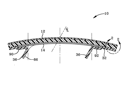
With reference to Figure 6, a typical vehicle
interior is illustrated. A prominent feature of such
vehicle interior is the interior instrument panel or
other trim panel. For example, a typical trim panel
10 includes a trim element 12 which may cover or
overlap a door 14 and frame 16.
The door 14 is inserted into and adhesively
bonded to a substrate 32. The door 14 should be made
of a rigid material of good impact resistance at both
high and low temperatures. A preferred material is a
TPU-NBR blend or a metal such as steel or aluminum.
The frame 16 is generally referred to as the area
of the trim panel 10 near or contiguous to the door 14
and which works together with the door 14 to support
~138183
its movement, just as a door and frame in a house or
other dwelling work together. As illustrated by the
dotted lines, it is preferable that the door 14 and
frame 16 be hidden from view by occupants in the
vehicle interior until deployment of the air bag
through the door 14.
With reference to Figures 1 and 2, the trim panel
10 includes a trim element 12 on an outer side of the
trim panel 10. In the preferred embodiment, the trim
element 12 is 1.5 mm thick and is made of a trim
material. The trim material is preferably
polyurethane or polyurea with an outer paint coating.
The paint coating is also preferably a two component
polyurethane. An alternative construction would be a
cast vinyl trim element 12 with or without a coating.
A further alternative would be a trim element 12 made
of an Thermoplastic Olefin (TPO) sheet or an TPO that
has polypropylene foam laminated to it. In the
preferred embodiment, the trim element 12 is
manufactured by spraying the urethane into a mold as
will be described hereafter.
With continuing reference to Figures 1 and 2, the
next element of the trim panel 10 is a scrim or
reinforcing member 24. As will be later discussed and
illustrated in Figures 3 and 5, the reinforcing member
24 is generally rectangular and positioned around the
door 14 much like a frame is positioned around a
picture, although the reinforcing member 24 is to be
distinguished from the frame 16. The reinforcing
member 24 can be made of any appropriate material such
as scrim might be made of, but is preferably made of a
fabric such as nylon or polyester. The preferred
reinforcing member 24 has a pressure sensitive
adhesive to attach it to the trim panel 10. In an
alternate embodiment the reinforcing member 24 could
~138183
utilize a two component 100% solids urethane adhesive
which is spread onto the trim panel 10. The
reinforcing member 24 is then pressed into the
adhesive and pressed into position.
With continuing reference to Figures 1 and 2, the
next layer of the trim panel 10 is a foam material 28.
The foam material 28 can be any appropriately chosen
adhesive foam, although the preferred foam is a two-
component polyurethane foam based on
polyether/polyesther type polyols with MDI based
isocyanate. In the preferred embodiment, the foam is
between 5 mm and 6 mm thick and has a typical foam
density of between 5.0 and 20.0 pounds per cubic foot
(0.08 grams/cubic centimeter-0.32 grams/cubic
centimeter).
Finally, the panel 10 includes the substrate 32
which is normally manufactured of plastic. The
preferred material is SMA copolymer such as is
available from Arco under the trade name Dylark.
Alternate materials include GE's Noryl EM-7304
polycarbonate, steel, aluminum, magnesium, reinforced
RIM or S-RIM urethanes. The substrate 32 should
provide a molded-in chute for the air bag, i.e.
flanges 36. The flanges 36 are formed into the
substrate 32 and are useful for attaching the air bag
canister (not shown). The substrate has a thickness
of 3 mm to 4 mm.
With reference to Figures 3 and 5, the
reinforcing member 24 and its function will be
described in more detail. Figure 3 is a bottom view
of the inner side of a trim panel 10. The location
and configuration of the door 14 and frame 16 is seen
by the joint 44 which separates them and forms their
respective boundaries.
21381~3
As can be seen with reference to Figure 3, the
reinforcing member 24 is generally rectangular and
surrounds the door 14 much like a picture frame
surrounds a picture. The reinforcing member performs
an important and novel function in that it strengthens
the frame 16 around the door 14 so that the frame 16
near the joint 44 is relatively strong compared to the
door 14. Therefore, when an air bag is inflated in
the process of being deployed, the stresses generated
thereby and impressed upon the door 14 and frame 16
are approximately equal, but the ability of the door
14 to withstand those stresses without significant
deflection is much less than that of the frame 16.
Therefore, the door 14, along the joint 44 breaks
loose, allowing the air bag to be deployed. The door
14 is bonded onto the flange 36 at location 86. A
first adhesive and stronger is used for the upper half
90 of the door 14 while a second and weaker adhesive
is used for the lower half 92 of the door 14. This is
to encourage the leading edge 96 of the door 14 to
open before the upper half of the door 14.
In a preferred embodiment of the invention, the
door 14 is hinged at one side via a door hinge 48. In
such an embodiment, the reinforcing member 24 includes
at least one reinforcing member hinge 52. Upon the
occasion of the deployment of the air bag, the
reinforcing member hinge 52 assists and restrains the
door 14 in its opening and revolution about the door
hinge 48.
With continuing reference to Figure 3, another
important aspect of the preferred embodiment of the
invention is a release element 56 which is configured
on the inner side of the trim panel 10 along the joint
44. Preferably, the joint 44 is coaxial with a
centerline of the release element 56. A preferred
2138183
release element 56 is a wax-based mold release such as
is available from Chemtrend and sold under the trade
name XCTWA4090. The release element 56 assists the
separation of the door assembly 14 from the frame 16
upon deployment of the air bag. It also performs the
important function of preventing foam material 28 from
adhering to the joint 44 or from passing through slits
or punctures 66 in the joint 44.
With continuing reference to Figures 3 and 4, a
further aspect of the preferred embodiment includes
weakened regions 60,61,62. Within the weakened
regions 60,61,62 are weakening means for weakening, or
the punctures or slits 66. The slits 66 have an
initial configuration, immediately after their
formation, as illustrated in Figure 4. The trim
element 12 has an outer side 70 and an inner side 72.
This initial configuration of the slit 66 is generated
by a knife or puncturing tool having the general
configuration of the slit 66. More specifically, the
cutting tool or initial configuration of the slit 66
has a outer surface 74 having a width of about 1 mm
and an inner surface 76 having a width of about 2 mm.
One of the most important aspects of the
invention is the ability of the slit 66 to transform
from its initial configuration, as shown in Figure 4,
to a second configuration where the slit 66 has
essentially disappeared. In such case, the sidewalls
80,82 of the slit 66 move toward each other until they
are adjacent, effectively closing the slit 66. This
quality or characteristic is defined herein as ~self-
healing~ mP~n;ng the punctures or slits 66 used to
create the weakened regions 60,61,62 remain invisible
from the outer side 70 of the trim element 12. This
self-healing characteristic is dependent on the
materials used for the trim element 12. The self-
213gl83
healing characteristic of the trim material also helpsprevent foam material 28 from passing through the trim
material. As stated previously, in the preferred
embodiment, the trim material is a urethane or poly-
urethane material which is preferably sprayed tocreate the trim element 12. While the slit 66 appears
closed and essentially invisible, the trim element 12
is weakened in certain areas by the slits 66.
A preferred method of manufacturing the trim
panel 10 will now be described. The trim element 12
is placed or sprayed into a mold. The substrate 32
with the adhesively bonded TPU-NBR door is positioned
on the lid of the mold. The foam material 28 is then
introduced onto the inner side of the trim element 12
either by pouring into the open moId or by injecting
it into the center of a closed mold. The urethane
foam then reacts and expands to fill the mold and bond
the substrate 32, foam material 28 and trim element 12
together. After the foam has hardened, the mold is
opened and the finished part removed.
The invention has been described with reference
to a preferred embodiment. Obviously, modifications
and alterations will occur to others upon a reading
and underst~n~;ng of this specification. It is
intended to include all such modifications and
alterations insofar as they come within the scope of
the appended claims or the equivalents thereof.