Note: Descriptions are shown in the official language in which they were submitted.
21:38~~6
PATENT
CASE: 1778
DISPOSABLE FILTER FOR DENTAL HANDPIECE
ackg~rosr~zd of the Inventior,~
The present invention is directed generally to
improvements in dental devices and mare particularly to a novel
and improved filter for filtering respective air and water
utility supplies to a hand-held dental device.
Many dental devices used by dentists utilize respective
air and water supplies. Examples of such devices include
handpieces (i.e., high speed dental drills), low speed air
motors, syringes and sealers. Typically, such devices include
a hand-held working portion with which some procedure is
performed on the patient, and a utility supply portion, generally
in the form of an elongate hose or tube through which air and
water supplies to the hand-held portion are provided. The
present application refers specifically to a high speed dental
drill handpiece (hereinafter "handpiece") of the type which
includes an air driven turbine for rotating a bur (i.e., the
drill bit) for drilling the teeth of the patient.
2~.3~~~s _
Heretofore, the air and water supplied to the hand-held
portion or handpiece of such dental devices has not been
filtered_ However, more recently there has been same concern
regarding the presence of airborne and/or waterborne contaminants
in this environment_
In a typical device from two (i.e., one air line and
one water line) to four supply lines are provided in both the
utility supply and in the hand-held portion. In a handpiece
(high speed drill) these lines include a drive air line and an
air exhaust line for driving a turbine portion of the handpiece.
A water line is provided in such handpieces in order to cool the
bur and the tooth of the patient so as to avoid overheating of
the tooth. In this regard, typical rotational speeds of the burs
of such handpieces are on the order of 400,000 rpm. It is
generally preferred that the water supply be in a mist form, and
to this end a secondary air line, often referred to as "chip air"
is also often provided to mist the water from the water supply
line as it leaves the handpiece. This chip air is provided in
one of two forms. In some handpieces, the chip air is bled off
from the drive air supply conduit while in other handpieces, a
separate utility line is provided for chip air_
Many handpieces also include an optical opening through
which a glass tube or fiber optic element is inserted to provide
light near the working end of the handpiece. In same cases such
light is provided in the form of small electric lamp in the
handpiece itself, in which case electrical connectors and
conductors are provided in the handpiece and through the utility
supply hose or tube. In other cases the lamp is provided near
the end of the utility supply tube which carries appropriate
electrical conductors and or connectors for the lamp, and the
illumination from the lamp is fed through a fiber optic light
conductor or other suitable conduit which extends through the
handpiece portion of the device_ In either event, provision for
some sort of lighting requires the provision of an additional
through opening or conduit in both the hand-held portion and the
-2-
___ ~ . ~ ~~3833~
utility supply portion of the dental device, and alignment
thereof .
Typically, such dental handpieces and their utility
supply hoses or tubes are of relatively small diameter to
facilitate easy grasping and maneuvering by the dentist.
Accordingly, the space available within which to run the various
supply lines or conduits, as well as the cross-sectional area
available for providing filtering for these lines is limited.
More particularly, it will be recognized that the cross-sectional
areas or diameters of the respective air and water utility
supplies and their corresponding openings or conduits in both
handpiece and utility supply hose are smaller yet.
As an additional matter, it is currently recommended
that a sterilized handpiece be used for each patient, thereby
requiring that the handpiece be removed from the utility supply
hose and replaced with a sterilized handpiece for each new
patient. Under such circumstances, in order to maintain the
sterile handpieces in a sterile condition, including the internal
conduits for air and water, as well as to prevent cross-
contamination of the utility supply hose or tube, we propose
providing a filter intermediate the hand-held portion and the
utility supply portion of the dental device. We have further
proposed filtering all of the supply lines which run from the
utility supply to the hand-held portion of the device, that is,
not only the drive air but also the exhaust air, as well as the
water and the chip air, in installations were a separate chip air
line is provided in the utility supply.
Heretofore, handpieces have been connected to utility
supply hoses in one of two manners. One type of connection is
a threaded one in which a threaded coupling sleeve is used
intermediate the handpiece and the supply hose. Either the
handpiece has a plurality of tubes projecting longitudinally from
its end part for insertion into corresponding mating openings in
the supply hose, or vice-versa, to interconnect the respective
-3-
_ . ._ .._ 2~~8~~~
lines for air and water, as described hereinabove. The handpiece
and supply hose can also be coupled with a quick
cannect/disconnect type of coupling such as bayonet coupling of
the type shown in prior U.S. Patent No_ 5,039,304, which is
commonly owned herewith_
Therefore, the addition of a filter for the various air
and water utilities to the handpiece must take into account the
particular mating conduit end structures of the hand-held portion
and supply hose, and also the mating coupling or connecting
structures utilized in present dental devices. This is necessary
in order to provide for retrofitting of a suitable filter to
existing dental devices. Such considerations also apply at least
in part to our proposed modified handpiece in which an additional
end cavity portion is specifically provided for mounting such a
filter element, such that the filter element will be interposed
intermediate the air and water supply lines of handpiece and of
the utility supply hose in operation.
-4-
CA 02138336 2004-05-06
64053-298
Obi ects and Summary of the I nvention
Accordingly, it is a general object of this
invention to provide a novel and improved filter for a
dental device.
Briefly, and in accordance with the foregoing, a
filter is provided for a dental device of the type including
a hand-held working portion which utilizes air and water and
a utility supply portion which supplies air and water to
said hand-held working portion through respective air and
water conduits therein. The filter comprises a filter
cartridge body defining an air opening running therethrough
and a water opening running therethrough, said air and water
openings being respectively positioned for alignment with
corresponding air and water openings of one of a hand-held
working portion and a utility supply portion; said filter
cartridge having filtering means for respectively filtering
air and water passing through the respective air and water
openings thereof .
According to one aspect of the present invention,
there is provided a filter in combination with a dental
device, said device including a handpiece having a hand-held
working portion that includes a plurality of conduits for
receiving and discharging water, air or light and a utility
supply portion including conduits for supplying water, air
and light to said working portion and receiving discharges
therefrom, said filter comprising: a filter cartridge
including a cartridge body having a longitudinal axis and
conduits for air, water or light running longitudinally
through said cartridge body, said air and water openings
being respectively positioned in alignment and register with
-5-
CA 02138336 2004-05-06
64053-298
the corresponding air, water and light conduits of said
hand-held working portion and said utility supply portion,
respectively; at least one f filter element comprising a
relatively thin disc-shaped element extending transversely
across said filter cartridge body, mounted within said
filter cartridge and interposed across selected air, water
or light conduits thereof for respectively filtering air
water or light passing there through between the hand-held
working portion and the util ity supply portion of said
dental device; an adapter enclosing said filter cartridge
therewithin, wherein all of said conduits in the working and
supply portions and the filter cartridge of the dental
device are in alignment and registered, said adapter
including, sealing means whereby air, water or light are
transmitted without leakage from said supply portion,
through said filter cartridge body, to said hand-held
working portion and connector means for sealingly connecting
and mounting said adapter, with said filter cartridge body
within, between said hand-held working portion and said
utility supply portion of said dental device.
According to another aspect of the present
invention, there is provided a filter, in combination with a
dental device of the type including (a) a hand-held working
portion which utilizes air and water and (b) a utility
supply portion which supplies air and water to said hand-
held working portion through respective air and water
conduits therein, said filter comprising: a filter
cartridge including a cartridge body having a longitudinal
axis and air and water openings running longitudinally
through said cartridge body, said air and water openings
being respectively positioned for alignment with
corresponding air and water openings of air and water
-5a-
CA 02138336 2004-05-06
64053-298
conduits in facing ends of said hand-held working portion
utility supply portion of the dental device; and at least
one filter element mounted within said filter cartridge and
interposed across at least one of the air and water openings
thereof, filtering air or water passing therethrough between
said hand-held working portion and said utility supply
portion of the dental device, said filter cartridge being
configured for mounting between said hand-held working and
utility supply portions of said dental device, such that all
of said openings are respectively in alignment, register and
sealing connection, wherein said cartridge body further an
elongate through opening for transmitting light from said
utility supply portion to said hand-held working portion of
the dental device.
According to still another aspect of the present
invention, there is provided a dental device, comprising: a
hand-held working portion including conduits for receiving
and discharging air, water or light and a utility supply
portion including conduits for supplying air, water or light
to said hand-held working portion through respective air and
water conduits therein; a filter cartridge including a
cartridge body having a longitudinal axis and air, water or
light conduits running longitudinally through said cartridge
body respectively positioned for alignment with
corresponding air, water or light conduits in facing ends of
said hand-held working portion and said utility supply
portion, respectively; at least one filter element mounted
within said filter cartridge and interposed across the
respective air and water openings thereof for respectively
filtering air and water passing therethrough between said
hand-held working portion and said utility supply portion;
adapter means having an adapter body configured for mounting
-5b-
CA 02138336 2004-05-06
64053-298
said filter cartridge therewithin, wherein all of said
conduits are in alignment and registered within said adapter
whereby air, water or light are transmitted from said supply
portion through said filter body to said hand-held working
portion, said adapter means including sealing means to
prevent leakage between conduits and a connector means for
sealingly mounting said adapter, with said filter cartridge
body within, intermediate said hand-held working portion and
said utility supply portion of said dental device .
According to yet another aspect of the present
invention, there is provided a dental device, comprising: a
hand-held working portion including conduits for receiving
and discharging air, water or light and utility supply
portion including conduits for supplying air, water or light
to said hand-held working portion through respective air and
water conduits therein; a filter cartridge including a
cartridge body having a longitudinal axis and air, water and
light conduits running longitudinally through said cartridge
body respectively positioned for alignment with
corresponding air, water and light conduits of said hand-
held working portion and said utility supply portion,
respectively; at least one filter element mounted within
said filter cartridge and interposed across the respective
air and water conduits thereof for respectively filtering
air and water passing there through between said hand-held
working portion and said utility supply portion; an adapter
configured for mounting said filter cartridge therewithin,
wherein all of said conduits of said dental device are in
sealing alignment or registered whereby air, water or light
are transmitted from said supply portion through said filter
cartridge to said handyheld working portion, said adapter
further comprising connector means for sealingly mounting
-5c-
CA 02138336 2004-05-06
64053-298
said adapter, said filter cartridge therewithin,
intermediate said hand-held working portion and said utility
supply portion of said dental device, wherein said cartridge
body further includes an elongate through opening for
transmitting light from said utility supply portion to said
hand-held working portion.
According to a further aspect of the present
invention, there is provided a disposable filter in
combination with a dental device that includes at least one
conduit for receiving and discharging air or water and a
supply line that includes at least one conduit for
delivering air or water to said device and receiving any
discharge therefrom, said filter comprising: a cartridge
body, interposed between said dental device and supply line,
having at least one axial conduit therethrough coincident
and in register with the conduits of said dental device and
supply line, said cartridge body divided transversally into
at least two body sections; a filter element, relatively
thin and disc-shaped, fitted to and extending transversally
across and sandwiched between said cartridge body sections,
said body sections supporting major surfaces of said filter
element, said filter element filtering at least one conduit
between said dental device and said supply line; and an
adapter configured for sealably containing said filter
cartridge body therein with all said air and water conduits
between the dental device and supply line in alignment and
register with those in the cartridge body, said adapter
further including connector means for mounting said adapter,
containing said disposable filter, between said dental
device and said supply line.
-5d-
CA 02138336 2004-05-06
64053-298
According to yet a further aspect of the present
invention, there is provided a disposable filter for a
dental device, including a handpiece that includes a
plurality o f conduits in combination with receiving and
discharging air, water or light and a supply portion that
includes conduits for delivering air, water or light to said
handpiece and receiving discharge therefrom, said filter
comprising: a cartridge body interposable between said
handpiece and supply portion having a plurality of conduits
therethrough~ coincident and in register with the plurality
of conduits of said handpiece and supply portion, said
cartridge body divided transversally into at least two body
sections; a filter element, relatively thin and disc-shaped,
fitted to and extending transversally across and sandwiched
between said cartridge body sections, said body sections
supporting said filter element, said filter element
partially obstructing at least one conduit for filtering and
otherwise apertured to transmit air, water or light
therethrough unobstructed; and an adapter configured for
sealably containing said cartridge body therein with said
conduits of the handpiece and supply portion in register and
sealing contact with those in the cartridge body, said
adapter further including connectors for mounting said
adapter, containing said disposable filter, intermediate
between said handpiece and said supply portion .
-5e-
213336
Brief Description of the Drawings
The features of the present invention which are
believed to be novel are set forth with particularity in the
appended claims _ The organization and manner of operation of the
invention, together with further objects and advantages thereof
may best be understood by reference to the following description,
taken in connection with the accompanying drawings in which Like
reference numerals identify like elements, and in which:
l0
Fig. 1 is a perspective view of a dental device
including a handpiece and utility supply hose, and provided with
a filter in accardance with the invention;
Fig. 2 is an enlarged partial exploded perspective view
of the device of Fig. 1;
Fig. 3 is a partial sectional view through a filter
cartridge and adapter in accordance with one form of the
invention;
Fig. .4 is a partial sectional view similar to Fig. 3
illustrating a bayonet type connection;
Fig. 5 is an end view of a filter cartridge in
accordance with one form of the invention;
Fig. 6 is a sectional view taken generally along the
line 6-6 of Fig. 5:
Fig. 7 is a sectional view taken generally along the
line 7-7 of Fig. 5:
Fig. 8 is a sectional view taken generally along the
line 8-8 of Fig.. 5;
-6-
213833
Fig. 9 is an enlarged partial sectional view similar
to Fig_ 7 showing an alternate form of a filter element in
accordance with the invention: and
Fig_ 10 is an enlarged partial side elevation,
partially in section, illustrating an assembled dental device
similar to that of Fig_ 1, including a modified filter in
accordance with the invention_ _
-~ 2~38~3~
detailed Description of the Illustrated Embodiment
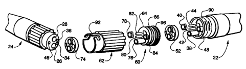
Referring now to the drawings, and initially to
Figs_ 1 and 2, there is illustrated a dental device 20 of the
type which includes a hand-held working portion 22 and a utility
supply hose or tube portion 24 operatively coupled to the hand-
held portion 22 _ In the illustrated embodiment the hand-held
portion 22 comprises a high speed dental drill handpiece
(hereinafter referred to as "handpiece"). The handpiece
22
receives both air and water supplies from the utility supply
or
hose 24. A hand-held working portion of a different sort, for
example a low speed air motor, a syringe, or a sealer implement
might be utilized with a similar utility supply 2 4 without
departing from the invention.
The utility supply, as best seen in Fig. 2 includes
elongated through tubes or conduits for supplying air and water
respectively to the handpiece 22. In the illustrated embodiment,
these air and water conduits include a drive air supply conduit
26 and an exhaust air conduit 28 for supplying air to and
exhausting air from a turbine (not shown) which drives a bur 30
of the handpiece, this turbine being located in the head portion
32 of the handpiece 22. Water is provided for cooling the bur
and the tooth of the patient through a water supply conduit
25 34 and so-called chip air is provided through an air conduit 36.
This chip air is used to mist or atomize the water, which has
been supplied through the water conduit 34, at the head 32. In
the handpiece 22 of Fig. 1 the water outlet is indicated
generally at reference numeral 38 where it exits adjacent the
30 head 32.
Similar conduits are provided within the handpiece 22
for matingly engaging the open ends of the conduits just
described in the utility supply hose 24. These conduits
generally project outwardly from the head so as to enter into the
corresponding end openings of the hose conduits . These handpiece
_g_
~~c~~~~~
conduits include a drive air supply conduit 38, an exhaust air
conduit 40, a water conduit 42 and a chip air conduit 44.
An additional optical opening or conduit is provided
through which a fiber optic or other light source may be provided
to illuminate the work area adjacent the head 32. This light
conduit is indicated by reference numeral 46 in the hose 24 and
by reference numeral 48 in the handpiece 22_ The illumination
is provided generally at a window or opening 50 adj acent the head
32 as shown in Fig. 1. A suitable sealing gasket 52 may be
provided intermediate the handpiece 22 and the utility supply
hose 24.
The above-described structure is generally similar to
Z5 that illustrated and described in U. S . Patent No . 5 , 03 9 , 3 OS which
is commonly owned herewith, and in which the handpiece 22
directly couples to the utility supply hose 24 by means of a
suitable adapter.
Departing from what is shown in this prior patent, the
present invention advantageously interposes a filter cartridge
60 intermediate the handpiece 22 and the utility supply hose 24_
In the embodiment illustrated herein the filter cartridge 60 is
arranged to be held in an adapter 62, similar to the adapter
shown in the above-reference patent, but lengthened somewhat in
order to accommodate the filter cartridge 60_ However, the
filter cartridge 60 could be accommodated within a modified
handpiece 22 or within a modified utility supply portion 24,
without departing from the invention.
The filter cartridge 60 includes cartridge body 64
which includes a plurality of through conduits generally aligned
with the respective air and water conduits of the handpiece 22
on the one side and of the utility supply hose 24 on the other
side, these latter conduits having been described hereinabove.
The filter cartridge 60 in the illustrated embodiment has air and
water conduits which at one end are generally identical in form
-9-
238336 _._ _
to the open ends of the conduits of the supply hose 24 and at the
other end are generally identical in form to the projecting
conduits of the handpiece 22, such that the filter cartridge 60
directly interfits between the handpiece 22 and supply hose 24.
To this end, an additional gasket 74 substantially identical to
gasket 52 is interposed between the supply hose and the filter
cartridge 60, while the first gasket 52 is interposed between the
filter cartridge 60 and the handpiece 22.
Referring also to Figs. 3-8, the conduits of the filter
cartridge 60 are identified as follows: drive air supply 76,
exhaust air 78, water 80, chip air 82 and optical or light 84.
An O-ring 86 is provided in the illustrated embodiment for
sealing the exterior surface of the cartridge 60 with respect to
a facing interior surface of the adapter 62, or of the handpiece
22, when a modified handpiece for accommodating the filter
cartridge is provided, as mentioned above_
As shown in Figs. 3 and 4, the adapter 62 is provided
with suitable connectors at its ends for connection to the
handpiece 22 on one side and to the supply hose 24 on the other
side _ The connector for connection to the handpiece 22 comprises
an internally threaded surface 88 configured for mating
engagement with an external thread 90 of the handpiece 22. In
the embodiment illustrated in Figs. 2 and 4, the connector for
engagement with the supply hose 24 comprises quick connect or
bayonet type connector 92. In this regard, the bayonet or quick
connect type connector 92 and suitable mating pins (not shown)
for engaging the same in the utility supply hose 24 are
preferably as illustrated and described in the above-referenced
U.S. Patent No. 5,039,304. In the embodiment illustrated in
Fig. 3, the adapter 62 includes a second externally threaded
connector 94 for connection to a complementary thread (not shown)
of a utility supply which is otherwise the same as the utility
supply hose 24 illustrated in Fig_ 2. In the illustrated
embodiment, the cartridge body 60 also includes a somewhat
enlarged diameter end portion 96 for engagement with a
-10-
.:. _ 213~~,~~
corresponding mating shoulder or step portion 98 formed within
the adapter 62 for engaging and positioning the filter cartridge
therewithin.
Referring now to Figs_ 5-10, the cartridge body 64
includes an annular circumferential groove 98 for accommodating
the O-ring 86. As best viewed in Fig_ 8, the light or optical
conduit 48 comprises an elongate through opening through the
cartridge body 64. An additional optical transmitting element
such as a prism or fiber optic element 100 may be inserted in the
opening 48 to enhance the transmission therethrough and through
the filter cartridge, so as to minimize the light loss through
the filter cartridge.
In the embodiment shown in Figs. 5-9, the filter
cartridge is composed of first, second and third body portions,
102, 104 and 106, each of which comprises a generally cylindrical
body. These body portions 102, I04, 106 are coaxially aligned
and of the same outer diameter in the preferred embodiment
illustrated_ The body portions 102, 104, 106 are spaced apart
by narrow gaps, in which are fitted respective first and second
filter elements 108, 110. The filter material selected for
forming filter elements I08 and 110 will be of a selected
porosity for excluding particles above a certain size. Various
filter pore sizes might be selected in this regard, depending
upon the type of viral, bacterial or other contaminants to be
filtered.
Referring briefly to Fig. 9, should an additional
effective surface area of the filter be desired, an elongate
tubular closed-ended portion of one or both filter elements might
be formed extending into the conduit with which it is associated.
One such extended tubular closed-ended portion of the filter
element I08 is indicated at reference numeral 112 in Fig. 9,and
extends into the conduit 42.
-I1-
°
2138336
Fewer or more such filter elements and a corresponding
number of body portions might be provided as desired without
departing from the invention. For example, it is possible that
one of the filter elements 108, 110 may serve to filter the water
line while the other might serve to filter the three air lines
or conduits. On the other hand, both of the filter elements 108
and 110 may extend across and filter all of the air and water
lines or conduits, if desired in a particular application.. In
any event, all of the filter elements are provided with through
l0 openings through which the optical channel 84 and/or an optical
element 100 contained therein may pass unimpeded as illustrated
in Fig. 8.
In the embodiment shown in Fig. 10, a single filter,
element 110 is positioned between two cartridge body portions
102a, 106a. It should be noted that the partial section shown
in Fig. 10 is developmental in form, indicating a development or
section which bisects the drive air supply conduit 76 and the
water conduit 80. A portion of the optical conduit 48 of the
handpiece 22 is also shown in Fig. 10, entering the filter
cartridge 60.
In the illustrated embodiments, the body portions 102,
104 and 106 or 102a, 106a are generally coaxially aligned and
have their outer circumferences or peripheries aligned_
Similarly, the filter elements 108 and 110 preferably comprise
relatively thin disk-shaped circular elements which are coaxially
aligned with the filter cartridge body 64 and which have outer
diameters sized the same as the outer diameter of the filter body
64 and its body portions 102, 104 and 106, or lO2a and 106a.
Thus, an external surface of the filter body is substantially
continuous and cylindrical in form with the exception of the
proj ecting holding portion 96 and the O-ring receiving groove 98
Also, the filter cartridge has smaller external cross-sectional
dimensions than those of the handpiece 22 and utility hose 24.
Accordingly, as shown in Fig. 1, the dental device incorporating
the filter cartridge 60 operatively interposed between handpiece
-12-
2~.38~~6 _ . _ .
22 and utility hose 24 is permitted a smooth merger of its
external surfaces _
While particular embodiments of the mention have been
shown and described in detail, it will be obvious to those
skilled in the art that changes and modifications of the present
invention, in its various aspects, may be made without departing
from the invention in its broader aspects, some of which changes
and modifications being matters of routine engineering or design,
l0 and others being apparent only after study. As such, the scope
of the invention should not be limited by the particular
embodiment and specific construction described herein but should
- be defined by the appended claims and equivalents thereof.
Accordingly, the aim in the appended claims is to cover all such
changes and modifications as fall within the true spirit and
scope of the invention.
y.
-13-