Note: Descriptions are shown in the official language in which they were submitted.
~ ~ .
- 2~38341.
FIELI) OF THE INVENIION
The present invention pertains to a crate for holding packages. More
particularly, the present invention relates to a foldable crate for holding
packages such as gable-top type packages.
BACKGROUND OF 1~ INVENTION
Packages that contain various types of products such as, for eY~mple,
liquids, are usually transported by placing the packages in a shipping crate.
Typically, the crates are ~imen~ioned to receive and hold a plurality of such
packages so that numerous packages can be easily shipped.
Crates used for the foregoing purpose are oftPntimPs constructed as a
one-piece rigid unit. Although such crates serve the intended purpose of
allowing the crates to be more easily transported, they do suffer from certain
disadvantages and drawbacks. For example, before the packages are placed
in the crate for shipment to the distributors, the crates must be stored in
lS some area of the p~c~ging facility. Since the crates cannot be reduced in
size due to their rigid construction, a large storage area is typically requiredto store the crates. From a m~nuf~cturing standpoint, it may not be cost
effective to utilize a large portion of the p~c~ging plant for storing the
empty crates.
In addition, after the packages have been removed from the crates,
the empty crates must be transported back to the distributor or to the
packaging plant. Once again, the rigid construction of the crates requires a
large amount of storage space for transporting the empty crates.
- 213~34~.
Further, the rigid nature of the crates makes them particularly
attractive for use in constructing ru~im~nt~ry tables, shelving and the like.
Thus, it has been found that the rigid crates are frequently stolen for use as acheap rulllilure component.
In view of the roregoing, a need exists for a crate for holding
packages that is not susceptible to the same disadvantages and drawbacks
noted above.
OBJECTS AND SIJMMARY OF THE INVENTION
The present invention provides a crate for holding packages that is
well suited for addressing at least the foregoing disadvantages and drawbacks
~soci~ted with other known crates. The crate according to the present
invention is foldable, thereby recluting the amount of storage space required
to store and transport the crates. In addition, because the crate is foldable, it
is not as attractive to would-be thieves seeking to use the crate as a
s.lp~lling colll~nent of a shelving system.
In accor-lance with one aspect of the present invention, a folding
crate for holding packages inch~des a base having a subst~nti~lly planar
support surface and four sides walls which are each located along one of the
- sides of the base. Each side of the base is provided with a hinge pin
20 member having a longitutlin~l axis that is vertically spaced from the plane of
the support surface. Each of the pin members is generally oval or elliptical
in cross-section with the minor axis of the cross-section being positioned
2~ 41
subsPnti~lly parallel to the plane of the support surface and the major axis of
the cross-section being positioned subsPnti~lly perpendicular to the plane of
the support surface. Each of the side walls has at least one knuckle
eYtPn-ling from the lower end. The knuckle on each side wall has a
5 subst~nti~lly circular through hole which loosely receives the hinge pin
member so that the side wall can be pivoted from an upright position to an
inwardly folded position. The knuckle on each side wall is provided with a
slotted opening which extends through a wall of the knuckle and into the
through hole for allowing the side wall to be mounted on the respective
10 hinge pin member. The slotted opening possesses a width that is less than
the ~limen~ion of the cross-section of the hinge pin member as measured
along the major axis. In addition, at least one of the side walls is provided
with a protuberance on the outer surface that extends oulwar~ly away from
surrounding areas of the side wall. The protuberance is hollow and has an
15 open lower end for receiving a tool for use in moving the crate and a
plurality of other cratçs stacked thereon.
Another aspect of the present invention involves a folding crate for
holding packages that incllldes a base having a ~ub~l~nl;~lly planar support
surface for supporting packages and a plurality of sides walls which are each
20 provided with a knuçkle at the bottom end. The base possesses a plurality of
sides which are each provided with a hinge pin member. The hinge pin
member possesses a cross-sectional shape in which a first ~1im~n~ion of the
cross-sectional shape along a line extending subst~nti~lly perpendicular to the
21~ 41.
-
plane of the support surface is greater than a second ~limensiQn of the cross-
sectioned shape along a line eYten~ling subst~nti~lly parallel to the plane of
the SLIl?pOll s~ e The knuckle on each of these side walls is provided
with a through hole which loosely receives one of the hinge pin members for
5 allowing the side wall to be moved from an upright vertical position to an
inwardly folded position. The knuckle on each of these side walls incl~ldes a
slotted opening which extends through a wall of the knuckle and which
communicates with the through hole in the kml~kle to allow the side wall to
be mounted on the hinge pin member. The slotted opening possesses a
10 width that is less than the first tlim~.n~ion of the cross-sectional shape of the
hinge pin member.
In accordallce with another aspect of the present invention, a folding
crate for holding packages in~.ludes a base having a substantially planar
support surface for supporting packages and a plurality of sides walls which
15 are each located on one of the sides of the base. Each side of the base is
provided with a hinge pin member which pos~ ses a longih~in~l axis that is
vertically spaced above the plane of the support s-lrf~e. The longitudin~l
axis of each of the hinge pin members is vertically spaced from the plane of
the support surface by a different distance. Each of the side walls is
20 provided with a knuckle for mounting the side wall on a respective one of
the hinge pin members. Each of the hinge pin members is loosely received
in a through hole that is provided in the knuckle of a lcs~ecli~e side wall so
that each side wall can be moved from an upright vertical position to an
213834~
inwardly folded horizontal position. One of the side walls is constructed
such that a center of gravity of the one side wall is located inwardly of the
lon~itu-lin~l axis of the ~ e hinge pin member when the one side wall
is in the upright vertical position.
S A further aspect of the present invention involves a folding crate for
holding packages that includes a base having a subst~nti~lly planar support
surface for ~uppolling packages and a plurality of side walls mounted on the
base. At least one of the side walls is provided with a protuberance on the
outer surface that extends oulw~rdly away from surrounding areas of the side
wall. The protuberance has a front surface and side su~f~ces which define a
hollow area, and a lower end of the protuberance is open to the hollow area
to allow a tool to be inserted through the open end and into the hollow area
for use in moving the crate and a plurality of other crates stacked thereon.
BRIEF DESCRIPIION OF l~lE DR~WING FIGURES
A prefe~d embodiment of the present invention will be described in
greater detail with reference to the accolllpanyillg drawing figures in which
like elem~nt~ are i~Pntifi~d by like reference numerals and wherein:
FIG. I is a top perspective view of the folding crate according to the
present invention showing gable-top type packages in the crate;
FIG. 2 is a top perspective view of the base which forms a part of the
folding crate of the present invention;
2138;341.
-
FIG. 3is a top view of the side walls of the folding crate showing theintereng~ging ~olenn~nt~ on the side walls that help ~ in the side walls in
a vertical ori~.nt~tion;
FIG. 4is a cross-sectional view through the base and a portion of the
5 side wall of the crate illustrating the hinge arrangement that allows the side
walls to be folded inwardly;
FIG. 5 is a cross-sectional view similar to FIG. 4 illustrating the way
in which the side wall is mounted on the base;
FIG. 6is a side view showing how the crates stack on top of one
10 another when the side walls of the crates are folded inwardly;
FIG. 7is another side view showing how the crates stack on top of
one another when the side walls are in the upright vertical position;
FIG. 8is a front view of one of the side walls that is mounted on the
base of the crate;
FIG.9 is a top view of the side walls of another embodiment of the
folding crate showing the interen~ging elennPnt~ on the side walls that help
m~int~in the side walls in a vertical orientation; and
FIG. lOis a cross-sP,ction~l view along the section line 10-10 in
FIG. 8 illustrating the protuberance that is formed in the side walls for
20 allowing a stack of crates to be dragged along a floor with the aid of a hook.
2~3~34~
DETAn ~O DESCRIPIION OF THE PREF~RR~l- EMBODIMENTS
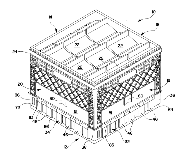
With reference initially to FIG. 1, the crate 10 according to the
present invention inclu~es a four-sided base 12 and a plurality of side walls
mounted on the base 12. The plurality of side walls include a first side
S wall 14, a second side wall 16, a third side wall 18 and a fourth side
wall 20. The crate 10 is shown in FIG. 1 with the side walls 14, 16, 18, 20
in an upright vertical position for receiving packages such as gable-top type
cartons 22. When the packages 22 have been placed in the crate, an
encircling strap 24 is placed around the outer periphery of the side
walls 14, 16, 18, 20 to impart rigidity to the crate 10 by tightly holding
together the upst~n~ling side walls 14, 16, 18, 20. The oulwa~-lly facing
corners of the side walls 14, 16, 18, 20 can be provided with a recess or the
like to receive and pr~ ly position the strap 24 around the side walls.
Also, more than one strap can be utilized if desired. The strap 24 can
15 consist of a length of plastic whose ends have been heat welded together.
As seen in FIG. 2, the base 12 is provided with a generally planar
support surface 26 for s.lp~ g packages. The support surface 26 can be
char~tP-ri~ed by a waffle-type pattern of through ope-nin~. In that way, the
overall weight of the crate 10 and the amount of m~tPri~l required to
20 fabricate the crate 10 can be reduced.
The base 12 includes four upst~nfling sides 28, 30, 32, 34. The first
side wall 14 is mounted on the first side 28 of the base 12, the second side
wall 16 is mounted on the second side 30 of the base 12, the third side
21;~R341.
wall 18 is mounted on the third side of the base 12, and the fourth side
wall 20 is mounted on the fourth side 34 of the base 12. Each comer of the
base 12 is also provided with an upst~nding ~u~po~ g post 36 which, as
will be described in more detail below, allows the crates to be stacked on top
of one another when the side walls 14, 16, 18, 20 are folded inwardly. The
tops of all of the suppo~ g posts 36 are preferably coplanar to permit even
st~c1ring of the crates.
The base 12 is also provided with an arrangement for allowing each
of the side walls 14, 16, 18, 20 to be hingedly mounted on the respective
side of the base 12 so that the side walls 14, 16, 18, 20 can be moved from
an upright subst~nti~lly vertical position to an inwardly folded subst~nti~lly
horizontal position. That arrangement includes a hinge pin member 40
disposed on each side 28, 30, 32, 34 of the base 12. The hinge pin
member 40 possesses a longitudin~l axis that is parallel or subst~nti~lly
parallel to the plane of the support surface 26. In addition, the longit~l-lin~laxes of the hinge pin members 40 associated with each of the sides 28, 30,
32, 34 of the base 12 are located at different ~ t~nces from the plane of the
support surface 26. More particularly, the lon~ituflin~l axis of the hinge pin
member 40 located along the first side 28 of the base 12 is located closest to
the plane of the support surface 26 while the longitu-lin~l axis of the hinge
pin member 40 associated with the fourth side 34 of the base 12 is located
farthest from the plane of the support surface 26. The longit~ in~l axis of
the hinge pin member 40 ~soci~te~ with the second side 30 is located
- Z13~3~41.
farther from the plane of the support surface 26 relative to the longitll-lin~l
axis of the hinge pin member 40 on the first side 28 of the base 12, Also,
the longit l-~in~l axis of the hinge pin member 40 associaled with the third
side 30 of the base 12 is located farther from the plane of the support
S surface 26 than the longiturlin~l axis of the hinge pin member 40 associated
with the second side 32 of the base. Thus, as viewed in FIG. 2 and
extending in a clockwise direction begi,-ning with the first side 28, the
longituflin~l axis of the hinge pin member 40 associated with each s~lcce~ive
side of the base is located at increasing vertical distances from the plane of
10 the support surface 26.
Preferably, the longitu~in~l axis of the hinge member 40 associated
with each side of the base 12 is spaced apart from the longitu-lin~l axis of
the hinge pin member 40 associated with the preceAin~ side by a ~ t~n~e
approximately equal to the thickn~,~s of the side walls. Such an arrangement
allows the side walls 14, 16, 18, 20 which are mounted on the sides 28, 30,
32, 34 of the base 12 to be successively folded inwardly to a generally
horizontal orient~tion.
Each of the hinge pin members 40 comprises a plurality of spaced
apart hinge pin segm~,nt~ 42 ~dj~ nt hinge pin segments 42 located along
20 each side of the base 12 are spaced apart by upst~ntling side wall
suppolls 44. The hinge pin segments 42 are formed integrally and in one
piece with the side wall supports 44 as well as with the rem~in.1~,r of the
base 12. That is, the hinge pin s~ogment~ cannot be removed. As will be
21::~8341.
-10-
described in more detail below, the side wall :iU~?Oll:~ 44 provide a support
for the side waUs 14, 16, 18, 20 when the side walls are in the upright
vertical position. In addition, when the crates 10 are filled with packages
and stacked on top of one another, the side wall ~uppoll~ 44 help transfer the
5 load to the base 12.
A plurality of spaced apart reinforcing el~PmPnt~ 46 can also be
disposed along each side 28, 30, 32, 34 of the base 12. Each of the side
walls ~uppolls 44 preferably extend between adj~cent reinforcing elernPnt~ 46
so that the load tr~n~mitted to the side wall SuppGlL~ 44 is tr~n~mitted to the
10 reinforcing elemPnt~ 46 and then to the base 12. As an ~ltPrn~tive to the
reinforcing elements 46, the portion of each side 28, 30, 32, 34 of the base
12 located below the side wall supports 44 can be fabricated to have a
subsPnti~lly constant thicknPs~
FIG. 8 illustrates the first side wall 14 as viewed from the side that
15 faces ou~w~dly when the side wall is mounted on the base 12. The fealules
associated with the first side wall 14 are also çh~r~-~tPrist1c of the other side
walls 16, 18, 20, except that the height of each of the side walls (i.e., the
~i~t~nce between the top and bottom edges of the side walls) differs. As
seen in FIG. 8, the side wall is generally rectangular in shape. The top
20 portion 90 and vertical side portions 92 of the side walls are provided with a
pattern of through holes defined by a criss-cross arrangement of reinforcing
ribs. A series of recessed regions also defined by a criss-cross arrangement
of reinforcing ribs is provided in the middle portion 94 of the side walls and
~ ' ~
2~ 3~
a recessed area which is absent the reinforcing ribs is provided along the
lower portion 81 of the side walls.
An opening 49 that serves as a handle for f~ilit~ting the lifting of the
crate can be provided at the top region of the side wall 14. A plurality of
S spaced apart knUc~les or lugs 48 extend from the bottom edge of the side
wall 14 for allowing the side wall 14 to be mounted on the respective side of
the base. Located between ~ ,ent knuckles 48 at the bottom edge of the
side wall are a plurality of spaced apart support s~ ces 58.
FIGS. 4 and 5 illustrate cross sections through the first side 28 of the
base 12 when the first side wall 14 is mounted on the base 12. It is to be
understood, however, that the fealures depicted in FIGS. 4 and 5 are also
characteristic of the way in which the other side walls 16, 18, 20 are
mounted on their respective sides 30, 32, 34 of the base 12. As seen in
FIG. 4, each of the knuckles 48 disposed along the bottom edge of the side
15 wall 14 is provided with a generally circularly shaped through hole 50 which
freely receives one of the hinge segments 42 disposed along the first side 28
of the base 12. The wall of each knuckle 48 is also provided with a slotted
opening 52 that co~ tes`with the through hole 50.
As can be seen from Figs. 4 and 5, the hinge segm~nt 42 which is
20 loosely received in the hole 50 of the kmlc~le 48 possesses an oval or
elliptical cross-sectional shape. All of the hinge segments 42 ~icpose~ along
the four sides 28, 30, 32, 34 of the base possess the same oval or elliptical
cross-sectional shape. The major axis of the elliptical or oval cross-section
2~3~ 41
is orient~ perpen~ic~ r or subst~nti~lly perpendicular to the plane of the
support surface 26 while the minor axis is oriented parallel or subst~nti~lly
parallel to the plane of the support surface 26. Thus, the sm~llest dimen~ion
of the elliptical cross-section is directed along a line passing through the
5 center of the cross-section and parallel or sub~ lly parallel to the plane
of the support surface 26. The greale~ imPn~iQn of the hinge se~ment
cross-section is located along a line passing through the center of the cross-
section and oriented perpendicular or subst~nti~lly perpendicular to the plane
of the support surface 26.
The width across the slotted opening 52 is specifically selected to be
less than the largest ~im~PnSion of the hinge pin segrnPnt cross-section (i.e.,
the distance along the major axis). On the other hand, the width across the
slotted opening 52 is preferably equal to or subst~nti~lly equal to the sm~llest
~imPn~ion of the hinge pin segm~Pnt cross-section (i.e., the ~i~t~nce along the
15 minor axis).
The hinge arrangement shown FIGS. 4 and 5 allows the side walls 14
to be easily mounted on the respective side 28 of the base 12 and yet
prevents the side wall 14 from being ~i~Png~ged from the base when the side
wall is in the upright vertical position. That is, with the side wall located in
20 a horizontal position and positioned outwardly with respect to the support
surface 26 as shown in FIG. 5, the slotted opening 52 in each of the
knucldes 48 is oriented dowllwardly. Since the width across the slotted
opening 52 is subst~nti~lly the same as the na,rowe~ imPn~ion of the hinge
2138~1
pin segm~nt cross-section, the hinge pin segment 42 easily passes through
the slotted opening 52 when the side wall is mounted on the base 12. It is,
of course, to be understood that the width across the slotted opening 52 can
be slightly smaller or larger than the na~ e~l ~im~n~ion across the hinge
5 pin segm~nt cross-section depending upon, for example, the pliability of the
plastic m~teri~l from which the side wall 14 is fabricated.
Once the side wall 14 is mounted on the base 12 in the manner shown
in FIG. 5, the side wall 14 can be pivoted upwardly to the vertical upright
position shown in FIG. 4. When positioned in the upright vertical position
10 shown in FIG. 4, the slotted opening 52 faces oulwa~dly and the orient~tion
of the slotted opening 52 relative to the elliptical cross-section of the hinge
pin segment 42 inhibits or prevents the side wall 14 from being readily
removed from the side of the base 12. Thus, the side wall 14 can be easily
mounted on the base 12, but is not susceptible to inadvertent removal during
15 use of the crate.
FIGS. 4 and 5 also illustrate an upst~n~ing support ledge 56 that is
disposed at the top end of each of the side wall suppolli 44. As can be seen
in FIG. 4, when the side wall 14 is in the vertical upright position, and
particularly when a load is applied through the side wall 14 (such as would
20 occur when the crates are stacked on top of one another), the side wall 14
rests upon the support ledge 56. Preferably, a small amount of play is
provided belween the hinge pin segmPnt 42 and the through hole 50 in the
kn~-ckle so that when the side wall 14 is in the vertical upright position, the
;~3~
support surf~ces 58 at the bottom edge of the side wall bear directly against
the support ledge 56 of the base 12. Thus, the hinge pin segment.~ 42 will
not be subjected to the full loading force tr~n~mitted through the side wall
14. Rather, loads tr~n~mitted through the side wall 14 will be transferred to
5 the base 12 by way of the side wall ~ul)poll~ 44 and the reinforcing element~
46. In that way, potential damage to the hinge pin segments 42 can be
avoided.
In addition, by providing play between the hinge pin segments 42 and
the through openings 50 in the knuckles 48, the support surfaces 58 at the
10 bottom edge 58 of the side wall 14 will be able to clear the top surface of
the support ledge 56 when the side wall 14 is pivoted from the horizontal
position shown in FIG. 5 to the vertical upright position shown in FIG. 4.
Once the side wall 14 has been mounted on the respective side 28 of the
base 12 and has been moved to the upright vertical position shown in FIG.
4, the support ledge 56 prcvellls the side wall 14 from inadvertently pivoting
oulwardly. Through the application of a force sllfficient to overcome the
rerellce between the support surface 58 and the support ledge 56, the
side wall 14 can be pivoted oulwardly once again to the position shown in
FIG. 5. ~ that position, the side wall 14 can be removed from the base 12
20 if desired.
As an ~lt~.rn~tive to the arrangement shown in FIGS. 4 and 5, the
side walls could be designed in a manner that would permit them to be
mounted on the respective sides of the base 12 when the side walls are
2~38341
-15-
horizontally positioned in ov~llyillg relation to the support surface 26. In
such an ~ltern~tive arrangement, the slotted openings 52 in the knuckles 48
would face dowllw~dly when the side walls are mounted on the hinge pin
members 40 and would face inwardly when the side walls are in the upright
vertical position.
The crate 10 according to the present invention as shown in FIG. 1 is
desip~n~d so that the first side wall to fold inwardly is the first side wall 14,
the next side wall to fold inwardly is the second side wall 16, the third side
wall to fold inwardly is the third side wall 18 and the final side wall to fold
inwardly is the fourth side wall 20. Thus, as can be seen in FIG. 1, when
the side walls 14, 16, 18, 20 are in the upright vertical position, both
vertical sides of the first side wall 14 are positioned belween the inwardly
facing inner surfaces of the second and fourth side walls 16, 20, one side of
the second side wall 16 faces the inwardly facing inner surface of the third
side wall 18 while the opposite side of the second side wall 16 is exposed,
one vertical side of the third side wall 18 faces the inwardly facing inner
surface of the fourth side wall 20 while the opposil~ vertical side of the thirdside wall 18 is exposed, and both vertical sides of the fourth side wall 20 are
exposed.
The side walls 14, 16, 18, 20 are also provided with an arrangement
for providing interengagement bc;lweell ~dj~cPnt side walls. With reference
to FIG. 3, the inwardly facing inner surf~s of certain side walls have
projections 70 e~ten-ling theler,olll for eng~ging blind holes 68 that are
213~3;341.
-16-
provided on the sides of mating side walls. The blind holes 68 are
completely surrounded on all sides by portions of the ~ e side walls.
The interengagement between the projections 70 and the blind holes 68 helps
propclly orient the side walls 14, 16, 18, 20 in a vertical oriPntAtion so that
S the strap 24 can be placed around the outer periphery of the side walls.
More than one projection 70 and blind hole 68 can be provided on each of
the respe~ e sides and inner s~ ce~ of the side walls if desired. In
addition, longit~l-linAlly extending projecting elements 72 can be provided
~djA~ent the projections 70 for çng~ging the inwardly facing inner surfaces of
10 the respective side walls to help further ~"Ain~in the vertical ori~ntAtion of
the side walls. The projecting elements 72 can extend longitu-linAlly along
the inner sllrfAces of the respective side walls for a predetermined ~i~t~nce.
After the packages 22 have been removed from the crate 10, the strap
24 can be removed to permit the inward folding of the side walls 14, 16, 18,
15 20. As noted above, the crate is designed so that the first side wall 14 is the
initial side wall to be folded inwardly. The crate is also preferably designed
so that the first side wall 14 automAtic~lly falls inwardly upon removal of the
strap 24. To achieve this result, the first side wall 14 is constructed so that
when it is in the upright vertical position, its center of gravity is locate~d
20 inwardly with respect to the longitu~inAl axis of the hinge pin member 40
located along the first side 28 of the base 12. Once the strap 24 has been
removed, the projections 70 and the blind holes 68 tend to (li~-ngAge from
one another and the first side wall 14 aulo~ lly falls inwardly due to the
21~8:~41.
fact that its center of gravity is located inwardly of the lon~itu-lin~l axis of
the ~soci~t~d hinge pin member 40. In addition, the other side walls 16,
18, 20 are preferably de-~ignPd so that their l~ive centers of gravity are
located oulw~dly with respect to the longitu~in~l axis of the hinge pin
S member on which they are respectively mounted. Once the first side wall 14
has fallen inwardly, the second, third and fourth side walls can be easily
pushed inwardly in that order. Thus, the crate according to the present
invention autom~ti(-~lly identifiPs the first side wall that is to be folded
inwardly.
A crate which is de~ign~d so that the first wall tends to autom~ti~lly
fall inwardly upon the removal of the packages 22 and the strap 24 requires
a two step operation in order to fold the sides of the crate. That is, the strap
24 must first be removed which typically requires that the strap 24 be cut or
otherwise designed so that its ends can be sepa~led. Once the strap 24 has
been severed, the side walls must then be folded inwardly. As an
;ve, the crate can be designed to f~ilit~te a single step operation.
FIG. 9 illustrates an arrangement of intereng~gin~ features for the side walls
14, 16, 18, 20 that p~ s such a single step operation.
As seen in FIG. 9, the third side wall 18 is the same as the third side
wall 18 shown in FIG. 3. In addition, the side of the second side wall 16'
and the side of the fourth side wall 20' which are located closest to the third
side wall 18 are the same as in the FIG. 3 embodiment (i.e., a blind hole 68
is provided in the side of the second side wall 16' while a projection 70 and
Z13~3~4i.
-18-
a projecting element 72 are provided on the inwardly facing inner surface of
the fourth side wall 20'). The dirre~ ce lies in the first side wall 14' and
the sides of the second and fourth side walls 16', 20' which are located
closest to the first side waU 14'. In particular, both sides of the first side
5 wall 14' are provided with a recess 68' that opens to the outer rear surface
76' (i.e., the surface of the first side wall 14' which faces ouLw~rdly when
the first side wall 14' is positioned in the upright vertical position). The
recesses 68' are adapted to receive the projections 70' eyten(iing from the
sides of the second and fourth side walls 16', 20'. Also, projecting elem~ntc
72' are provided ~lja~nt the projections 70'. However, the projections 70'
and the projecting elem~nt~ 72' extend inwardly away from the inner
smf~ces of the respective side walls 16', 20' to a smaller extent than the
other projections 70 and projecting elemPnt~ 72.
With the side walls ~e~i~ned in the manner shown in FIG. 9, the side
15 walls can be folded inwardly without the need for cutting the strap 24 or
otherwise sepal~iilg the ends of the strap 24. By simply pulling the first
side wall 14' inwardly with a relatively small force, the folding process of
the side walls can be initi~ted. Since the recesses 68' which receive the
projections 70' open to the outer rear surface of the first side wall 14', the
20 second and fourth side walls 16', 20' need not be pulled apart in order to
initiate the inward folding of the first side wall 14'. Further, since the
projecting elem~-nt~ 72' do not extend inwardly to such a great extent, it is
213~3~41.
-19-
possible with the application of a relatively small force to pull the first side
wall 14' past the projecting el~m~nt~ 72'.
Once the first side wall 14' has been folded inwardly, sl-ffici~nt slack
is produced in the strap 24 so that the lc~ nin~ side walls 16', 18, 20' can
5 also be folded inwardly. Consequently, the strap 24 can be removed without
being cut or scpaldled. A suitable visual in~ tor can also be provided on
the first side wall 14' to identify it as the first side wall to be folded
inwardly.
As illustr~ted in FIG. 1, the top ends of each of the side
walls 14, 16, 18, 20 are located at the same height. On the other hand, as
noted above and as illustrated in FIG. 2, the longitu-lin~l axes of the hinge
pin members 40 located along each side of the base 12 are vertically spaced
from the plane of the support surface 26 by different ~i~t~nces. Thus, each
of the side walls 14, 16, 18, 20 possesses a different vertical height. In
15 particular, the first side wall 14 possesses the greatest height, the second side
wall 16 is slightly shorter in height than the first side wall 14, the third side
wall 18 is slightly shorter in height than the second side wall 16 and the
fourth side wall 20 possesses the sm,tll~st height.
As can be seen in FIGS. 1 and 2, the underside of the base 12 is
20 provided with an inset shoulder 64 that extends around the entire periphery
of the base 12 so as to define a lower base portion 66 (see also FIGS. 4 and
5). The outer circumference of the lower base portion 66 is smaller than the
outer circumference of the portion of the base located above the inset
~3~3~4~.
-20-
shoulder 64. The inset shoulder 64 allows the crates 12 to be stacked on top
of one another when the side walls 14, 16, 18, 20 are in the vertical upright
position as shown in FIG. 1 and when the side walls 14, 16, 18, 20 are
folded inwardly.
When the side walls 14, 16, 18, 20 are in the upright vertical
position, the crates 10 are stacked on top of one another in the manner
shown in FIG. 7. In particular, the outer circumference of the lower base
portion 66 is substantially equal to or slightly less than the inner
circumference defined by the inner surfaces of the upst~n-lin~ side walls 14,
16, 18, 20. Thus, when the crates 10 are stacked on top of one another, the
inset shoulder 64 of the base 12 rests upon the top s~ es of the vertical
upright side walls 14, 16, 18, 20 while the lower base portion 66 fits inside
the vertical upright side walls 14, 16, 18, 20.
When the side walls 14, 16, 18, 20 are folded inwardly, the crates 10
are stacked on top of one another in the manner shown in FIG. 6. The outer
circumference of the lower base portion 66 is ~ubsl~ lly equal to or
- slightly less than the inner circumference defined by the upst~n-ling
supporting posts 36 located at each corner of the base 12. Thus, when the
folded crates 10 are stacked on top of one another, the inset shoulder 64 of
the base 12 rests upon the top surfaces of the upsPnding ~lppolLing posts 36
- while the lower base portion 66 fits inside the ~upl)olling posts 36.
The sides 28, 30, 32, 34 of the base 12 possess the same length so
that the base 12 forms a square. In addition, each of the side walls 14, 16,
2~3~3341.
18, 20 possesses the same width. Thus, the crates can be stacked on top of
one another regardless of the oriPnt~tion of each overlying crate. That is,
when the crates are in the folded condition shown in FIG. 6, the crates can
be stacked so that, for example, the first side 28 of the base 12 of one crate
5 overlies the second side 30 of the base 12 of the underlying crate. Likewise,
when the crates are filled with packages 22 and the side walls are in the
upright vertical position as shown in FIG. 7, the crates can be stacked on top
of one another such that, for example, the first side wall 14 of one crate
overlies and is aligned with the second side wall 16 of the underlying crate.
10 Hence, in both the unfolded condition and the folded condition, the crates
can be stacked on top of one another without having to orient each crate in a
particular manner with respect to the underlying crate.
When the crates are in the stacked conditions shown in FIGS. 6 and
7, it is oftentim~s desirable to move the crates as a stack across the floor.
15 This can be accomplished by eng~ging the bottom most crate in the stack
with a hook and dragging the stack of crates across the floor. To more
easily allow the stack of crates to be grasped with a hook, at least one of the
~uppo~ g posts 36 located at the corners of the base 12 is provided with a
through opening 72 as seen in FIG. 6. The through opening 72 eYtends
20 through the upst~n-ling side wall of the su~ ing posts 36. Preferably, all
of the supporting posts 36 are provided with such through openings 72 so
that the bottom most crate can be grasped with a hook regardless of the
ori~nt~tion of the bottom most crate. The through hole 72 is preferably used
~ 2138~41.
to move a stack of crates when the side walls 14, 16, 18, 20 of the crates
are folded inwardly as shown in FIG. 6.
When the crates are filled with packages and st~ Pll, a different
mPrh~ni~m is preferably utilized for grasping the bottom most crate with a
S hook. As seen in FIG. 8, for eY~mple, the recess~P~ lower area 81 on at
least one of the side walls 14 is provided with a prutul)e~ ce or ch~nnel 80
that extends oulw~dly with respect to the surrounding portions of the
recessed area 81. The protuberance or ch~nnel 80 extends along only a
portion of the height of the recessed lower area 81 so that the lower end 82
10 of the protuberance is spaced from the shoulder 83 that extends along the
bottom portion of the side wall 14. The protuberance 80 is hollow and
opens at the lower end 82 for receiving the hook.
As seen in FIG. 10, the protuberance or ch~nnP.l 80 is defined by an
outdçnted region that is formed in the side wall 14. The protuberance or
15 channel 80 defined by the outdçnted region includes side walls 98 and a front
wall 96 that is coplanar or subst~nti~lly coplanar with the outwardly facing
outer surface 88 of the portions of the side wall 14 surrounding the recessed
lower region 81. The top of the protuberance 80 abuts the underside of the
middle region 94 and the hollow interior of the protuberance 80 opens to the
20 inner surface 86 of the side wall 14.
In the illustrated embo liment, the protuberance or rh~nnel 80 is
centered in the widthwise direction of the side wall 14 so that the force
applied to the stack of crates through use of the hook is centered. However,
;~13~341.
-23-
the protuberance 80 could be located at other positions along the widthwise
direction of the side wall 14. Preferably, the protuberance or ch~nn~l 80 is
provided on each of the side walls so that the bottom most crate can be
grasped with a hook regardless of the ori~-nt~tion of the bottom most crate.
S The base 12 and the side walls of the crate 10 are p,efel~bly made of
a plastic m~t~n~l, particularly a plastic m~t~ l which possesses good cold
weather char~cteti~ti~s as well as shock and impact resistant propelLies.
Examples of these m~teri~ls are poly~ro~?ylene and high density polyethylene
(HDPE), the latter being particularly desirable as it is well suited for
resisting impacts and shocks.
While this invention has been illustrated and described in acco~ance
with the prerelled embodiment, it is recognized that variations and changes
may be made, and equivalents employed herein without departing from the
spirit of the invention as set forth in the claims.