Note: Descriptions are shown in the official language in which they were submitted.
21383S~
COMMUTATOR AND METHOD FOR ITS PRODUCTION
BACKGROUND OF THE INVENTION
1. Field of the Invention
The present invention relates to a flat commutator
consisting of conductive carbon elements and to a method
for manufacturing the commutator. More particularly, it
relates to a flat commutator in a motor for a fuel pump
utilized in a fuel tank of an automobile or the like.
2. Description of the Prior Art
In general, fuel pumps have been used in automotive
applications to supply liquid fuel contained in a fuel
tank to the engine: these fuel pumps are arranged in the
fuel tanks, respectively.
On the other hand, due to a rising cost of normal fuel
and an increased consideration for environmental
contamination, there has been noticed a new fuel
containing an oxygen compound, such as methyl alcohol and
ethyl alcohol etc. Therefore, when the fuel pump is used
in the fuel tank containing such a fuel and if such a fuel
pump includes a motor including a metallic commutator, it
will corrode by the above mentioned alcohol contained in
the fuel, so that the life of the motor is shortened.
Under such a circumstance, it has been developed a
commutator which includes conductive carbon elements.
In a prior art, there have been known commutators
including the above mentioned conductive carbon elements
in the United State Patent Nos.5157299 and 5175463 and in
Japanese Utility Model Publication No. 2-53260.
Among these documents, USP No.5157299 discloses a
structure wherein carbon segments are connected to a
metallic segment support through an adhesive layer of
solder; USP No.5175463 ~ scloses a structure wherein
segments are attached on a base through the intermediary
of a first conductive layer of material, such as nickel,
copper etc. and a second conductive layer of material,
-1-
2 1 3 8 3 5 0
such as gold, silver and so on; and JUMP No. 2-53260
discloses a structure wherein a hub body is mechanically
and electrically connected to carbon segments partially
shaped to be of particular configuration.
In USP Nos. 5157299 and 5175463, however, there is no
consideration of strength of the commutator against a
stress caused therein during its rotation, although
suitable conductivity can be obtained in either case.
In addition, the commutator disclosed in JUMP No. 2-
53260 is not always shaped to have a simple configuratlon,
so that it is not easy to manufacture it.
SUMMARY OF THE INVENTION
It is therefore an object of the present invention to
provide a commutator of simple structure, which does not
cause the life thereof to be shortened if a fuel containing
oxygen is used.
According to the present invention, there is provided a flat
commutator comprising:
a plurality of carbon segments formed of conductive carbon
material, said carbon segments being arranged in a circular arrangement
and defining a commutating surface of said commutator, and each said
carbon segment having a sectorial configuration including an inner
peripheral surface and an outer peripheral surface;
a plurality of metallic segments, each said metallic segment having
fixing members encroaching into fixed portions of said inner and outer
peripheral surfaces of a respective said carbon segment and thereby fixing
said each metallic segment to said respective carbon segment; and
a hub body formed of synthetic resin and enclosing at least said fixed
portions of said inner and outer peripheral surfaces of all said carbon
segments. With the arrangement mentioned above, since the
carbon segments are engage with the metallic segment
through the fixing members which encroach upon the inner
and outer peripheral surfaces of the carbon segments, the
carbon segments can be fixed to the metallic segment
-2-
2~38 350
rigidly and the appropriate conductivity therebetween can
be attained. In addltion, since the fixed portions of the
carbon segments, which are fixed by the fixing members of
the metallic segment, are enclosed in the hub body of
synthetic resin, the fixed portions are not eroded under
even condition of using the fuel containing oxygen, the
stable conductivity therebetween can be obtained. Further,
if the above enclosing are executed using strong synthetic
resin, the carbon segments would be supported by the
metallic segment more rigidly.
Preferably, in the above commutator, the fixed
portions comprises recesses formed on the inner and outer
peripheral surfaces of the carbon segments. In such a
case, due to a provision of the recesses, the positioning
of the fixing members on the carbon segments can be
ensured so that a deviation thereof relative to the
metallic segment in the circumferential direction of the
carbon segments can be prevented.
In the present invention, preferably, the metallic
segment has a plurality of engagement pieces formed around
said inner fixing members. In this case, due to a
provision of the engagement pieces, it is possible to
ensure an integration the metallic segment with the hub
body.
Further, in the present invention, the metallic
segment is provided on an outer periphery thereof with a
plurality of connection terminals which project radially
outwardly of the metallic segment.
A method of manufacturing a commutator may comprise the steps
of;
providing a base member having engagement portions
formed on inner and outer peripheral surfaces thereof, the
base member being made of conductive carbon elements to be
a circular plate body;
providing a metallic plate member having a bottom
face substantially identical to a bottom face of the base
-3-
213~
member, the metallic plate member further includingconnection terminals projecting from an outer periphery of
the metallic plate member and fixing members standing
upward from inner and outer peripheries of the metallic
plate member;
press-fitting the base member to the metallic plate
member so that the fixing members encroach onto the
engagement portions of the base member, respectively;
enclosing the engagement portions of the base
member, which are supported by the metallic plate member,
with synthetic resin, thereby forming a hub body of the
synthetic resin; and
forming slits in the base member and the metallic
plate member to separate them into a plurality of segments
so that each of the segments contains at least one pair of
the engagement portions on the inner and outer peripheries
of the base member, respectively. With the processes of
press-fitting the base member to the metallic plate member
so that the fixing members encroach onto the engagement
portions of the base member, respectively; sequently
enclosing the engagement portions of the base member with
the synthetic resin; and then forming slits in the base
member and the metallic plate member, the commutator can
be manufactured easily. Furthermore, since, at the
engagement portions formed on inner and outer peripheral
surfaces of the base member, the carbon segments and the
metallic segments constituting the segments obtained by a
provision of the slits are fixed to each other in a stable
and rigid condition, the segments can be supported stably
in opposition to centrifugal force acting thereon when
using the commutator, so that it is possible to maintain
the stable using condition for a long term.
Other objects and features of the present invention
will become more fully apparent from the following
description and appended claims taken in conjunction with
the accompanying drawings.
213835d
BRIEF DESCRIPTION OF THE DRAWINGS
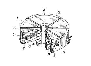
Fig. 1 ls a perspective view of a commutator of the
present invention, in which a part thereof is cut away;
Fig. 2 is a perspective view of a base member of a
conductive carbon element and a metallic plate member, as
constituents of carbon segments and metalllc segments,
which are respectively used for production of the
commutator of Fig. 1;
Fig. 3 is a perspective view showing a condition under
that the plate member is secured to the base member which
is used for production of the commutator of the present
invention; and
Fig. 4 is an enlarged perspective view showing a
fixing surface of a fixing member for the carbon segments
of constituting the commutator of the present invention.
DESCRIPTION OF THE PREFERRED EMBODIMENT
An embodiment of the present invention is now
described with reference to the drawings.
Figure 1 is a perspective view of a commutator of the
present invention, in which a part thereof is cut away to
clarify an inside structure of the commutator. Figure 2 is
a perspective view of a base member of a conductive carbon
element and a metallic plate member in a disassembled
state, as constituents of carbon segments and metallic
segments of the commutator of the invention.
- In an assembled state shown in Fig. 1, carbon segments
1 made of a conductive carbon material, each of which has
a sectorial top face thereof, are arranged in a circular
manner through respective slits 2 so as not to be in
contact with each other. Further, each of the carbon
segments 1 is provided on inner and outer peripheries
thereof with projecting rims 3 which are arranged in the
vicinity of lower ends of the respective peripheries.
Provided under the carbon segments 1 is a metallic
segment 4 which is made of a suitable material, such as
copper or the like. The segment 4 is provided at inner and
2I38~5~
outer peripheral ends thereof with fixing members 5 which
stand upwardly therefrom. The fixing members 5 encroach
into recesses 6 formed in the projecting rims 3,
respectively, so that it is possible to ensure not only an
electrical conductivity between the respective carbon
segments 1 and the metallic segment 4 but fixing of the
carbon segments 1 on the segment 4 in the circumferential,
diametrical and axial directions thereof.
Figure 4 shows a fixing face of the fixing members 5
with the carbon segment 1. In the shown embodiment, a
large number of irregularities are formed on the fixing
face of each fixing member 5 so as to increase an
engagement area thereof with the carbon segment 1.
Furthermore, according to the embodiment, the carbon
segments 1 and the metallic segment 4 are covered inside
of respective inner peripheral ends thereof, outside of
respective outer peripheral ends thereof and underside of
the segment 4 with a non-conductive hub body 7 which is
made of synthetic resin, as shown in Fig. 1. Note that,
the metallic segment 4 includes a plurality of engagement
pieces 8 in order to ensure an integration thereof with
the hub body 7 and further includes a plurality of
connection terminals 9 formed on an outer periphery
thereof.
The commutator of the invention is produced as
follows.
At first, as shown in Fig. 2, a base member 11 of
conductive carbon elements is formed so as to be a
circular plate member having a band of projecting rims 3
integrally formed on inner and outer circumferential
surfaces and in the vicinity of respective lower edges
thereof.
Next, for engagement with the fixing members 5 of the
metallic segment 4, the recesses 6 are regularly formed on
the respective rims 3 by cutting off the rims 3 at
intervals by suitable cutting means.
Note, in another formation of the invention, the
-6-
2138350
recesses 6 and the rims 3 may be slmultaneously formed in
a part by press, at the stage of manufacturing the
circular base member 11 of the conductive carbon elements.
Further, the recesses 6 need not always be formed so as to
have smooth surfaces in comparison with other surfaces of
the base member 11. That is, in case of forming them with
uneven surfaces, an engagement area of the base member 11
would be increased at the stage of engagement with the
fixing members 5, thereby allowing the conductivity and
mechanical integration between the base member 11 and
metallic segment 4 to be progressed.
On the other hand, by a stamp-out processing or the
like, a metallic plate member 12 as a material of the
metallic segment 4 is so formed as to be of a circular
shape and to have the fixing members 5 standing on inner
and outer peripheries thereof corresponding to the
recesses 6, respectively. At this precessing stage, the
above-mentioned engagement pieces 8 are formed around the
inner fixing members 5 and the connection terminals 9 are
formed to project radially outwardly from the outer
periphery of the member 12. Next, after positioning the
respective recesses 6 of the base member 11 in alignment
with the respective fixing members 5 of the plate member
12, the base member 11 is engaged with the plate member 12
by suitable means, such as press-fitting, so that an
assembly as shown in Fig. 3 can be completed.
Thereafter, the non-conductive hub body 7 made of a
suitable material, such as synthetic resin or the like, is
formed integrally with the assembly so as to extend up to
a central portion into which an output shaft of a not-
shown motor is inserted with respect to the inside of the
assembly and to extend around the outside of the assembly
and under the metallic segment 4. In this way, the
integration of the base member 11 with the plate member 12
can be improved, whereby the conductivity therebetween
through the fixing members 5 and the others becomes to be
further favorable. In addltion, since also the engagement
-7-
213~0
pieces 8 of the plate member 12 are surrounded by the
synthetic resin when molding the hub body 7, the plate
member 12 can be fixed to the hub body 7 securely.
Next, the slits 2 are formed in the so-formed
commutator body to extend from a top face of the base
member 11 up to somewhat underside of the plate member 12,
so that the commutator can be completed.
Under condition of bending the connection terminals 9
as shown in figures, since almost contacts between the
carbon segments 1 and the metallic segment 4 are sealed in
the synthetic resin, the stable conductivity can be
maintained over a long term of using. Furthermore, due to
press-fitting of the fixing members 5 etc., the fixing of
the carbon segments 1 to the metallic segment 4 can be
executed easily.
Note that, in the embodiment of the invention, the
fixing members 5 have only to serve to fix the carbon
segments 1 to the metallic segment 4 under condition that
the respective carbon segments 1 are carried between the
fixing members 5 and therefore, it should be understood by
those skilled in the art that the present invention is not
limitative to the afore-mentioned embodiment in terms of
their configuration, number, position of the metallic
segment and so on. Further, also in case of providing
irregularities on back faces of the fixing members 5, any
any irregularities may be applicable in terms of their
configuration, position and size, without departing an aim
of increasing an engagement area of the members 5 with the
carbon segments 1. Although the projecting rims 3 are
formed on both inner and outer peripheries of the carbon
segments 1 like a band, their configuration are not
limitative to those in the shown embodiment.
Finally, it will be understood by those skilled in the
art that the forgoing description of the embodiment of the
disclosed commutator, and that various changes and
modifications may be made to the present invention without
departing from the spirit and scope thereof.
-8-