Note: Descriptions are shown in the official language in which they were submitted.
CA 02138373 2001-10-O1
1V(.) .~).1/1121R f';'1. ~,1 a;/i1(l:f,~
i
BULK PACKAGING SYSTE=M
The present invention relates to the packaging of articles of any kind
particularly flowable granules, powders or liquids.
The method or methods of the invention may be incorporated into fully
automated packaging lines.
The invention is useful in the packaging of flowable granules such as
plastic granules, cereals, powders such as fertilisers or liquids as well as
for
baling of waste materials with only minor modification being required.
Materials of all kinds including industrial, commercial and domestic waste
materials are currently handled in a variety of ways including use of plastic
bags
~r~hict~ are difficult to handle if they are to be subject to exposure to
liquids and/or
compacting of contents and includes intermediate bulk containers which are
usually filled with material such as fertilisers, cereal or plastic granules.
Furthermore such bags tend to be expensive and do not lend themselves to
recycling procedures.
A packaging system of the present type has already been disclosed in
our co-pending International P;~te~t Application No. PCT/AU92/00142.,
The present invention has as its objective to pr~wide a bulk package and
packaging system in which the need for a solid base member or conventional
pallet base is dispensed with and the package can be handled by normal
handling machinery and methods.
There is provided according to the present invention a method of forming
a bulk container comprising the steps of forming an open container of flexible
material having walls and a closed bottom with a retractable or removable
framework therein, at least partially filling the container with material,
removing
or retracting said framework from said container, closing the container, and
subsequently over wrapping the closed container with stretch plastic film to
form
reinforcing strips to reinforce the container and allow engagement with
handling
apparatus such as the fork of a lift truck.
In a further aspect of the present invention there is provided a
method of forming a container comprising the steps of forming an open chamber
WO 94/02358 ~ PCT/AU93/00365
_.
2
of flexible material having walls and a closed bottom with a retractable or
removable framework therein acting to maintain the container volume open, at
least partially' filling the container with material, removing or retracting
said
framework from said container, wrapping said container and a spacer means
with flexible material to reinforce said container and secure said spacer
means,
said spacer means being arranged and adapted to allow engagement with a
load handling apparatus.
A reinforcing stretch film is preferably wrapped circumferentially around
the container end to end to form a right angular cross pattern. To assist
engagement with the fork or forks of a lift truck a rigid spacer members) is
(are)
provided at either end of the container between the end of the container and
the
reinforcing wrap. Thus with the spacer at the top of the container, the
container
can be transported by a lift truck suspended from the tine of the lift truck
or
resting on the tine with the spacers at the bottom of the container.
It has been found that the container formed in accordance with the
invention will assume a substantially rectangular cubic configuration which is
conveniently stackabie in the manner of a conventional rectangular cubic bag
container without danger of the contents of the container slipping or moving.
The invention is conveniently used in association with a packaging
system disclosed in our above-referred to patent application, however, it can
be
utilised with conventional pre-formed plastic bag systems and overcomes the
problem inherent in such systems in retaining a substantially rectangular
cubic
configuration. Furthermore in conventional bag systems fiowable contents such
as liquids or granules do tend to shift and the present invention is adapted
to
overcome this difficulty.
The invention may be used with or without a support base. A support
base is not essential if a rigid spacer is provided at the top or the bottom
of the
bag to accept the fork of lift truck equipment. '
The invention will be described in greater detail with reference to the
accompanying drawings in which:
Figures 1 and 1A are perspective views of a container formed according
to the invention;
PCT/AU93/00365
,_.~.~ W~ 94/02358
3
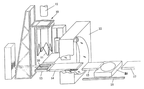
Figure 2 shows schematically a system of formation of a container and
conveyance according to the invention;
Figure 2A is a partial perspective view of the reinforcing wrapping step
according to the present invention.
With reference to Figures 2 and 2A the container is formed at the station
and filled with material and the frame removed in accordance with
procedures as disclosed in our earlier patent application No. PCT/AU92100142
referred to above wherein stretch plastic film is wrapped around a removable
or
retractable frame 11 to form a walled container. The container is preferably
10 solely constructed of the plastic film with the retractable/removable frame
11 and
conveyor 13 being its sole means of support during a filling operation.
The container is formed by wrapping the frame with several layers of
stretch plastic film including over wrapping at the base of the frame 'I 1.
The film
is applied at up to 300% elongation of the film so that the film contracts
inwardly
to form a base that can be easily closed as by tying or welding. In one
embodiment of the invention the frame with its wrapping is then rested on a
conveyor 13 upon which is placed a pair of spacer members 20. At this time the
formed container may be filled with any suitable material but including any
flowable material such as granules, powder or liquid. The size of the
container
is preferably of a standard size of approximately 1000 kilograms. This weight
may be varied according to individual requirements.
After filling the container from filler nozzle 12 the container is self
supporting and the frame is adapted to be removed/retracted from the top of
the
container and the container closed oft at the top. The weight of the container
and contents is sufficient to remain in its rest position on the conveyor 13
whilst
the frame 11 is removed or retracted from the container.
The container may be constituted by a strong plastic bag rather than
formed by stretch plastic film and the bag is supported or held open in its
empty
condition by a removable frame structure which may be in the same form as is
used in the container formed by wrapped film material.
After closing the top of the container 21 the container mounted on spacer
elements 20 is moved on to a conveyor 14 operating in conjunction with a
CA 02138373 2001-10-O1
~;~'1 ) a.;,';y y~~ '''~ '! ' , ~ '..'t.i;
tubular fiirz~ wrapping station 22 which may be of ;t~;~ same gE:nera: type ~.
disclosed in US Patent No. 4079565 in which plas;ic stretch riim is
c;saE~r~s~~-;
from an orbiting stretch film dispenser apparatus.
The stretch film is wrapped first around the container to form a single
band 16 extending end to end around the container over the spacer members
20. The container is then moved on to a turntable 26 and turn through
90° and
returned to the wrapping station 22 wherein the second band 17 is applied to
the container to form the cross-wrapping as best shown in Figure 1 with the
spacer members 20 securely fixed to the bottom of the container.
With specific reference to Figure 2A 'the conveyor 14 is provided with
fixed slide members 24 at each side, preferably coated with anti-friction
material
such as a non-stick coating or suitable lubricant to facilitate sliding of the
reinforcing plastic layer 23 therefrom after a wrapping step forming a
reinforcing
layers 16 and 17 on the container. The space between the conveyors 14,15 is
set at approximately one half of the width of the plastic film 23 so that
approximately one half of the film width is actually contacting the slide
members
24 and the other half is d~rectlv contacting the container wall. After tightly
wrapping the film 23 to the filled container 21 the process is repeated after
rotation of the container 21 through 90°.
The film slides off into the gap between the conveyors 14 and 15 due to
its inherent tightness under tension to closely envelop the container as shown
in
Figures i and 1 A. A container can then be moved to the conveyor 17 for
handling by conventional handling equipment such as a fork lift truck either
by
lifting by insertion of the fork lift tines into the spacer member 20 shown at
Figure
1 or the insertion of the tine into the spacer mE:mber 20a as shown in Figure
1 A.
To achieve movement of the container from the turntable the turntable is
mounted on a hoist (not shown) and is movable on a track 25 relative to
conveyors 15 and 17 to enable transfer of the loaded container from and to the
conveyors 15 and 17 and the turntable. '
With specific reference to Figure 1 A a rigid spacer memoer 20a is
positioned on tap of the filled container and is secured in position shown by
VVO 94/0235i~ ~ ~ ~ ~ ~j ~ 3 PCT/AU93/00365
aver wrapping of the container by the reinforcing strips 16,17 in similar
fashion
to that described previously.
It has been surprisingly found that the wrapping of the container as
shown ensures that the overall configuration of the , container substantially
5 conforms to that of a rectangular cubic construction as shown in Figures 1
and
1A and can be easily stacked in container transport or for any long distance
transport.