Note: Descriptions are shown in the official language in which they were submitted.
~' ' ~i3843~
93-rELT-151
SYNCHRONIZER WITH CONE CUP LOCATOR PINS
Field of the Invention
This invention relates to pin-type synchronizer mechanisms for a
transmission. More specifically, the invention relates to axially retaining a
cone
friction member for such mechanisms.
Background of the Invention
It is well known in the multiple ratio transmission art that
synchronizer mechanisms may be used to reduce shift time of all or some of the
transmission gear ratios. It is also known that the shift effort required by a
vehicle operator, i.e., force applied to a shift lever, may be reduced by use
of
synchronizer mechanisms of the self-energizing type. A prior art example of a
pin-type synchronizer mechanism with self-energization may be seen by
reference to U.S. Patent 5,092,439.
The pin-type synchronizer mechanism disclosed in the above
patent includes friction and jaw members for respectively synchronizing and
positive clutching axially spaced apart gears to a shaft; blockers engaged in
response to a pre-energizer effecting initial engagement of the friction
members
in response to initial engaging movement of one of the jaw members by a shift
force, the blodcers being operative to prevent asynchronous engagement of the
jaw members and to transmit the shift force to the friction members to
increase
synchronizing torque thereof, and self-energizing ramps reacting the torque to
provide an additional force in the direction of and additive to the shift
force for
further increasing the synchronizing torque of the friction members. A pin-
type
synchronizer mechanism employing the invention herein may or may not include
self-energizing ramps.
Many pin-type synchronizer mechanisms include rings having cone
friction surfaces that are axially movable from a neutral position of the
synchronizer mechanism into mating engagement with cone friction surfaces
2~ 38430
defined by members affixed against rotation and all axial movement relative to
the gears.
Such axial affixing of the members is preferred to ensure clearance
between the friction surfaces when the synchronizer mechanism is in neutral,
to
ensure disengagement of the surfaces when the synchronizer mechanism is
moved from an engaged position to neutral position, ensure or mitigate
inadvertent engagement of self-energizing ramps due to, for example, viscous
shear drag of oil between the friction surfaces producing a torque, etc.
In some transmission installations, it is difficult and/or cost
prohibitive to axially affix some of the members to the gears. The invention
disclosed herein negates the need to affix the members against all axial
movement. The invention also ensures the above mentioned clearance,
disengagement and mitigation of viscous shear drag in the event of failure of
other means used to initially axially affix the members to the gears.
Summary of the Invention
This invention improves the functional relation between friction
surfaces of a synchronizer mechanism.
According to a feature of the invention, a pin-type synchronizer
mechanism is selectively operative to frictionally synchronize and positive
connect either of first and second axially spaced apart drives to a shaft. The
drives are mounted for relative rotation about an axis common to the shaft and
secured against axial movement relative to the shaft. Drive jaw means are
affixed to each drive and engageable with axially movable jaw means having
axially extending internal splines slidably mating continuously with axially
extending external splines affixed to the shaft. First and second cone
friction
surfaces are respectively defined by axially spaced apart first and second
members that are respectively secured by attachment means for fixed rotation
with the first and second drives and for limited axial movement away from the
2138430
-3-
space between the gears. Third and fourth cone friction surfaces are defined
by a pair of axially spaced apart rings disposed concentric to the shaft means
and axially movable between the spaced apart drives for axial movement into
engagement respectively with the first and second friction surfaces to
synchronize the drives with the shaft. A flange extends radially between the
rings for axially moving the movable rings and jaw means into the engagement
in response to an axially bi-directional shift force (Fo) applied to the
flange.
Means are provided to secure the flange against axial movement relative to the
axially movable jaw means. Blocker means prevent engagement of the jaw
means prior to the synchronizing. The blocker means include a plurality of
circumferentially spaced apart and axially extending pins which rigidly secure
the rings together. The pins extend through openings in the flange. Each pin
has axially spaced apart blocker shoulders that are engageable with blocker
shoulders defined on opposite sides of the flange and about the associated
openings. Pre-energizers are for engaging either one of the third and fourth
friction surfaces respectively with the first and second friction surfaces in
response to initial axial movement of the flange by the shift force from a
neutral
position toward one of the drives, for engaging the blocker means in response
to engagement of the friction surfaces producing a synchronizing torque
transmitted to the flange via the pins, and for transmitting the shift force
to the
engaged friction surfaces via the engaged blocker means to increase the
engaging force of the engaged friction surfaces.
The invention is characterized by: the attachment means allowing
axial movement of the first and second friction members in a direction toward
the
friction rings, and a plurality of circumferentially spaced apart rigid
members are
axially interposed between the first and second members for limiting or
arresting
axial movement toward the friction rings.
Brief Description of the Drawings
2138430
~-
The synchronizer mechanism of the invention is shown in the
accompanying drawings in which:
Figure 1 is a sectional view of a double-acting synchronizer
mechanism looking along line 1-1 of Figure 2;
Figure 2 is a partially sectioned view of the mechanism looking
along line 2-2 of Figure 1;
Figure 3 is a sectional view of a portion of the mechanism looking
along line 3-3 of Figure 1;
Figure 4 is a perspective view of a component in Figures 1 and 2;
Figures 5 and 6 are detailed views of a plunger component and a
pin component in Figures 1 and 2;
Figure 7 is a partial view of the mechanism in Figure 1 with a jaw
clutch thereof in an engaged position;
Figures 8 and 9 are sectional views of toothed portions of the
mechanism looking along line 8-8 of Figure 1;
Figure 10 is a graphical representation of axial forces and torques
acting on a shift flange of the synchronizer; and
Figure 11 is an enlarged view of an alternative embodiment of a
portion of the synchronizer mechanism.
Detailed Description of the Drawings
The term "synchronizer clutch mechanism" shall designate a clutch
mechanism utilized to non-rotatably couple a selected ratio gear to a shaft by
means of a positive clutch in which attempted engagement of the positive
clutch
is prevented until members of the positive clutch are brought to substantially
synchronous rotation by a synchronizing friction clutch associated with the
positive clutch. The term "self-energizing" shall designate a synchronizer
clutch
mechanism which includes ramps or cams or the like to increase the engaging
.v ~ ~~3g43o
_5_
force of the synchronizing clutch in proportion to the synchronizing torque of
the
friction clutch.
Looking first mainly at Figures 1 and 2, therein is shown a gear
and synchronizer assembly 10 for an otherwise unshown transmission of the
type intended for use in a land vehicle, particularly of the type used in
heavy
duty trucks. However, assembly 10 may be used in other applications. The
assembly includes a transmission input shaft 11 and a main shaft 12 mounted
for rotation about a generally common axes 11 a and 12a, spaced apart ratio
gears 14,16 rotatably supported on the shaft and secured against axial
movement relative to the shaft by annular thrust members affixed to the shaft
in
known manner, and a double-acting pin-type synchronizer clutch mechanism 18.
When assembly 10 is part of a twin countershaft transmission, such as
disclosed
in U.S. Patent Nos. 3,648,546 and 4,788,889, teeth 14a on gear 14 will be in
constant mesh with gears on unshown countershafts driven by gear 16, shaft 12
will be connected to or selectively connectable to a load, and shaft 12 will
be free
to move somewhat radially as is well known in the prior art. Gear 16 is
splined to
input shaft 11 and teeth 16a are in constant mesh with teeth of gears on the
unshown countershafts.
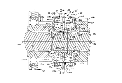
The synchronizer mechanism 18 includes annular friction members
or cone cups 20,22 and annular jaw clutch members 14b,16b secured for
rotation with gears 14,16, jaw clutch members 24,26 having internal spline
teeth
24a,26a slidably mating with external spline teeth 12b integrally formed with
the
shaft or otherwise affixed thereto, a radially extending shift flange 28,
having
axially oppositely facing sides 28a,28b sandwiched between axially facing
surfaces 24b,26b of the jaw members 24,26, three H-shaped retainer members
(one of which is shown in perspective in Figure 4) for securing the flange and
jaw members against relative axial movement, annular friction members or rings
32,34 rigidly secured together by three circumferentially spaced apart pins 36
~~~8~3~
extending axially from each of the friction members and through openings 28c
in the flange, and three pre-energizer assemblies 38 each including a spring
40
and a plunger 42 which reacts with surfaces defined by the pins. The number
of retainers 30, pins 36 and assemblies 38 may be more or less than disclosed
herein.
Shaft 11, gear 16 and a bearing 17 are preferably installed as an
assembly through a bearing race support opening 19a in a partially shown
housing wall 19 of the transmission. Since the diameter of friction member 22
is greater than the diameter of opening 19a, member 22 is installed on gear 16
after the assembly is installed.
Friction members 20,22 have internal cone friction surfaces
20a,22a which respectively mate with external cone friction surfaces 32a,34a
of
annular friction members 32,34. As is readily seen, friction members 20,32 and
22,34 pair up to define friction clutches for synchronizing the gears to the
shaft
prior to engagement of the jaw clutches. Friction members 20,22 include
internal splines 20b,22b which slidably mate with external splines 14c,16c
defined by gears 14,16 for preventing relative rotation therebetween. Abutment
or reaction surfaces 14d,16d defined by gears 14,16 limit axial movement of
members 20,22 away from the space between the gears. Axial movement of
members toward the space between the gears is limited or prevented by a
plurality of rigid, elongated members 44 slidably extending through axially
aligned openings 32b,34b in members 32,34 and openings 28c in flange 28. A
spring clip or an elastic band 46, such as an o-ring griping member 44, may be
used to retain each member 44 in position prior to installation of members
32,34
between members 20,22. Members 44 also ensure disengagement of the cone
surfaces when either of the movable jaw members 24,26 is moved from an
engaged position to the neutral position.
A wide range of cone angles may be used; cone angles of seven
and one-half degrees are employed herein. The friction surfaces may be
~~~~~~0
-7-
defined by any of several known friction materials affixed to the base member;
herein, pyrolytic carbon friction materials, such as disclosed in U.S. Patents
4,700,823; 4,844,218; and 4,778,548 are preferred.
Pins 36 are shown in greater detail in Figure 6. Each pin includes
major diameter portions 36a having diameters slightly less than the diameter
of
flange openings 28c, a reduced diameter or groove portion 36b spaced between
friction rings 32,34 (herein midway), conical blocker shoulders or surfaces
36c,36d extending radially outward from the pin axis and axially away from
each
other at angles herein of about forty degrees relative to a line normal to the
pin
axis, and preferably, but not necessarily, independent pre-energizer surfaces
36e,36f and extended secondary centering surfaces 36g,36h. The grooved
portions, when disposed within their respective flange openings, allow limited
rotation of the rigid friction ring and pin assembly relative to the flange to
effect
engagement of the pin blocker shoulders with chamfered blocker shoulders
28e,28f defined about the flange openings. The pre-energizer surfaces 36e,36f
chordally intersect or remove a portion of conical blocker shoulders 36c,36d,
are
preferably (but not necessarily) flat planar surfaces and form angles relative
to
the pin axis which are somewhat less than the angles of the blocker surfaces.
Centering surfaces 36g,36h are also flat planar surfaces and, as is readily
apparent in the drawings, form angles relative to the pin axis which are
substantially less than the angles of the blocker and pre-energizer surfaces.
As
disclosed herein, the chordal extents of the flat surfaces are tangent to
circles
concentric to the pin axis and the shaft axis. Alternatively, surfaces 36e-36f
may
be dispensed with, pre-energizer plunders 124 then react against blocker
surfaces 36c,36d.
The helical compression springs 40 disposed in slots 28g of the
flange bias plungers 42 radially outward toward the pin pre-energizer
surfaces.
The major extent of the slots preferably extends radially relative to the
shaft axis.
~~~s~3o
The slots also extend axially through the flange sides 28a,28b, into flange
openings 28c, and have ends 28h at their radially inward extent for the
springs
to react against.
As previously mentioned, jaw members 24,26 include internal
spline teeth 24a,26a slidably mating with external spline teeth 12b affixed to
the
shaft. The external splines have involute flank surfaces 12c extending
parallel
to the shaft axis, and the mating thereof with flank surfaces of the jaw
member
splines prevents relative rotation therebetween. H-shaped members 30 each
include end portions 30a,30b, which react against jaw member surfaces 24c,26c,
and a center portion 30c which interconnects the end portions. The center
portion extends snugly through axially extending slots 24d,26d in the jaw
members and freely through openings 28k having radially extending stop
surfaces 28n,28m which cooperate with center portion 30c to limit rotational
movement of the flange relative to the jaw members and shaft for reasons
explained hereinafter.
As best seen in Figures 1-2 and 7-10, portions of some of the
external teeth 12b of the shaft in both axial directions from the Figures 1, 2
and
8 neutral position of flange 28 are modified to provide one or more ramp
surfaces which cooperate with a like number of ramp surfaces defined by
reaction means or internal teeth 48 extending radially inward from flange 28
and
into the axially extending spaces between shaft splines 12b. The ramp surfaces
allow limited rotation of the flange relative to jaw members 24,26 and shaft
12,
and react synchronizing torque between the cone clutches and shaft to provide
an additive axial self-energizing force for increasing the engaging force of
the
cone clutch initially engaged by a shift force applied to flange 28, thereby
increasing the synchronizing torque provided by the cone clutch. Ramp
surfaces may be provided for increasing synchronizing force for one or both
gears and/or for increasing synchronizing force in response to torque in
either
direction, as is encountered for up and down shifts. More specifically, each
2138430
_g_
tooth 12b, circumferentially between each H-shaped retainer center portion
30c,
has first and second axially spaced apart recesses defining annular grooves
having first ends defined by post-like portions 50, axially opposite ends
12d,12e,
and minimum outside diameters 12f. The minimum outside diameters 12f are
greater than the root diameter of splines 12b and greater than the inside
diameters 24c,26c of the jaw clutch splines 24a,26a. Also, the minimum outside
diameters 12f are less than the inside of the flange internal teeth 48. The
post-
like portions 50 have a diamond-shape, formed by removing portions of each
tooth in both axial directions therefrom. The axial and radial extend of the
removed portions are selected to facilitate ease of machining boost ramp
surfaces 50a,50b,50c,50d on post portion 50 and to minimize the effects such
removal has relative to the strength of the teeth 12b. Further, spline teeth
12b
are provided with sufficient radial depth to ensure that the ramp surfaces
have
enough surface area to minimize wear due to forces acting thereon. The axial
extent of the removed portions or recesses between axial ends 50a,50b of post
portions 50 and axial ends 12d,12e of teeth 12 are formed by simply machining
annular grooves in the teeth. The axial length of the removed portions is
sufficient to facilitate insertion of a machining tool to form the ramp
surfaces.
Ramp surfaces 50a,50b respectively react against ramp surfaces 48a,48b on
flange teeth 48 to provide the additive axial forces (Fa) to increase or
assist the
synchronization rate of gear 14 in response to torque in either direction.
Ramp
surfaces 50c,50d respectively react against ramp surfaces 48c,48d to provide
the additive axial forces (Fa) for gear 16 in response to synchronizing torque
in
either direction. The angles of the ramp surfaces may be varied to provide
different amounts of additive axial force for up and down shifts and for high
and
low speed ratios. Also, if no additive axial force is preferred in one
direction for
one gear or more, the ramp surfaces may be parallel to the spline, i.e., no
effective ramp surfaces are provided. The magnitude or amount of the axial
additive forces, as explained further hereinafter, is also a function of the
mean
' ,
-10-
radii ratio of friction clutches and self-energizing ramps. Accordingly, the
magnitude of the additive forces for a given shift force applied to shift
flange 28
by a shift fork may be varied by varying the ramp angles and/or the mean radii
ratio. Internal teeth 48 and post-like portions 50 may be provided with non-
boost
surfaces or flats 48e and 50e on circumferentially opposite sides thereof. The
non-boost surfaces react against each other while flange 28 is-in the neutral
position to prevent activation of the self-energizing ramps in the event
either of
the cone clutches produce a torque due to, for example, viscous shear of oil
between the friction surfaces.
With reference to Figures 1 and 8, when the flange 28 is in the
neutral position, reduced diameter portions 36b of pins 36 are radially
aligned
with their associated flange openings 28c, friction surtaces of the cone
clutches
are slightly spaced apart and are maintained in this spaced relation by angled
pre-energizer surfaces 42a,42b of the plungers 42 acting on pre-energizer
surfaces 36e,36f of pins 36 by the force of springs 40 and by ends 44a,44b of
elongated members 44 abutting friction members 20,22. When it is desired to
couple either gear to the shaft, an appropriate and unshown shift mechanism,
such as disclosed in U.S. Patent 4,920,815, connected to the outer periphery
of
flange 28 in known manner for
moving the flange axially along the axis of shaft 12 either left to couple
gear 16
or right to couple gear 14. The shift mechanism may be manually moved by an
operator through a linkage system, may be selectively moved by an actuator, or
may be moved by means which automatically initiate shift mechanism movement
and which also controls the magnitude of the force applied by the shift
mechanism. When the shift mechanism is manually moved, the force is
proportional to the force applied by the operator to a shift lever. Whether
manually or automatically applied, the force is applied to flange 28 in an
axial
direction and is represented by the length of arrow Fo in Figure 10.
~~~8~.~C~
-11-
Initial rightward axial movement of flange 28 by the operator shift
force Fo is transmitted by pre-energizer plungers 42 to the pins by pre-
energizer
surfaces 36f to effect initial frictional engagement of cone surface 32a with
cone
surface 20a. The initial engagement force of the cone surfaces is, of course,
a
function of the force of springs 40 and the angles of the pre-energizer
surfaces.
The initial frictional engagement (provided an asynchronous condition exists
and
momentarily ignoring the effect of the self-energizing ramps) produces an
initial
cone clutch engaging force and synchronizing torque To which ensures limited
relative rotation between flange 28 and the engaged friction ring, and hence,
movement of the reduced diameter pin portions 36b to the appropriate sides of
the flange openings 28c to provide engagement of pin blocker shoulders 36c
with flange blocker shoulders 28e. When the blocker shoulders are engaged,
the full operator shift force Fo on flange 28 is transmitted to friction ring
32 via
the blocker shoulders, whereby the cone clutch is engaged by the full force of
the operator shift force Fo to provide a resultant operator synchronizing
torque
To. This operator synchronizing torque To is represented by arrow To in Figure
10. Since the blocker shoulders are disposed at angles relative to the axial
direction of operator shift force Fo, they produce a counter force or
unblocking
torque which is counter to the synchronizing torque from the cone clutch but
of
lesser magnitude during asynchronous conditions. As substantial synchronism
is reached, the synchronizing torque drops below the unblocking torque,
whereby the blocker shoulders move the pins into concentric relation with
openings 28c to allow continued axial movement of the flange and engagement
of the external jaw teeth 24d of jaw member 24 with internal jaw teeth 14b of
gear 14, as shown in Figure 7. As is known in the prior art and as is
specified
by reference numbers only for jaw teeth 16b in Figure 7, the lead portions of
the
jaw teeth have rake leading edges 16c to reduce tooth damage during initial
contact, and have chamfer or wedge faces 16d to clock the teeth into mating
alignment. Jaw teeth with such lead portions are disclosed in greater detail
in
-12- 21 3 8 4 3 4
U.S. Patent 4,246,993 along with U.S.
Patent 3,265,173 which provides a teaching for the proper rake angles. The
wedge faces, which may be asymmetric, prevent delay of shift completion due
to abutting contact of the leading edges of the teeth. To facilitate smooth
and
relatively effortless completion of shifts, the jaw teeth are preferably as
fine or
small, as practicable, in the circumferential direction, thereby minimizing
the
number or rotational clocking degrees necessary to matingly align the jaw
teeth.
Also, the jaw teeth are preferably disposed about as large a diameter as is
practicable.
Still ignoring the effects of the self-energizing ramps, cone clutch
torque provided by the force Fa is expressed by the following equation:
To = FoR~N~ sina
where:
R~ - the mean radius of the cone friction surface,
N~ - the coefficient of friction of the cone friction surface, and
a - the angle of the cone friction surfaces.
Looking now at the affects of the self-energizing ramps and
referring particularly to Figures 8 and 9, the synchronizing torque To due to
the
operator applied axial shift force Fo is, of course, transmitted to flange 28
by pins
36 and is reacted to shaft 12 across the self-energizing ramp surfaces. The
self-energizing ramp surfaces, when engaged, limit rotation of the flange
relative
to shaft 12 and jaw members 24,26 and produce an axial force component or
axial additive force Fa acting on the flange in the same direction as shift
force Fo,
thereby further increasing the engaging force of the cone clutch to provide an
additive synchronizing torque Ta which adds to the torque To. Figure 8
illustrates
the position of the self-energizing ramp surtaces and the position of the jaw
member splines 24a,26a to the shaft splines 12b while shift flange 28 is in
tha
neutral position corresponding to the position of Figure 1. Figure 9
illustrates
~~~8~30
-13-
a position of the ramps and splines while gear 14 is being synchronized by
engaged cone surfaces 32a,20a. The engaged cone surfaces are producing a
synchronizing torque in a direction which has effected engagement of flange
member ramp surfaces 48a with shaft ramp surfaces 50a. Hence, the sum of the
axial forces for engaging the cone clutch are Fo plus Fa and the sum of the
synchronizing torques being produced by the cone clutch are To plus Ta, as
graphically shown in Figure 10. For a given operator shift force Fo and an
operator synchronizing torque To, the magnitude of the axial additive force is
preferably a function of the angle of the engaged self-energizing ramp
surfaces.
This angle is preferably great enough to produce an additive force Fa of
magnitude sufficient to significantly increase synchronizing torque and
decrease
synchronizing time in response to a given moderate shift effort by the
operator.
However, this angle is also preferably low enough to produce a controlled
axial
additive force Fa, i.e., the force Fa should increase or decrease in response
to
the force Fo increasing or decreasing. If the ramp angle is too great, the
ramps
are self-locking rather than self-energizing; hence, once initial engagement
of
the cone clutch is effected, the force Fa will rapidly and uncontrollably
increase
independent of the force Fa, thereby driving the cone clutch toward lockup.
Self-
locking rather than self-energizing decreases shift quality or shift feel, may
over
stress synchronizer components, may cause over heating and rapid wear of the
cone clutch surfaces, and may even override operator movement of the shift
lever.
The main variables for calculating self-energizing ramp angles for
providing additive axial forces Fa, which increase or decrease in proportion
to
operator forces Fo, are cone clutch angle, cone clutch coefficient of
friction,
mean radii ratio of the cone clutch and of the self-energizing ramps, ramp
coefficient of friction, and pressure angle of the self-energizing ramps. The
pressure angle may be zero. Herein, the ramps have a pressure angle of 20
degrees. Further details for calculating and controlling self-energizing or
boost
21 384 30
-14-
forces may be obtained by reference to U.S. Patent 5,092,439.
Figure 11 illustrates an alternative embodiment of the elongated
member 44. In the alternative embodiment each elongated member is
designated 114 and is modified at its ends 114a, 114b to include antifriction
means 114c, 114d to reduce drag between the ends and cone cups 20, 22.
Such drag is detrimental to shift performance, and may cause failures due to
wear and heat generation where the ends contact the come cups. Herein, the
antifriction means 114c, 114d are each a ball bearing retained in a pocket in
the
ends 114a, 114b. Lubrication between each pocket and ball may be provided
by impregnating each pocket with a lubricant in known manner or by splash of
transmission oil on the exposed portions of the ball.
Two embodiments of a synchronizer mechanism with self
energizing and with improved neutral positioning has been disclosed. Many
variations and modifications of the embodiments are believed to be within the
spirit of the invention. The following claims are intended to cover the
inventive
portions of disclosed mechanism and variations and modifications believed to
be within the spirit of the invention.