Language selection

Search

Patent 2138597 Summary

Third-party information liability

Some of the information on this Web page has been provided by external sources. The Government of Canada is not responsible for the accuracy, reliability or currency of the information supplied by external sources. Users wishing to rely upon this information should consult directly with the source of the information. Content provided by external sources is not subject to official languages, privacy and accessibility requirements.

Claims and Abstract availability

Any discrepancies in the text and image of the Claims and Abstract are due to differing posting times. Text of the Claims and Abstract are posted:

  • At the time the application is open to public inspection;
  • At the time of issue of the patent (grant).
(12) Patent: (11) CA 2138597
(54) English Title: HF SHIELDED ELECTRICAL ENCLOSURES
(54) French Title: BOITIER BLINDE CONTRE LE RAYONNEMENT HF POUR MATERIEL ELECTRIQUE
Status: Term Expired - Post Grant Beyond Limit
Bibliographic Data
(51) International Patent Classification (IPC):
  • H05K 09/00 (2006.01)
  • H05K 05/00 (2006.01)
(72) Inventors :
  • ROSE, FRIEDHELM (Germany)
(73) Owners :
  • ROLEC GEHAUSE-SYSTEME GMBH
(71) Applicants :
  • ROLEC GEHAUSE-SYSTEME GMBH (Germany)
(74) Agent: NORTON ROSE FULBRIGHT CANADA LLP/S.E.N.C.R.L., S.R.L.
(74) Associate agent:
(45) Issued: 2005-10-25
(22) Filed Date: 1994-12-20
(41) Open to Public Inspection: 1995-08-22
Examination requested: 2001-12-10
Availability of licence: N/A
Dedicated to the Public: N/A
(25) Language of filing: English

Patent Cooperation Treaty (PCT): No

(30) Application Priority Data:
Application No. Country/Territory Date
08/258,452 (United States of America) 1994-06-10
P 44 05 408.4 (Germany) 1994-02-21

Abstracts

English Abstract

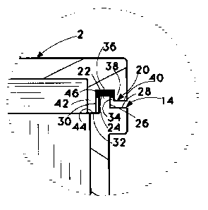
An improved HF shielding feature is provided for electrical enclosures having a box-like base and a sealing cover wherein a tongue projects integrally from the upper periphery of the base into a groove formed integrally in under periphery of the cover. The tongue has a compression surface spaced apart from the base periphery, a first outside wall depends from such tongue compression surface to an outside portion of the base periphery and a first inside wall depends from the tongue compression surface to an inside portion of the base periphery. The groove has a second compression surface spaced apart from the tongue compression surface, a second outside wall depends from the groove compression surface to an outside section of the cover periphery and a second inside wall depends from the groove compression surface to an inside section of the cover periphery. A gasket is compressed between the tongue and groove compression surfaces, the inside wall of the groove is in contact with the inside portion of the base periphery and the groove outside wall is out of contact with any of the outside portion of the base periphery.


French Abstract

L'invention concerne un blindage HF amélioré pour les boîtiers électriques ayant une base de type caisson et un couvercle d'étanchéité, une languette faisant saillie d'un seul tenant de la périphérie supérieure de la base pour s'insérer dans une rainure faisant partie intégrante de la périphérie inférieure du couvercle. La languette possède une surface de compression distante de la périphérie de la base, une première paroi extérieure s'étend de cette surface de compression de la languette jusqu'à une partie extérieure de la périphérie de la base et une première paroi intérieure s'étend de la surface de compression de la languette jusqu'à une partie intérieure de la périphérie de la base. La rainure possède une seconde surface de compression distante de la surface de compression de la languette, une seconde paroi extérieure s'étend de cette surface de compression de la rainure jusqu'à une section extérieure de la périphérie du couvercle et une seconde paroi intérieure s'étend de la surface de compression de la rainure jusqu'à une section intérieure de la périphérie du couvercle. Un joint est comprimé entre les surfaces de compression de la languette et de la rainure, la paroi intérieure de la rainure est en contact avec la partie intérieure de la périphérie de la base et la paroi extérieure de la rainure n'est en contact avec aucune des parties extérieures de la périphérie de la base.

Claims

Note: Claims are shown in the official language in which they were submitted.


CLAIMS,
1. In an electrical enclosure having a box base
including a bottom and a plurality of sides normal to said
bottom joined at corners, the top ends of said sides and
corners defining a base periphery, a sealing cover with sides
and corners that mimic said sides and corners of said base
defining a cover periphery and fasteners to attach said cover
to said base part, an improved HF shielding feature which
comprises:
a tongue projecting vertically from said base
periphery defined by
a top surface spaced apart from said base
periphery,
a tongue outside wall that depends to an
outside portion of said base periphery and
a tongue inside wall that depends to an inside
portion of said base periphery,
a groove formed integrally in said cover
periphery defined by
a compression surface opposing from a
predetermined distance said top surface,
a groove outside wall depending from said
compression surface to an outside section of said cover
periphery, and
a groove inside wall depending from said
compression surface to an inside section of said cover
periphery, and
a gasket compressed between said top surface and
said compression surface,
at least part of said groove inside wall being in
contact with at least part of said inside portion of said base
periphery and all of said groove outside wall being out of
contact with said outside portion of said base periphery.

2. In an electrical enclosure having a box base part
including a bottom and a plurality of sides normal to said
bottom joined at corners, said sides and corners defining a
first periphery, a sealing cover with sides and corners that
mimic to said sides and corners of said base part defining a
second periphery and fasteners to attach said cover to said
base part, an improved HF shielding feature which comprises:
a tongue projecting integrally from said first
periphery normal to said bottom defined by
a first compression surface spaced apart from
said first periphery,
a first outside wall depending from said first
compression surface to an outside portion of said first
periphery and
a first inside wall depending from said first
compression surface to an inside portion of said first
periphery,
a groove formed integrally in said second periphery
defined by
a second compression surface opposing from a
predetermined distance said first compression surface,
a second outside wall depending from said
second compression surface to an outside section of said
second periphery and
a second inside wall depending from said second
compression surface to an inside section of said second
periphery, and
a gasket compressed between said first compression
surface and said second compression surface,
said at least a part of second inside wall is in
contact with at least some of said inside portion of said
first periphery and all of said second outside wall is out of
contact with said outside portion of said first periphery.
-9-

3. The electrical enclosure of claim 2 wherein at least
some of said corners are filleted.
4. The electrical enclosure of claim 2 wherein said
first inside wall is longer in length than said first outside
wall.
5. The electrical enclosure of claim 2 wherein said
second inside wall is longer in length than said second
outside wall.
6. The electrical enclosure of claim 2 wherein said
first compression surface is flat.
7. The electrical enclosure of claim 2 wherein said
second compression surface is flat.
8. The electrical enclosure of claim 6 wherein said
second compression surface is flat.
9. The electrical enclosure of claim 2 wherein said
outside and inside portions of said first periphery are flat.
10. The electrical enclosure of claim 2 wherein said
outside and inside sections of said second periphery are flat.
11. The electrical enclosure of claim 2 wherein said
second inside wall includes projections for contact with said
inside portion of said first periphery.
12. In an electrical enclosure having a box base part
including a bottom and a plurality of sides normal to said
bottom joined at corners, said sides and corners defining a
first periphery, a sealing cover with sides and corners that
mimic to said sides and corners of said base part defining a
-10-

second periphery and fasteners to attach said cover to said
base part, an improved HF shielding feature which comprises:
a tongue projecting integrally from said first
periphery normal to said bottom defined by
a first compression surface spaced apart from
said first periphery,
a first outside wall depending from said first
compression surface to an outside portion of said first
periphery and
a first inside wall longer in length than said
first outside wall depending from said first compression
surface to an inside portion of said first periphery, a groove
formed integrally in said second periphery defined by
a second compression surface opposing from a
predetermined distance said first compression surface,
a second outside wall depending from said
second compression surface to an outside section of said
second periphery and
a second inside wall longer in length than said
second outside wall depending from said second compression
surface to an inside section of said second periphery, and
a gasket compressed between said first compression
surface and said second compression surface,
said second inside wall is at least in part in
contact with said inside portion of said first periphery and
said second outside wall is entirely out of contact with said
outside portion of said first periphery.
-11-

Description

Note: Descriptions are shown in the official language in which they were submitted.


CA 02138597 2005-O1-24
BACKGROUND OF THE INVENTION
1. Field of the Invention
This application relates to electrical enclosures.
More particularly, it concerns such HF (high frequency)
shielded metal electrical enclosures for assembling with
electronic components.
2. Description of the Prior Art
Electrical enclosures for assembling with electronic
components typically consist of an enclosure bottom and a lid.
io The enclosure bottom usually is designed with 2 to 4 mounting
holes for the enclosure itself outside of the enclosure
interior and also has 2 to 6 threads for fastening the lid to
the bottom, e.g., see U.S Patent No. 4,632,269, issued
December 30, 1986.
i5 The lids of these electrical enclosures have to be
closed by screws or quick fasteners to make sure that no dust,
humidity, oil and water can enter the enclosure interior. For
this, the enclosure bottom typically has a tongue and the lid
has a groove and the groove takes a gasket of rubber or
2o plastic. After assembling, the tongue presses against the
gasket to seal the enclosure lid to the bottom.
Because more and more microelectronic components are
used in all kind of industrial fields there is a big risk they
will influence and disturb each other. The designer has to
25 take care, to protect his products from being influenced by
other components or against disturbing other electronic
components with his own product. This interference problem is
of such importance and magnitude that governmental regulations
are in effect or pending relating thereto.
3o The manufacturers of electrical enclosures are well
aware of the need for HF shielding and a variety of schemes
have been developed, both for metal and plastic enclosures,
for providing such articles of manufacture with HF shielding
properties, e.g., see U.S. Patents 2,317,813, issued April 27,
35 1943; 3,534,146, issued October 13, 1970; 4,155,478, issued
- 2 -

CA 02138597 2005-O1-24
May 22, 1979; 4,964,081, issued October 16, 1990 and
5,095,177, issued May 23, 1994.
Aluminium enclosures of standard design give some
protection against HF interferences with enclosed components
s because of the nature of metal, but no normally used plastic
material has any shielding ability. In many cases, parti-
cularly with high frequency radiations, enclosures made of
aluminium metal can provide adequate HF shielding. With lower
frequency radiations, HF shielding becomes a more serious
to problem. For example, conventional groove and tongue sealing
- 2a -

1 structures have to be free of paint and expensive contacting gaskets have to
be
2 installed.
3 An apparent way to enhance the shielding capability of enclosures is to
create
4 paint-free contact areas, but this succeeds only when the contact areas are
protected
against corrosion. Otherwise, the contact areas will after a short time
corrode and the
6 HF screening effect is lost.
7 With prior known electrical enclosures, the contact between the lid and the
8 bottom can be made only on the outer areas of the enclosure, i.e., only in
the outer
9 areas is the contact metal to metal, but this area is not protected against
corrosion. It
is also very costly, to hold this area free of paint, but the majority of
elecrical
11 enclosure users want them painted on the outside for corrosion-protection
and for
12 decorative reasons. Because of this, the use of costly contacting gaskets
and paint-
13 free tongues and grooves has been the only effective method available, but
even with
14 this solution, corrosion problems exist.
The present invention provides new improved forms of HF shielding electrical
16 enclosures that address and mitigate the problems discussed above
associated with
17 related electrical enclosures available heretofore.
18 OBJECTS
19 A principal object of the invention is the provision of HF (high frequency)
shielded metal electrical enclosures for assembling with electronic components
of
21 improved construction as compared with prior known of such type.
22 Further objects included the provision of:
23 1. New metal electrical enclosures provided with a HF shielding that
24 enables the outside thereof to be painted without costly precautions
against damage to
such shielding feature.
26 2. Such new electrical enclosures that eliminate need for use of costly
27 contacting gaskets and paint-free tongues and grooves.
28 3. Such new electrical enclosures that are effectively free of corrosion
29 damage to the HF shielding feature.
Other objects and further scope of applicability of the present invention will
31 become apparent from the detailed descriptions given herein; it should be
understood,
32 however, that the detailed descriptions, while indicating preferred
embodiments of the
-3-

1 invention, are given by way of illustration only, since various changes and
2 modifications within the spirit and scope of the invention will become
apparent from
3 such descriptions.
4 SUMMARY OF THE INVENTION
The objects are accomplished in accordance with the invention by the
6 provision of a improved design in electrical enclosures that have (a) a box-
like base
7 part including a bottom and a plurality of sides normal to the bottom joined
at corners
8 with the sides and corners defining a first periphery, (b) a sealing cover
with sides
9 and corners that mimic to the sides and corners of the base part defining a
second
periphery and (c) fasteners to attach the cover to the base part.
11 The invention provides such electrical enclosures with a highly effective
HF
12 shielding feature by a unique construction of the junction between the base
part and
13 sealing cover. This comprises providing the base part with a tongue
projecting
14 integrally from the first periphery normal to the bottom defined by a first
compression
surface spaced apart from the first periphery, a first outside wall depending
from the
16 first compression surface to an outside portion of the first periphery and
a first inside
17 wall depending from the first compression surface to an inside portion of
the first
18 periphery.
19 The sealing cover has a groove formed integrally in the second periphery
defined by a second compression surface opposing from a predetermined distance
the
21 first compression surface, a second outside wall depending from the second
22 compression surface to an outside section of the second periphery and a
second inside
23 wall depending from the second compression surface to an inside section of
the
24 second periphery.
A gasket is compressed between the first and the second compression surfaces
26 and the second inside wall is at least in part in contact with the inside
portion of the
2 7 first periphery while the second outside wall is entirely out of contact
with the outside
28 portion of the first periphery. Hence, the second inside wall that depends
from the
29 sealing cover is in electrical contact with the inside portion of the base
part and by
adjusting the depth of the second inside wall and the spacing to the first and
second
31 compression surfaces, a desired compression of the gasket can be obtained.
Because
32 such contact areas are inside the enclosure behind the gasket, they are
protected
-4-

~~~8~9~
1 against corrosion.
2 The enclosure base part and sealing cover can be painted or powder coated
3 while they are closed. Because of the space between the outside portion of
the first
4 periphery and the outside section of the second periphery, the base part and
the
sealing cover will not bake together and the interior of the enclosure will be
free of
6 paint. Hence, the new electrical enclosures of the invention attain cost
saving and
7 quality advantage.
8 Excellent electrical contact between the base part and the cover is provided
by
9 the construction of the invention without need to install costly contacting
gaskets. To
improve further the contacting between base part and cover, the second inside
wall
11 may be provided with special contact points instead of a flat contact
surface.
12 In preferred embodiments, a rim may be provided adjacent the junction
13 between the base part and the cover which can serve as a holding frame for
installing
14 the new enclosures in switchboards or cabinet doors.
BRIEF DESCRIPTION OF THE DRAWINGS
16 A more complete understanding of the invention can be obtained by reference
17 to the accompanying drawings in which:
18 FIG. 1 is an isometric view of a HF shielded metal electrical enclosure
19 constructed in accordance with the invention.
FIG. 2 is a lateral, cross-sectional view taken on the line II-II of FIG. 1.
21 FIG. 3 is an enlarged view of the new shielding feature of the invention
shown
22 as the area designated by the circle III on FIG. 2.
23 FIG. 4 is an enlarged view of a second embodiment of the shielding feature
of
24 the invention.
FIG. 5 is an enlarged view of a third embodiment of the shielding feature of
26 the invention.
27 DESCRIPTION OF THE PREFERRED EMBODIMENTS
28 The electrical enclosure 2 of the invention comprises a box-like base part
4
29 and a sealing cover 6.
The part 4 includes a bottom 8 and a plurality of sides 10 normal to said
31 bottom 8 joined at corners 12 that define a first periphery 14.
32 The sides 16 and corners 18 of the cover 6 mimic the sides 10 and corners
12
-5-

CA 02138597 2005-O1-24
of the base part 4 and define a second periphery 20.
Fasteners 22 attach the cover 6 to the base part 4.
The improved HF shielding feature of the invention
shown in FIG. 3 comprises a tongue 22 projecting integrally
from the periphery 14 normal to bottom 8 and is defined by a
first compression surface 24, a first outside wall 26
depending to outside portion 28 of periphery 14 and a first
inside wall 30 depending to inside portion 32 of periphery 14.
A groove 34 is formed integrally in periphery 20 and
io is defined by a second compression surface 36, separated a
predetermined distance from compression surface 24, a second
outside wall 38 depending from compression surface 36 to an
outside section 40 of periphery 20 and a second inside wall 42
longer in length than outside wall 38 depending from
compression surface 36 to an inside section 44 of periphery
20.
A gasket 46 is compressed between compression
surface 24 and compression surface 36 while inside wall 42 is
in contact with inside portion 32 of periphery 14 and outside
2o wall 38 is entirely out of contact with outside portion 28 of
periphery 14.
The second embodiment of improved HF shielding
feature of the invention shown in FIG. 4 comprises a tongue
22' projecting integrally from the periphery 14' is defined by
2s a first compression surface 24', a first outside wall 26',
depending to outside portion 28' of periphery 14' and a first
inside wall 30' depending to inside portion 32' of periphery
14' .
A groove 34' is formed integrally in periphery
30 20'and is defined by a second compression surface 36',
separated a predetermined distance from compression surface
24', a second outside wall 38' depending from compression
surface 36' to an outside section 40' of periphery 20' and a
second inside wall 42' depending from compression surface 36'
3s to an inside section 44' of periphery 20'.
- 6 -

CA 02138597 2005-O1-24
A gasket 46' compressed between compression surface
24' and compression surface 36' while inside wall 42' is in
contact with inside portion 32' of periphery 14' and outside
wall 38' is entirely out of contact with outside portion 28'
of periphery 14'.
The third embodiment of improved HF shielding
feature of the invention shown in FIG. 5 comprises a tongue
22" projecting integrally from the periphery 14" normal to
bottom 8 and is defined by a first compression surface 24", a
to first outside wall 26" depending to outside portion 28" of
periphery 14" and a first inside wall 30" depending to inside
portion 32" of periphery 14".
A groove 34" is formed integrally in periphery 20"
and is defined by a second compression surface 36", separated
i5 a predetermined distance from compression surface 24", a
second outside wall 38" depending from compression surface 36"
to an outside section 40" of periphery 20" and a second inside
wall 42" depending from compression surface 36" to an inside
section 44" of periphery 20".
2o A gasket 46" is compressed between compression
surface 24" and compression surface 36" while inside wall 42"
is in contact with inside portion 32" of periphery 14" and
outside wall 38" is entirely out of contact with outside
portion 28" of periphery 14".
- 7 _

Representative Drawing
A single figure which represents the drawing illustrating the invention.
Administrative Status

2024-08-01:As part of the Next Generation Patents (NGP) transition, the Canadian Patents Database (CPD) now contains a more detailed Event History, which replicates the Event Log of our new back-office solution.

Please note that "Inactive:" events refers to events no longer in use in our new back-office solution.

For a clearer understanding of the status of the application/patent presented on this page, the site Disclaimer , as well as the definitions for Patent , Event History , Maintenance Fee  and Payment History  should be consulted.

Event History

Description Date
Inactive: Expired (new Act pat) 2014-12-20
Inactive: Office letter 2007-03-22
Inactive: Corrective payment - s.78.6 Act 2007-01-31
Grant by Issuance 2005-10-25
Inactive: Cover page published 2005-10-24
Inactive: Final fee received 2005-08-08
Pre-grant 2005-08-08
Notice of Allowance is Issued 2005-04-18
Letter Sent 2005-04-18
Notice of Allowance is Issued 2005-04-18
Inactive: First IPC assigned 2005-04-08
Inactive: IPC assigned 2005-04-08
Inactive: IPC removed 2005-04-08
Inactive: Approved for allowance (AFA) 2005-03-31
Amendment Received - Voluntary Amendment 2005-01-24
Inactive: S.30(2) Rules - Examiner requisition 2004-07-30
Inactive: S.29 Rules - Examiner requisition 2004-07-30
Letter Sent 2002-04-25
Inactive: Single transfer 2002-03-04
Inactive: Application prosecuted on TS as of Log entry date 2002-02-18
Letter Sent 2002-02-18
Inactive: Status info is complete as of Log entry date 2002-02-18
Inactive: Entity size changed 2001-12-17
All Requirements for Examination Determined Compliant 2001-12-10
Request for Examination Requirements Determined Compliant 2001-12-10
Application Published (Open to Public Inspection) 1995-08-22

Abandonment History

There is no abandonment history.

Maintenance Fee

The last payment was received on 2004-09-29

Note : If the full payment has not been received on or before the date indicated, a further fee may be required which may be one of the following

  • the reinstatement fee;
  • the late payment fee; or
  • additional fee to reverse deemed expiry.

Patent fees are adjusted on the 1st of January every year. The amounts above are the current amounts if received by December 31 of the current year.
Please refer to the CIPO Patent Fees web page to see all current fee amounts.

Owners on Record

Note: Records showing the ownership history in alphabetical order.

Current Owners on Record
ROLEC GEHAUSE-SYSTEME GMBH
Past Owners on Record
FRIEDHELM ROSE
Past Owners that do not appear in the "Owners on Record" listing will appear in other documentation within the application.
Documents

To view selected files, please enter reCAPTCHA code :


To view images, click a link in the Document Description column. To download the documents, select one or more checkboxes in the first column and then click the "Download Selected in PDF format (Zip Archive)" or the "Download Selected as Single PDF" button.

List of published and non-published patent-specific documents on the CPD .

If you have any difficulty accessing content, you can call the Client Service Centre at 1-866-997-1936 or send them an e-mail at CIPO Client Service Centre.


Document
Description 
Date
(yyyy-mm-dd) 
Number of pages   Size of Image (KB) 
Representative drawing 1999-12-01 1 16
Abstract 1995-08-21 1 28
Description 1995-08-21 6 283
Drawings 1995-08-21 1 33
Claims 1995-08-21 3 129
Representative drawing 2004-08-03 1 5
Claims 2005-01-23 4 130
Description 2005-01-23 7 283
Reminder - Request for Examination 2001-08-20 1 129
Acknowledgement of Request for Examination 2002-02-17 1 178
Courtesy - Certificate of registration (related document(s)) 2002-04-24 1 114
Commissioner's Notice - Application Found Allowable 2005-04-17 1 162
Correspondence 1995-06-07 2 30
Correspondence 2005-08-07 1 31
Correspondence 2007-03-21 1 14
Fees 1996-12-02 1 58