Note: Descriptions are shown in the official language in which they were submitted.
1 ~~6'~~
NECKTIE WITH A KNOT FORMING CORE
BACKGROUND OF THE INVENTION
Field of the Invention
The present invention relates to a necktie, (1 ) which simplifies
the formation of a knot by using a knot-forming core made of synthetic resin
or
other material, (2) and which enables maintaining of the knot once it is
formed,
(3) and which facilitates putting on and taking off of the necktie by applying
one
of the jointing means suggested below, (4) and which enables disassembling
and re-assembling of the knot when washing or ironing is needed.
Description of Prior Art
As for the traditional necktie, the user must surround the
narrow part of the necktie-panel around the neck under the collar of the shirt
or
blouse each time he or she wants to put it on. Therefore the process of
putting
on and taking off the necktie is inconvenient and takes a lot of time.
Moreover,
the user has to tighten the necktie in order to exhibit a good appearance,
which
inevitably results in the compression of the user's neck, and possibly causes
impediments in blood circulation or ventilation.
In efforts to overcome the above problems of the traditional
necktie, neckties with readymade knots have been proposed such as those
Korean Utility Model Application Nos. 85-572, 86-13318, 86-686, 87-13436,
88-10198, and 88-14811. However, these neckties with readymade knots are
not so practical nor so convenient to put on, and the readymade knots cannot
be easily disassembled, whereby washing and ironing of it becomes almost
impossible.
~1 ~#~~ ~~
SUMMARY OF THE INVENTION
The object of the present invention is to provide a necktie with
a knot-forming core (hereinafter it is also referred to simply as "core"), in
which
all of the above-noted problems can be solved.
More specifically, in accordance with the present invention,
there is provided a necktie with a knot-forming core, which includes a
necktie-body comprising a necktie-panel, a knot-cloth and a pair of necktie-
arms,
and the knot-forming core comprising a core-body and a combining projection.
The necktie-panel is cut at a position spaced substantially 3 cm above a
desired
knot-forming position, this necktie-panel having a combining hole located at a
top portion thereof. The knot-cloth has a substantially rectangular shape
having
a predetermined width and length corresponding to the shape and size of a
desired knot, this knot-cloth also having combining holes located in two lower
corners thereof, and being attached to the necktie-panel at the desired
knot-forming position. The pair of necktie-arms attach the necktie to one of a
shirt and another type of clothing, and are sewed at each of two upper corners
of the knot-cloth respectively. Each necktie-arm is provided on a respective
free
end thereof with an attaching tool, this attaching tool comprising one of a
Velcro
(trademark) - tape, a hook, press studs, and a magnetic snap-fastener. The
core-body has the same shape and size as those of the desired knot, and is
made of one of a synthetic resin and a hard material. The combining projection
connects the necktie-body to the core-body, and is provided on a back portion
of the core-body. In operation, the core-body is placed on a rear side of the
necktie-body at the desired knot-forming position with the combining
projection
upside, and the combining holes of the knot-cloth and of the necktie-panel are
orderly fitted around the combining projection of the core-body, thus forming
a
Y-shaped necktie having a necktie-panel, a triangular knot and a pair of
necktie-arms with attaching tools at each of two upper corners of the knot.
3
As for the attaching means of the present invention, there is
provided three types of preferred embodiments as useful examples: a
basic-type, a band-type, and a string-type.
BRIEF DESCRIPTION OF THE DRAWINGS
The above objects, features and advantages of the present
invention will be more fully appreciated as the same becomes better understood
from the following non restrictive detailed description of preferred
embodiments
thereof, given for the purpose of exemplification only with reference to the
accompanying drawings in which like reference characters designate like or
corresponding parts throughout the several views and wherein:
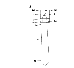
Fig. 1 is the front view of the "necktie-body";
Fig. 2 is the perspective view of the "knot-forming core" made
of synthetic resin or other material;
Figs. 3-A to 3-D are the rear views of the "necktie-body",
showing the process for forming the knot using the core;
Fig. 4 is the front view of the completed "Y-shaped necktie",
which has a necktie-panel, a knot, and a pair of arms for jointing;
Fig. 5 is the sectional view of the "core", showing the
appearance of it when the knot is formed;
Fig. 6 is the sectional view of another type of the "core" which
has a locking-slot in its projection and a cover (projection-cover) with a
locking-pin hinged on its outer end of its projection;
,,
~t~..E
4
Fig. 7 is the sectional view of still another type of the "core"
which has a U-shaped press stud;
Figs. 8-A to 8-E are the rear views of another type of the
necktie-body which has an additional "back-panel", showing the process for
forming the knot;
Figs. 9-A to 9-E are the rear views of still another type of the
necktie-body which has an additional back-panel, showing the process for
forming the knot;
Fig. 10 is the perspective view of the "necktie-band" for the
band-type;
Fig. 11 is the partial front view of the completed necktie for
the band-type;
Fig. 12 is the partial rear view of the "necktie-body" for the
string-type;
Fig. 13 is the sectional view of the "core" for the string-type;
Fig. 14 is the sectional view of the "core" for the string-type,
taken along the section line I-I of the Fig. 13;
Fig. 15 is the sectional view of the "core" for the string-type,
showing the state when the projection is pressed;
Fig. 16 is the sectional view of the "core" for the string-type,
showing the state when the projection is released;
5
Brief description of parts of invention in drawings
1; necktie-panel 1a: combining hole
1 b; narrow part of the panel
1 c; wide part of the panel
1 r; back-panel
1 ra;combining hole of the back-panel
2; knot-cloth 2a; combining hole
3; necktie-arm3a; jointing tool
3b; connecting hole
3c; string-way
4; core-body 4a; string-way
4b; inner cavity
4c; cover (cavity-cover)
5; combining
projection
5a; inner part (having small
diameter)
5b; outer part (having large
diameter)
5c; cover (projection-cover)
5d; locking pin
5e; locking slot
5f; U-shaped press stud
6; band-body 6a; length-adjusting buckle
6b; jointing tool
6c; connecting hook
7; spring
8; slider 8a; string-way
N; necktie-body (basic-type)
N'; necktie-body (band-type)
Nn; necktie-body (string-type)
C; core (basic-type)
C"; core (string-type)
L; shirt-lapel L"; inverted-T-shaped press stud attached on shirt-lapel
S; string
DESCRIPTION OF PREFERRED EMBODIMENTS
As described above, the Y-shaped necktie is formed merely
by assembling the "necktie-body" made of cloth and the "knot-forming core"
made of synthetic resin or other material. After forming the Y-shaped necktie,
the user may put on and take off the necktie simply by using one or other
kinds
of jointing means. Here, three types of preferred embodiments (basic-type,
band-type, and string-type) classified according to the jointing means are
suggested and will be separately described as follows.
1. Forming and Wearing of Basic-Type Necktie (1st Embodiment)
The basic type necktie composed of a necktie-body N and a
core C is produced as follows.
As shown in FIG. 1, the necktie-body N comprises three
components; a necktie-panel 1, a knot-cloth 2, and a pair of necktie-arms 3.
The necktie-panel 1 has a shape as when one has cut off the
traditional necktie at a position spaced about 3 cm above the desired knot-
forming position. The necktie-panel has a combining hole 1 a at its top
(narrower
part) for combining the necktie-body and the core.
The knot-cloth 2 is the rectangular piece of cloth having the
predetermined width and length corresponding to the size of the desired knot.
The knot-cloth has a pair of combining holes 2a,2a in each of its lower
corners.
The knot-cloth 2 is to be sewed to the necktie-panel 1 at the desired
knot-forming position, crossing with the necktie-panel at the right angle.
A pair of necktie-arms 3 is to be sewed to each of the upper
corners of the knot-cloth 2 respectively. On the free end of each of the
necktie-arms 3 is attached one or another of such jointing tools as Velcro
(trademark) - tape, hook, press studs, or magnetic snap-fastener.
As shown in Figs. 2, 5, 6, 7, the knot-forming core C has two
integrants, the "core-body" 4 having the same shape and size as the desired
knot, and the "projected part" on its back for combining the necktie-body and
the
core (hereinafter the projected part is referred to as "combining projection"
or
simply "projection"). Both integrants are made of synthetic resin or other
hard
material integrally in one moulding.
The combining projection is to be made, that the inner part
of it (where it adjoins the core-body) has a small diameter while the outer
part
of it has a larger diameter or a larger diameter disc, in order to prevent the
combining holes 1 a,2a,2a, of the necktie-body N from drifting away from the
projection after they have been combined to the core, thereby achieving a more
stable combination of the necktie-body and the core.
After production of both the necktie-body N and the core C,
the combining process of the two is as shown in FIGS. 3-A to 3-D, namely: (1 )
first the core is placed on the rear side of the necktie-body at the knot-
forming
position with the projection upside (FIG. 3-A), (2) then the two combining
holes
2a,2a of the knot-cloth 2 are to be fitted around the projection of the core 5
(FIGS. 3-B, 3-C), (3) and then the combining hole (1 a) of the necktie-panel 1
is
to be fitted around the projection of the core 5 (FIG. 3-D).
s
Having finished the above process of combining the three
holes around the projection, the necktie-knot is formed of itself, and the
user can
have a "Y-shaped necktie" having a necktie-panel, a triangular knot K, and
a pair of necktie-arms 3 at each of the two top corners of the knot (FIG. 4).
If the combining projection has a locking slot 5e and a cover
5c (hereinafter referred to as "projection-cover") which has a larger diameter
than the projection and which has a counterpart locking-pin 5d to be snapped
into the locking pin 5e as shown in FIG. 6, the user can make the combining of
the necktie-body and the core more tight by snapping the pin 5d and the slot
5e
together after fitting the combining holes 1 a,2a,2a of the necktie-body
around
the projection of the core 5.
Or if the rear end of the projection 5 of the core C is made of
a U-shaped press stud as shown in FIG. 7, the user can put on the Y-shaped
necktie simply by fastening the U-shaped press stud to the counterpart
inverted
T-shaped press stud L' which is attached to the top button-hole place of the
shirt- or blouse- lapel L.
The Y-shaped necktie whose knot K is formed as described
above is very easily put on or taken off, simply by jointing or unjointing of
the
jointing tools attached at each of the necktie-arms such as Velcro (trademark)-
tape, hook, press studs, or magnetic snap-fastener to or from the counterpart
jointing tools attached on the cloth under the collar of the shirt or blouse.
The
user can also tighten or loosen the necktie simply by choosing the jointing
position of the above jointing tools.
For those who prefer to have the traditional style necktie
which has an additional narrower back-panel when the knot is formed, the
Y-shaped necktie can also be furnished with an additional back-panel 1 r. The
narrower back-panel 1 r can be attached to the rear side of the necktie-panel
1
as shown in FIG. 8, or it can be separately prepared as shown in FIG. 9. When
a separate back-panel is used, it must have a combining hole 1 ra at the top
of
it, and the user must combine the hole Ira of the back panel around the
projection of the core before combining the holes 2a,2a,1 a of the knot-cloth
and
the necktie-panel as shown in FIGS. 9-A to 9-E.
2. Forming and Wearing of Band-Type Necktie (2nd Embodiment)
This embodiment is the one which enables the user to put on
the above-mentioned Y-shaped necktie by using a band.
Here, the process of forming the Y-shaped necktie by
assembling the necktie-body N' and the core C is the same as in the basic-
type.
The only difference in the necktie-body N' in this embodiment is that at the
free
edge of one of the two necktie-arms 3 is located a hole 3b for connecting the
band (hereinafter the hole is referred to as a "connecting hole") as shown in
FIG.
11.
As shown in FIG. 10, the band is so made that at the middle
of the band-body 6 is inserted a length-adjusting buckle 6a which has two
rings,
and to which is fixed one end of the band-body 6. On the band-body between
the length-adjusting buckle and the above-mentioned end of the band-body is
inserted a connecting hook 6c which is to be connected detachably of the
connecting hole 3b made at the edge of one of the necktie-arms 3. At the other
end of the band-body is attached such jointing tools 6b as a Velcro
(trademark) -
tape, hook or press studs. The band is so made that the user can adjust the
length of it according to his or her neck size simply by changing the position
of
the length-adjusting buckle 6a on the band-body, and can keep the adjusted
length once the length is adjusted.
..,
10
The process of putting on the necktie with the band is as
shown in FIG. 11. The user must (1) first adjust the length of the band by
manipulating the position of the length-adjusting buckle 6a, (2) and then
connect
the connecting hook 6c of the band to the connecting hole 3b in one of the
necktie-arm 3, (3) and then surround the band around the user's neck under the
collar of the shirt or the blouse, (4) and then joint the jointing tools
attached at
the other end of the band to the counterpart jointing tools attached at the
other necktie-arm. The user can also tighten or loosen the necktie simply by
changing the jointing position of the jointing tools.
3. Forming and Wearing of String-Type Necktie (3rd Embodiment)
This embodiment is the one which enables the user to put on
the above-mentioned Y-shaped necktie by using a string instead of the
above-mentioned jointing tools such as Velcro (trademark) - tapes.
Here, the process of forming the Y-shaped necktie by
assembling the necktie-body N" and the core C" is almost the same as in the
basic-type. The difference in the necktie-body N" of this embodiment is that
each of the two necktie-arms here has a string-way 3c,3c, respectively,
namely,
the hole-shaped tube through which each end of the string is to penetrate from
top to bottom of the respective necktie-arm as shown in FIG. 12.
The knot-forming core C" of this embodiment is much
different from that in the basic-type as shown in FIGS. 13 and 14. The core,
too,
must have two string-ways 4a,4a which run from two places on the top to one
common place at the bottom, in order for the two ends of the string to
penetrate
through and converge at the common bottom of the core. It must also have an
inner cavity 4b in the interior of the core-body where a slider 8 and a spring
7 is
to be installed.
11 c~ ~ ~~ ~
The slider in the inner cavity, too, must have two string-ways
8a,8a which run from top to bottom, in order for the two ends of the string to
penetrate through. Here, the combining projection 5 at the rear side of the
core
is not moulded at the back of the core-body as in the basic-type but is
integrally
moulded at the rear side of the slider, and is separated from the back surface
of the core-body by a slight interval in order for the projection to be
movable
forward and backward together with the slider. A spring or other elastic
material
is to be installed in front of the slider, so that the slider can slide
forward or
backward in the inner cavity by means of the elasticity of the spring
according
as the combining projection is pressed or released.
After the slider and the spring have been properly installed,
the inner cavity must be shielded with a cover 4c (hereinafter, the cover for
inner
cavity is referred to as "cavity-cover").
The core C" of this embodiment described above operates
as follows. When the user presses the projection 5 at the rear of the core C",
the slider 8 moves forward compressing the spring 7) and the two string-ways
8a,8a of the slider become aligned with the respective counterpart string-ways
4a,4a of the core-body 4, thereby enabling the strings in the string-ways to
move
upward or downward. And when the user releases the projection 5 at the rear
of the core C", the slider 8 moves backward by the restoring force of the
spring
7 and the two string-ways 8a,8a of the slider become misaligned with the
respective string-ways 4a,4a of the core-body 4, thereby fixing the strings at
their present position.
In this embodiment also the way to form the Y-shaped necktie
with the necktie-body N" and the core C" is almost the same as in the basic-
type
as shown in FIGS. 3-A to 3-D. The only difference is that, before combining
the
necktie-body and the core, the user must insert each end of string S into the
12 e'
respective string-ways 3c,3c of the necktie-arms from top to bottom, then into
the respective string-ways 4a,4a of the upper part of the core-body 4, and
then
into the respective string-ways 8a,8a of the slider (here the user needs to
press
the projection of the core to align the string-ways), and then into the
respective
string-ways 4a,4a of the lower part of the core-body 4, until both ends of the
string S penetrate out of the bottom of the core-body 4. When both ends of the
string have been taken out of the bottom of the core, the string forms a tie-
loop.
The way to put on and take off the above Y-shaped necktie
is as follows. By pressing the projection 5 of the core C", the user can
loosen
the tie-loop, then the user can hang the string around the collar of the shirt
or
blouse. In this state, the user can tighten or loosen the tie-loop simply by
holding both ends of the string in one hand and pulling up and down of the
core
with the other hand while pressing the projection of the core. In order to
take off
the necktie, the user can loosen the tie-loop and take it off from under the
collar
of the shirt or blouse.
Effects of invention
The main merit of the necktie of the present invention is that
the user can form the knot very easily merely by assembling the necktie-body
made of cloth and the core made of synthetic resin. Another merit is that, as
the
knot-shape is maintainable once it is formed, the user can put on or take off
the
necktie very conveniently simply by applying jointing tools (such as Velcro
(trademark) - tape attached both at the necktie-arms and under the collar of
the
shirt or clothing) or a band or a string. Still another merit is that the user
can
disassemble or reassemble the knot when washing and ironing is needed.
The necktie of the present invention exhibits a nice
appearance without compressing the user's neck, and therefore causes no such
discomforts around the neck as poor blood circulation or ventilation problems.
13
In addition, the necktie of this invention is economical in that it uses about
half
the amount of fabric which is used in making a traditional necktie.
Furthermore,
different from traditional neckties which are sometimes used in such criminal
acts as strangling or tying of the wrists or ankles, the necktie of this
invention is
safe from such criminal actions.