Note: Descriptions are shown in the official language in which they were submitted.
~138S69
,
Translation
B15770PC/Bag. 2116
563-291
SPECIFICATION
DRAW PROCESS
This invention relates to a method of drawing
yarns in a draw zone which is equipped with a tempering
device for influencing the temperature of the yarn, and an
apparatus for drawing a yarn advancing through a draw zone
with a tempering device for influencing the yarn
temperature.
Such a method or such an apparatus are known,
for example, from DE-OS 38 08 854, as well as from DE-PS
33 46 677, and DE-AS 22 04 535. In the known draw
systems, the yarn is drawn by pulling it off the spinneret
at very high withdrawal speeds and/or by the speed
difference of two interposed draw rolls, and in each case
it is heated in the draw zone. This invention is,
however, not limited to such methods, but is suitable for
all draw systems, which are equipped with tempering
devices for influencing the yarn temperature.
In the art, there exists a factor of uncertainty
in keeping the process parameters and the produced yarn
properties constant in time, namely, in that the heat
transfer between the yarn and the tempering device for
influencing the yarn temperature, for example, a heated
draw roll, heated tube, or cooling device (see, for
example German Utility Model 9306510) does not remain
constant, but changes in the course of time. Such
unintended changes in the heat transfer cannot be
detected, since in a continuous operation it is not
possible to accurately measure the yarn temperature from
the viewpoint of the measuring technology, whereas the
;~1386~9
temperature of the device for influencing the yarn
temperature (hereafter described as tempering device) is
controllable, though, but fails to be indicative of the
actual heat exchange. Such variations in the exchange of
heat, may originate, for example, from contaminations or
wear or other operational, but unforeseen changes.
It is the object of this invention to describe a
method and an apparatus, which allow the detect and
eliminate unforeseen variations in the heat exchange
between the tempering device and the yarn or their
consequences.
The solution results from a method as claimed in
claim 1 or an apparatus as claimed in claim 5.
Advantageous embodiments are described in each of the
dependent claims.
In accordance with the invention, the method of
drawing yarns in a draw zone equipped with a tempering
device for influencing the temperature of the yarn is
characterized in that the yarn temperature influencing
effect of the tempering device on the yarn is controlled
as a function of a control signal, which is derived from
the yarn tensile force (yarn tension) that is continuously
measured at a measuring point within or downstream of the
draw zone, the measuring point being selected such that
the yarn speed remains substantially constant between the
heating system and the measuring point. The formation of
a difference between the actual value of the yarn tension
and an predeterminable desired value is a further
development, which has the advantage that from the
viewpoint of process engineering an optimal input of the
yarn tension is initially possible, and that only the
variations from this input are detected and converted for
adjusting the temperature of the tempering device, i.e.,
the heating or the cooling system.
'~13~69
, .
The invention relates likewise to an apparatus
for drawing a yarn advancing through a draw zone, which is
provided with a tempering device for influencing the yarn
temperature, and especially suitable for carrying out the
method of the present invention. This apparatus
comprises, in the draw zone or downstream thereof, a
device for measuring continuously or at intervals the yarn
tension, and an electronic evaluation unit for converting
found variations of the tension into correcting signals,
which is connected via a signal line with the device for
measuring the yarn tension and, furthermore, with a
temperature control of the tempering device.
The tempering device may be a heating device,
with the device for measuring the yarn tension being
connected via the signal line and the electronic
evaluation unit with the device for controlling the
temperature of the heating device. The preparation of
measuring signals and the generation of correcting signals
as a function of the variation of a measured actual value
from a predetermined desired value may naturally be
integrated already in the device for measuring the yarn
tension with the further processing occurring then in the
electronic evaluation unit.
In a draw system having a heated draw roll or
godet and arrangements for influencing or controlling the
godet temperature, the device for measuring the yarn
tension is located, for example, downstream of the draw
roll forming the end of the draw zone. It transmits the
measured actual values or correcting values derived
therefrom, via a signal line and an electronic evaluation
unit for influencing the godet temperature, to a device
for the control thereof.
For purposes of influencing, as a function of
the yarn tension, the signals supplied by a central
control unit for the godet heating, the actual value
2138~9
signals or signals derived therefrom may be supplied, for
example, to one of the correcting value generators which
follow the central control unit. In so doing, it has
shown to be favorable for stabilizing the yarn tension,
when the heated draw roll is preceded by a predraw godet.
Advantageously, also the predraw godet is heated. In
particular, with the use of an -- unheated or heated --
predraw godet, it is possible to arrange the device for
measuring the yarn tension also between the two godets.
The method of the present invention may be
employed in all draw systems, in which the temperature of
the yarn advancing through the draw zone is influenced,
aside from the aforesaid heated godet, by a heating
device, such as, for example, a heating tube of any
design, a hot plate, a heating chamber, or also by a
cooling device.
Thus, in a special further development of the
invention, the device for influencing the yarn temperature
comprises, for example, a cooling tube as a cooling device
with a controllable cooling effect, and with its wall
being provided with air supply openings, which are
associated with at least one adjustable throttle or
shutter for controlling the air quantity and, thus, the
cooling effect. The signals, which are in this embodiment
supplied by the device for measuring the yarn tension
arranged downstream of the cooling device, serve to adjust
the throttle(s) or shutter(s).
The invention is based on the recognition, as
has been verified by extensive tests, that the progression
of the heat transfer influences the yarn tension very
considerably, it being possible to measure the yarn
tension upstream or downstream of the tempering device.
When the yarn tension is measured upstream of the
tempering device, it will be necessary that the measuring
occur in the draw zone, in which also the tempering device
6 6 9
is arranged. When the yarn tension is measured downstream
of the tempering device, the measuring may again occur
directly below the tempering device, but also with a godet
interposed. It has shown that even in subsequent
processing zones, for example, in the takeup zone, the
adjusted level of the yarn tension will undergo a change,
when the heat transfer varies (see, not yet published
German Application P 43 00 633.7). However, it is
necessary that the yarn speed be substantially constant
from the end of the tempering device to the measuring
point of the yarn tension, i.e., there must be a defined
advance of the yarn between the tempering device and the
measuring point, so that the yarn tension cannot be
changed by additional influences.
In this instance, one may proceed in such a
manner that the actual values of the yarn tension measured
at the measuring point are compared with a predeterminable
(possibly time-dependent) desired value, with correcting
signals for controlling the godet temperature being
determined from the variations of the actual values of the
yarn tension from the desired value. Basis for a (time-
dependent or constant) desired value to be predetermined
may be, for example, empirical values, such as are
obtained from an evaluation of recorded production data,
or the mean value of such empirical values. When
processing the registered variations of the tension from
the desired value, it will be advantageous to consider a
tolerance range, which may likewise be established based
on empirical values.
The measuring signals originating from the
variations in the yarn tension and converted into
correcting signals allow to modify, in accordance with the
invention, the temperature of the tempering device, which
is predetermined by a central control unit, so that the
yarn tension does not leave a tolerance range which has
~138669
been predetermined for the chronological progression of
the yarn tension.
Referring now to embodiments of the apparatus of
the present invention as illustrated in the drawing, the
invention is described in more detail.
In the drawing:
Figure 1 is a schematic view of a spin draw
system with a draw zone between two godets and the device
for measuring the yarn tension downstream of the second
godet;
Figure 2 is a schematic view of a spin draw
system as in Figure 1, however, with the device for
measuring the yarn tension being arranged in the draw
zone;
Figure 3 is a schematic view of a spin draw
system without godets and with a tubular heater and the
device for measuring the yarn tension being arranged
downstream of the tubular heater;
Figure 4 shows a draw system with hot a plate;
Figure 5 shows a spin draw system with a
controlled cooling shaft and delivery godet as well as a
device for measuring the yarn tension downstream of the
godet; and
Figure 6 is a schematic view of a spin draw
system as in Figure 2, however with a heated godet
upstream of the draw zone.
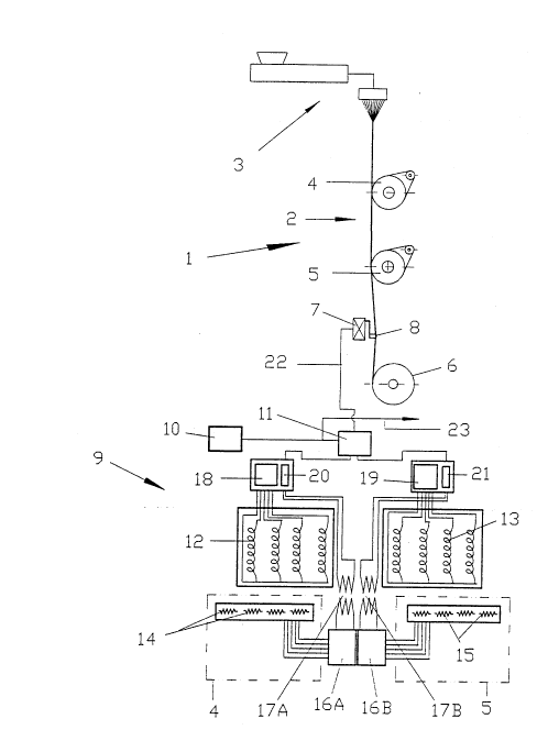
Schematically illustrated in Figure 1 is a draw
system 1 represented only by a spin system 3, a draw zone
2 defined by two godets 4 and 5, and a takeup 6. Arranged
between draw roll or godet 5 and takeup 6 forming the
outlet end of draw zone 2 is a device 7 for measuring the
yarn tension, for example, a yarn tension sensor 8
equipped with an inline yarn tension measuring head as
described in the not yet published German Application P 43
00 633.7. This device 7, 8 for measuring the yarn tension
2138S6~
is connected via a signal line 22 with an electronic
evaluation unit 11, in which the yarn tension fluctuations
measured by device 7 for detecting the yarn tension are
compared with desired values and converted into correcting
values, and supplied to the signals originating from a
central control unit 10.
The lower portion of the drawing is a schematic
view of a godet heating with a temperature control for two
godets 4 and 5. The uniform control signals which are
generated in central control unit 10, for example, for all
processing positions 1 of a machine, of which only one is
shown, advance via a line 23 to the electronic evaluation
unit 11 associated to each draw system, in which these
signals receive the correction signals. The thus modified
signals are input in the temperature control units 20 and
21 associated to the two godets 4 and 5 with heaters 12
and 13.
The temperature values which are generated by
temperature sensors 14, 15 arranged in godets 4, 5 are
converted, for example digitized, into signals in
measuring converters 16A, 17B, and advance via measuring
transformers 17A, 17B likewise to temperature control
units 20, 21, which allow to define -- based on both the
signals originating from the correcting value generator
and the actual value signals -- the amount of the energy
supply to the godet heating system, which is effected by
two HF supplies 18, 19 associated to heaters 12, 13.
In this manner, the basic adjustment serving to
predetermine a constant godet temperature is modified such
that changes in the yarn temperatures leading to
fluctuations in the yarn tension are corrected.
Figures 2 to 6 illustrate further embodiments of
the draw system in accordance with the invention.
Thus, the subject matter of Figure 2 is a draw
system 1, which differs from that shown in Figure 1 in
2133~6~
that the device 7 for detecting the yarn tension is
provided between the two godets 4 and 5, of which the
second one can be heated, and that the yarn tension
fluctuations are measured within draw zone 2.
Figure 3 illustrates an embodiment of a spin
draw system in accordance with the invention without
godets. Between spin system 3 and takeup 6, the yarn
passes through a tubular heater 24. The device 7, 8 for
measuring the yarn tension is provided between tubular
heater 24 and takeup 6. The signals generated by same
from the fluctuations in the yarn tension advance via
signal line 22, and the temperature signals generated by a
temperature sensor 27 arranged in tubular heater 24
advance via a signal line 31 to electronic evaluation unit
11, where the desired values predetermined by central
control unit 10 and, thus, energy supply 29 of the tubular
heater are modified as a function of the actual value
signals originating from the measuring of the yarn tension
and the measuring of the temperature. If, as a further
development, a godet is provided between the end of
tubular heater 24 and takeup 6, it will be possible to
arrange the device 7, 8 for detecting the yarn tension
between tubular heater 24 and the godet (not shown), or
between the latter and takeup 6.
As a tubular heater 24 such may be used which
has a fixed length and controls the heating effect on the
yarn by changing the temperature in the interior of
tubular heater 24. It is also possible to use a tubular
heater 24 with an inside temperature which is kept
constant, and in which the change of the heating effect on
the yarn necessary to correct the yarn tension
fluctuations occurs as a result of changing the length of
the heating tube. Accordingly, it is then possible to use
the correcting signals, which originate from measuring the
yarn tension, which advance via signal line 22 to
213~66~
electronic evaluation unit 11, and which are then further
transmitted to change the length of the tubular heater as
a function of the yarn tension.
A further embodiment of the draw system in
accordance with the invention is shown in Figure 4. The
possibly partially oriented yarn is supplied over a
deflection roll 28, and advances over a first godet 4 into
draw zone 2, where is heated by being guided over a hot
plate 25. It is then withdrawn by draw roll 5 and after
passing through device 7, 8 for measuring the yarn
tension, and after converting the measured tension
variations into correcting signals, it reaches takeup 6.
The signals generated by device 7, 8 advance via signal
lines 22 to electronic evaluation unit 11, where they are
used, together with the correcting signals originating
from temperature monitor 27, for the correction of the
desired value signals originating from central control
unit 10 and, thus, for the energy supply via a
schematically indicated connecting line 29.
Finally, shown in Figure 5 is a schematic view
of a spin draw system equipped in accordance with the
invention, which differs from the foregoing embodiments in
that the device for influencing the yarn temperature is a
cooling device 26 (air flow) with a controllable cooling
effect, which is arranged substantially subjacent spin
system 3 and monitored by a temperature sensor 27. The
device 7, 8 for measuring the yarn tension is arranged
downstream of the cooling device and connected via a
signal line 22 and an electronic evaluation unit 11 with
the device for controlling the cooling effect of cooling
device 26.
In the illustrated embodiment, the cooling
device is a cooling tube 26 with air supply openings
provided in its wall. Associated to the latter is at
least one adjustable throttle or shutter. Accordingly,
2138~63
the signals originating from device 7, 8 for measuring the
yarn tension are transmitted via a signal line 22, to a
device not shown for adjusting possibly several throttles
or shutters via a control line 30, the device being
controlled via electronic evaluation unit 11.
It should further be noted that the bundle of
filaments shown in the drawing of Figure 5, must be cooled
before being combined to a yarn to such an extent that the
filaments do no longer stick to one another, i.e., a yarn
guide causing them to combine is arranged preferably in or
at the outlet end of cooling shaft 26.
Shown in Figure 6 is yet another embodiment of a
draw system 1 similar to that of Figure 2. Here again,
the device 7 for detecting the yarn tension is provided
between the two godets 4 and 5, and the yarn tension
fluctuations are measured within draw zone 2. In this
embodiment the first godet 4 is heated.
The invention has been described with reference
to draw and spin draw systems illustrated in the attached
drawing. It is however not limited to the illustrated and
described embodiments, but can be used with success in all
draw systems equipped with a device for influencing the
yarn temperature for purposes of improving the quality of
drawn products.
~138S69
NOMENCLATURE
1 Draw system
2 Draw zone
3 Feed roll
4 Godet
Godet, draw roll
6 Takeup
7 Yarn tension measuring head (for measuring the
tensile force of the yarn)
8 Yarn tension sensor
9 Heating diagram
Central control unit
11 Electronic evaluation unit
12 Godet heater
13 Godet heater
14 Temperature sensor
Temperature sensor
16 Measuring converter
17 Measuring transformer
18 HF supply
19 HF supply
Temperature control
21 Temperature control
22 Signal line
23 Signal line
24 Heating chamber, tubular heater
Hot plate
26 Cooling shaft
27 Temperature sensor
28 Deflection roll
29 Energy supply
Control line
31 Signal line