Note: Descriptions are shown in the official language in which they were submitted.
2138727
LOCALLY POWERED CONTROL SYSTEM HAVING A REMOTE
SENSING UNIT WITH A TWO WIRE CONNECTION
BACKGROUND OF THE INVENTION
It is becoming ever more usual to use electronic controls in place of
electromechanical controls which have been previously used to provide similar
functions. Perhaps this change is most common in space heating and air conditioning
control, where the standard thermostat using a bimetal temperature sensor to operate a
mercury switch is more and more often replaced by an electronic thermostat. There are
a number of reasons for replacing the electromechanical controls with electronicchcuil~y. The electronics may be more reliable, and certainly will provide more
functions than an electromechanical control. The electronic control is usually much
more accurate than the electromechanical control.
The invention addresses a particular problem that arises most often when
replacing an electromechanical thermostat with an electronic unit in an existingstructure, but may arise in other contexts as well. This problem is that there are
frequently only two wires present in the existing structure for connecting the thermostat
or other control to the controlled device and thus no convenient way to provide power
for the electronic control. Providing power to operate the electronic control circuits at
the remote location thus becomes a non-trivial problem.
In these situations, a variety of systems are now in use. It is possible to run extra
wires from the controlled system. If standard electrical power is close by, the power
may be derived from it. Some thermostats use so-called power stealing systems whose
rechargeable batteries are charged when the internal thermostat switch is open. Other
thermostats use low power circuitry operated by disposable batteries which must be
periodically replaced.
All of these systems have some disadvantages. The power stealing units suffer
failures of the rechargeable batteries and require a charging circuit. The need to replace
disposable batteries is a nuisance. Running extra wires for thermostats is usually easy
and cheap in new construction, but expensive and time-consuming in existing structures.
And if the thermostat or other control device is located at an extremely remote location,
then running more than two wires may still be disadvantageous. For all these reasons, it
has been somewhat of a problem to provide electronic control and sensor circuitry at
these remote locations, and in particular, in the case of sophisticated thermostat control
2138727
in older structures. Ironically enough, it is these older buildings which are the ones
which might most benefit from the energy conserving ability provided by the
sophisticated t~lllp~lalule control provided by state of the art electronic thermostats.
BRIEF DESCRIPTION OF THE INVENTION
We propose a different approach which places the operational control function ina local module and sensor and human interface elements in a remote module. The local
and remote modules are designed to be connected by a single pair of wires only, with
power supplied to the remote module by the local module on these two wires. The
remote module's cilcuil~ y is designed to alter its own impedance. The local module is
designed to detect these impedance changes. Times between changes in the impedance
of the remote module encode the information provided to the remote module by thesensor and human interface elements. The switch which actually controls power to the
controlled apparatus (e.g., the furnace or air conditioner in the case of a thermostat
control) is a part of the local module. The local module is located in the vicinity of the
controlled appa~ s or, for that matter, at any location at which power is available, and
then is connected to control the al~p~lus. The remote module may be located at any
convenient site, and in the case of thermostatic control, within the controlled space.
In one embodiment of this invention, the local and remote modules form a
communication system to be operated using electrical power of a first voltage level
supplied at a local site. The local site has a local decoding module having a pair of
power terminals to which the electrical power is to be applied, and first and second local
signal tçrmin~l~. A remotely located switching module has first and second remote
signal terminals for connection to the local signal terminals by a pair of electrical
conductors. The remote module receives a sensor signal indicating the value of an
external condition, which might be in the case of a thermostat, such things as keyboard
data supplied by the occupant, as well as the signal provided by a temperature sensor.
In one embodiment of this invention, the decoding module comprises a power
supply means receiving the power from the power termin~ , and applying a DC signal
voltage level across the local signal terminals and causing current to flow therethrough.
There is also in the decoding module, a current detector sensing the current flowing
through the local signal terminals and providing a pulse width signal dependent on the
time between current level changes.
2138727
The remote switching module comprises a diode having a first terminal
connected to the first remote signal terminal, and a second terminal; a capacitor
connected between the second diode terrnin~l and the second remote signal terrnin~l; a
control circuit receiving operating power from the remote signal tennin~l~, and
receiving the sensor signal, and providing a switching signal having first and second
levels whose durations are dependent on the sensor signal; and a variable impedance
means. The variable impedance means has a pair of switch tçrmin~l.s connected across
the remote signal t~rrnin~ls and a control tçrrnin:~l receiving the switching signal, and
provides first and second predetermined impedance levels between the switch tçrmin~ls
responsive respectively to the first and second levels of the switching signal.
By altering the impedance of the variable impedance means, the amount of
current drawn by the remote switching module is changed. This current flows through
the fixed impedance means, ch~nging the voltage drop across it. The pulse width
detector senses these changes in voltage and provides a pulse width signal which is
dependent on the time between successive changes in the fixed impedance means
voltage.
Typically, different meanings will be assigned to different times between voltage
changes. The remote switching module can for example, vary this time to indicate the
current temperature sensed by a temperature sensor. Where this system is employed as
a part of a thermostat, there will usually be a keypad at the remote switching module,
and other changes in the voltage across the fixed impedance means can be used toindicate a temperature setting entered by the user or selected by a microcontroller within
the remote switching module according to previous data entry by an occupant of the
space where the remote switching module is mounted.
BRIEF DESCRIPTION OF THE DR~WINGS
Fig. 1 is a schematic of a circuit embodying the invention.
Figs. 2 and 3 show alternate arrangements of a part of the circuit of Fig. 1.
DESCRIPTION OF THE PREFERRED EMBODIMENT
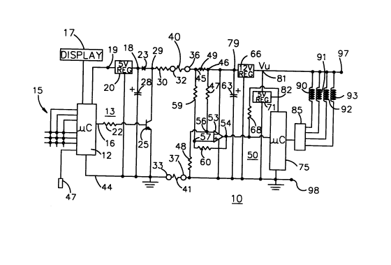
Turning first to Fig. 1, a communication system 10 is shown as comprising a
remote switching module 13 and a local decoding module 50. Power for system 10 is
provided at power tçrrnin~ls 97 and 98 of local module 50, and is shown as an
unregulated DC voltage Vu. Power terminal 98 may be considered to be at a common
213~727
voltage level, negative with respect to Vu in this embodiment. Local decoding module
50 also has local signal termin~l~ 36 and 37. Remote module 13 has a pair of remote
signal termin~l~ 32 and 33 which are connected to local signal terminals 36 and 37
respectively by conductors 40 and 41.
It is convenient to first explain the structure and operation of local module 50.
Throughout this explanation of local module 50, one should assume that module 13 has
the capability of altering the impedance which it presents at local signal terminals 36
and 37. The unregulated DC voltage applied to terminals 97 and 98 is received at a
terminal 81 by a power supply means comprising a voltage regulator 66, and is
converted thereby to regulated 12 v. DC available between power terminal 79 signal
terminal 37 for powering remote module 13 as well as a voltage comparator 53 located
within local module 50. The voltage provided by regulator 66 must be high enough to
provide adequate power to the remote module 13, and for 5 v. circuitry in remotemodule 13, 12 v. is fully adequate. A filter capacitor 63 is connected between power
terminal 79 and common terminal 98 to further smooth the ripples that may be present
in the output of regulator 66. A resistor 49 serves as a fixed impedance to supply
current to signal termin~l 36 from regulator 66. Resistor 49 has a first terminal 45
connected to signal terminal 36 and a second termin~l 46 connected to power supply
terminal 79. The value of resistor 49 should be relatively low, say in the range of 500 to
1000 Q so as to provide adequate but not excessive current flow on path 40 to remote
module 13. There is also a second power supply means comprising a 5 v. voltage
regulator 71 which performs a function similar to that of regulator 66 except that the
unregulated voltage applied at terminal 81 is converted to regulated 5 v. DC at terminal
82. The 5 v. regulator 71 is present to power a microcontroller 75. The voltage
provided by regulator 71 should match the voltage required by microcontroller 75.
One can see that each time remote module 13 alters the impedance presented
across terminals 36 and 37, the level of current flow through resistor 49 will change. A
change in current flow across resistor 49 will of course change the voltage across
resistor 49 as well. The voltage comparator 53 is provided to detect these voltage
changes. Comparator 53 has a - input terminal 56 connected to a first terminal of a
signal resistor 59, whose second terminal is connected to terminal 45 of resistor 49. A +
input terminal 57 of compald~or 53 is connected to receive a fixed reference voltage
2138727
provided by a voltage divider comprising series resistors 47 and 48 connected between
terminal 46 of resistor 49 and signal terminal 37. A voltage feedback resistor 60 is
connected between the output terminal 54 of comparator 53 and its + input terminal 57.
A pull-up resistor 68 connects the 5 v. regulator 71 output at terminal 82 to the output
terminal 54 of comparator 53. Resistors 60 and 68 provide hysteresis in the detection of
voltage changes at input terminals 57 and 57. Comparator 53 may be of the type
available from National Semiconductor Corp. which has the designation LM 393.
Resistor 59 may have an intermediate value on the order of lOK Q, and provides
the signal voltage at termin~l 45 to the + input terminal 57 of comparator 53. The
voltage divider formed by resistors 47 and 48 provides a fixed reference voltage whose
value may be slightly greater than half of the voltage at the output of regulator 66, or in
the range of 6 to 7 v. for the 12 v. output or regulator 66. I prefer that resistors 47 and
48 each have respective values on the order of l OOK Q. At any rate, the voltage drop
across resistor 47 should be somewhat greater than the voltage drop across resistor 49
present when remote module 13 has its high impedance, and somewhat less than thevoltage drop across resistor 49 which occurs when remote module 13 has its low
impedance. As an example, if remote module 13 draws 15 ma. when in its low
impedance mode, and 5 ma. when in its high impedance mode, then the change in
voltage drop across a resistor 49 having a value of 510 Q is from 2.55 v. to 7.65 v., and
the drop across resistor 47 might be chosen to be 5.5 v., which places input terminal 56
at 6.5 v. above the common voltage level of terminal 98. Note that current flow through
resistor 59 is negligible if resistor 60 is very large because the input impedance of
comparator 53 is very large.
Resistor 60 feeds back the output voltage of colllpaldlor 53 so as to provide
hysteresis in the response of compald~or 53 to changes in the signal voltage at minus
terminal 57, resulting in sharp changes in the logic voltage at output terminal 54 of
comparator 53 with little switching noise. Resistor 60 should be many times the value
of resistor 59, say on the order of a megohm or more. Use of a feedback resistor 60 to
provide hysteresis in the output signal of a compald~or is a conventional expedient.
Resistor 68 further controls the hystersis in signal detection at terminal 57 by pulling up
the output voltage from comparator 53 to assure a high logic level at the comparator's
2138727
output t~rmin~l 54, and its use is also conventional. Resistor 68 may have a value
comparable to the value of resistor 59.
Microcontroller 75 is used to perform decoding and control functions at the local
site, based on information provided by the remote module 13 in a manner to be
5 described. Microcontroller 75 may be of the type available from Motorola Inc.,Phoenix, AZ having the designation MC68HC05. The MC68HC05 microcontroller
requires the 5 v. power provided by regulator 82. In the example shown,
microcontroller 75 controls a relay driver unit 85 which in turn actuates relay windings
90-93 which control flow of power to the various elements of an operating system such
10 as a heating or cooling system (not shown). Microcontroller 75 also performs the
function of decoding the signals which the remote module 13 provides. The algorithms
performed by this system for controlling relay driver 85 may be executed exclusively in
microcontroller 75, exclusively in a microcontroller 12 in remote module 13, or by both
of the modules 13 and 50. There is an advantage however, to placing safety-related
functions of a system controlled by relay windings 90-93 in the local module 50 so as to
avoid problems if the data connection between modules should become defective. For
example, if relay winding 90 controls a fuel valve, the algorithms involved with opening
and closing this valve are preferably executed by microcontroller 75.
Turning next to the details of the structure of remote switching module 13, the
impedance changes across its signal terminals 32 and 33 arise from changes in the
impedance of a variable impedance means comprising a resistor 30 and a transistor 25.
Resistor 30 has a first terminal connected to remote signal terminal 32 and a second
terminal 29 connected to the collector of transistor 25. The emitter of transistor 25 is
connected to the common voltage path 44. Transistor 25 may be of the field effect or
bipolar type.
A diode 23 has its anode is connected to the emitter of transistor 25 and its
cathode to the input terminal 18 of a second voltage regulator 20. Regulator 20 thus
receives power from regulator 66 through resistor 49, conductor 40, resistor 30, and
diode 23. A power capacitor 28 is connected between regulator input terminal 18 and
the common voltage path 44. The output terminal 19 of regulator 20 provides 5 v.regulated DC for operating a microcontroller 12. Microcontroller 12 may also be of the
type available from Motorola Inc. having the designation MC68HC05.
213~727
Microcontroller 12 performs the various functions needed for gathering data at
the remote site where module 13 is located and for causing this data to be transmitted to
local module 50. A keypad lS is symbolically shown as providing one set of inputs to
microcontroller 12 through one of its input ports. A temperature sensor 47 is also
5 shown as providing a signal input to microcontroller 12 through another of its input
ports. In certain applications it is convenient to provide a display 17 receiving display
information through an output port for the user so (s)he can determine the current
tenlp~dlule and detect any errors when entering data on keypad 15. Display 17 may
also show status information such as a previous power outage, over-temperature
10 conditions, and the like.
Microcontroller 12 communicates with local module 50 by ch:~nging the
impedance of transistor 25, typically operating it between saturation and cutoff,
although any detectable change in impedance may be suitable. Ch:~nging the impedance
of transistor 25 changes the impedance of module 13 and hence alters the current flow
through resistor 49 in module 50. Where transistor 25 saturates in the low impedance
state for module 13, to allow current flow of 15 ma. through resistor 49 when transistor
25 is saturated, resistor 30 should have a value of 290 Q. An output port 16 of
microcontroller 12 is connected by a current limiting resistor 22 to the base of transistor
25. While a logic signal of a first level is applied to the base of transistor 25 by port 16
of microcontroller 12, the collector to emitter impedance of transistor 25 is relatively
high. While a logic signal of a second level is applied by microcontroller 12 to the base
of transistor 25 through resistor 22, the transistor 25 impedance is relatively low, and
assumed to be negligible in this embodiment. The different impedances of transistor 25
result in different current flow from power supply means 66 through resistor 49. When
the impedance of transistor 25 is high, capacitor 25 charges to the voltage at terminal 29
less one diode voltage drop of around .7 v. In the embodiment of Fig. 1, when the
voltage at the second t~rrnin~l 29 of resistor 30 falls to below that required to provide
the 5 v. output of regulator 20 when the collector-emitter impedance across transistor 25
is low, charge stored on capacitor 28 can supply regulator 20 with current for a period of
time. Diode 23 cuts off in this situation, so that all of the charge on capacitor 28 is
supplied to regulator 20. This provides microcontroller 12 with power while transistor
25 conducts. It is necessary to assure that microcontroller 12 does not ever hold the
2138727
impedance of transistor 25 at a level so low and for a time so long that charge is
depleted in capacitor 28 to an extent that microcontroller 12 cannot function properly.
Discussing next the cooperation between module 13 and a module 50 having the
previously stated component parameters, when transistor 25 has its high impedance,
5 current flow through resistor 49 and connector 40 was assumed to be 5 ma. In this state,
the voltage at both terminals 45 and 57 will be about 9.45 v. because only a negligible
current flows in resistor 59. Because the voltage at input terminal 56 of comparator 53
is about 6.5 v., comparator 53 detects the relatively low voltage drop across resistor 49,
and provides a high logic level signal at output t~rmin~l 54. When transistor 25conducts, approximately 15 ma. flows through resistor 49, and the voltage at terminal 36
has a lower value of perhaps 4.35 v. This level is less than the 6.5 v. at the comparator's
input terminal 56, and the voltage at the output terminal 54 falls to its low level of 0.5 v.
Microcontroller 75 measures the times between level changes in the logic signal at
t~qrrnin~l 54, and can decode the information encoded in it. It is possible to have as
many as several thousand changes in the impedance of remote module 13 each second
and still be easily detectable by local module 50 even in relatively noisy conditions.
Such an information capacity is more than enough for most types of control and
communication required for the application intended.
The duration of relative high and low impedance values can be easily controlled
by microcontroller 12 and easily detected by the microcontroller 50.
Figs. 2 and 3 show alternative designs for the impedance switching in the remotemodule 13. These alternatives reflect the fact that it is only necessary for the variable
impedance means to provide a voltage at terminal 18 adequate to permit the operation of
microcontroller 12 at all times, and to limit current flow through the various components
to a level below their rated values. In Fig. 2, resistor 31 and transistor 25 comprise the
variable impedance means. Resistor 31 provides a fixed impedance to limit current
flowing through transistor 25, and resistor 30 has been omitted. It is also possible to
omit diode 23 if resistor 31 is sufficiently large to assure that the voltage drop across
terminals 32 and 33 is always greater than that required by regulator 20 to provide the
voltage necessary for operating microcontroller 12. Theoretically, capacitor 28 is also
unnecessary so long as the voltage across terminals 32 and 33 is greater than required
for operating microcontroller 12. However, capacitor 28 provides a measure of
2138727
,
protection against voltage surges on conductors 40 and 41, protecting transistor 25
against damage caused thereby.
In the circuit of Fig. 3, no input diode is shown, and resistors 30 and 31 and
transistor 25 comprise the variable impedance means. In this arrangement, the voltage
5 drop across resistor 31 and transistor 25 when in its low impedance state must permit a
voltage at termin~l 29 sufficient to operate microcontroller 12.
The length of conductors 40 and 41 are limited by a number of considerations.
The resistance in them should be small enough to assure that voltage swings at input
terminal 57 are across the fixed voltage at input terminal 56. It is possible to10 compensate for dirrerellL conductor 40 and 41 resistances by ch~nging the resistance of
resistor 30 or 31. Those having skill in circuit design and communication theory will be
easily able to select values for these components as well as the others shown in Figs. 1-3
to implement this communication system.