Note: Descriptions are shown in the official language in which they were submitted.
W094/00928 2 13 8 9 6 1 PCT/GB93/0l353
OPTICAT, SOURC~ FOR COM~UNICATIONS SYST~M
The present invention relates to an optical source for
a communications system and finds particular application in
supplying high frequency signals to a photodetector.
It is known to use a semiconductor laser structure as
a signal source in optical communications. Such structures
usually comprise an active layer of semiconductor material
into which electrical carriers are injected by applying a
drive current. The active layer is provided with optical
confinement and feedback. The injected carriers produce
photons in the active layer which oscillate and multiply by
laser action to produce an optical output, often from an end
facet of the laser structure.
It is known that, in distributed feedback (DFB)
lasers, it is possible to superimpose modulation on the
optical output of a laser by varying the drive current.
Because of physical limitations of the devices, this has only
been done at rates up to about 20GHz. It is also known that
as the drive current power increases, optical sidebands are
seen, separated by the optical modulation frequency. As the
optical frequency deviation of the source increases, more
sidebands are produced, reflecting an overall spectral
spreading of the modulated source.
On a photodetector a received electrical signal is
produced which is given by the (phasor) sum of the beat
signals generated between all pairs of optical sidebands.
The received electrical signal therefore contains components
at multiple harmonics of the modulating frequency. However,
a frequency modulated (FM) or phase modulated (PM) optical
signal results in an electrical signal containing only a D.C.
(zero frequency) component: the summation of beat signals
between sldebands exactl,y cancels .o give zero for the
electrlcai signal components at the modulation frequency and
higher harmonics thereor. Hence, although high frequency
beat signals are present, they do not manifest themselves at
2 conventlonal photode~ector based receiver. In the paper
CA 02138961 1999-01-04
entitled "35GHz Microwave Signal Generation with an
Injection-locked Laser Diode", published in Electronics
Letters 29 August 1985 vol 21 no. 18, L Goldberg et al
describes a system for generating 35GHz signals by
injection locking a slave laser to sidebands of a modulated
master laser output. Using a slave laser which has free-
running modes separated by a frequency difference which
equals a selected beat frequency between sidebands of the
master laser, an output is generated from the slave laser
which comprises two relatively high amplitude signals
separated by that same beat frequency. At a receiver, the
beat frequency appears. However, two laser devices are
required and it can be difficult to achieve a workable
arrangement, it being necessary to provide close wavelength
control. It is also difficult to achieve requisite modes
in the slave laser, spacing of modes being limited by the
length of the device.
An object of the present invention is to provide a
practical optical source for communications systems which
can be used to generate high modulation rate signals which
can be detected by a photodetector.
Embodiments of the present invention can be used to
generate photo-detectable signals at microwave frequencies,
for instance up to of the order of 60GHz or greater.
25Further, it has been found that these detectable
signals can be modulated to carry information, such as
video, signals and, using a photoelectric detector for
instance, the output from a receiver receiving such signals
can be fed directly to a microwave antenna, such as a horn,
providing an optically driven microwave link.
CA 02138961 1999-01-04
Embodiments of the present invention also have the
advantage that they can be fabricated to form only a small
dimensioned package which is particularly convenient in
certain environments.
According to the present invention, there is provided
an optical communications system, comprising:-
an optical signal source, said source having anoptical output,
modulation means to produce modulation in said optical
output, the arrangement being such as to cause optical
sidebands to appear in the optical output,
and modifying means to modify a characteristic of the
optical output so as to allow photodetection of at least
one beat frequency between said sidebands at a receiver
receiving said optical output.
In particular, said characteristic might be a phase or
amplitude characteristic of the optical output. That is,
it has been recognised that including modifying means which
modifies the phase (or amplitude) of the FM or AM sidebands
of the optical source effectively "uncancels" the beating
between optical sidebands, thereby producing a received
electrical signal with components at harmonics of the
original modulating frequency.
As mentioned above, it has also been discovered that
such harmonics can be modulated to carry information
signals such as video signals, and the output from a
detector, or at least from a receiver incorporating a
detector, can be used to feed a microwave antenna directly,
so that an optical fibre fed, information signal carrying
microwave link is produced.
CA 02138961 1999-01-04
A convenient means for modifying phase characteristics
of one or more of the sidebands comprises dispersive
optical fibre. The different sidebands will be phase
shifted so that the beat frequencies between them, the
"harmonics" of the modulation frequency, can be picked up
by the photodetector. For instance, if the laser source is
driven with a 4GHz FM signal and the output passed through
12.5km of conventional step index fibre, phase shifted
optical sidebands received at a detector will beat to
produce a photo current comprising a frequency comb with
4GHz spacing. In the detector, the frequency comb will
produce harmonics significantly above 4GHz, for instance at
40GHz, as a result of beating between optical sidebands
spaced by 10 x 4GHz.
In a possible application, the output of the detector
can then be fed to a microwave antenna and propagated as a
radio frequency (RF) signal in free space thereby. The
beat frequency (eg. 40GHz) signal is then conventionally
detected
W094/00928 PCT/GB93/01353
2~3896l
at a receiving microwave antenna, mixed to a local oscillator
to downconvert to an intermediate frequency, amplified and
fed to an intermediate frequency (IF) receiver.
Notably, in embodiments of the present invention where
dispersive phase shifting is used to achieve harmonic
detection at the photodetector, all the sidebands are
contributing to the RF signal. This is in contrast to the
1985 disclosure of Goldberg et al, referenced above.
Embodiments of the present invention will now be
described, by way of example only, with reference to the
accompanying figures, in which:
Figure 1 shows a schematic diagram of a first
arrangement of an optically fed microwave link carrying a
video signal and comprising an optical signal source
according to an embodiment of the present invention;
Figure 2 shows a graph of modulation depth at the
output of an optical detector, detecting the output of the
optical source of Figure 1 after optical phase shifting by
transmission on a dispersive optical fibre;
Figure 3 shows ~n graphic form a definition of a
Bessel function Jp for a variable x;
Figure ~ shows in more detail the steps in providing
a modulated drive current to a laser slructure in an optical
signal source as shown in Figure l;
Figure 5 shows a schematic diagram of a second
arrangement of an optically fed microwave link carrying a
video signal and comprising an optical signal source
according to an embodiment of the present invention.
Figure 6a) shows a graph of a theoretical relationship
between modulation depth and FM modulation index for a range
of beal frecuencies, or harmonics 10 through 15 of a
moduia~on slgnal; and
Figure 6b) shows a graph cf measured dependence of
moduialion dep=h on arlve current =o a laser structure for
the harmonlcs of Figure 6.
Optical fibre and millimetre-wave radio are both
capable Ol supporting large bandwidth requirements, for
W094/00928 2 1 3589 61 PCT/GB93/01353
instance as associated with broad band services. Running
optical fibre direct to a home or business can provide high
capacity but is not always an appropriate solution for
operational reasons. It is likely that a hybrid network
comprising both radio and fibre will play a significant role
in early broadband local access systems.
Radio transmission in the 60GHz millimetre-wave region
is of special interest because an oxygen absorption peak aids
frequency re-use in a cellular communications environment.
10 In addition, high gain antennae are physically small at this
frequency and could be manufactured cheaply in volume for
consumer applications. However, practical issues such as
cost, size, weight, frequency stability and power consumption
of radio outstations need to be addressed before hardware
could be deployed to provide broadband services at
millimetre-wave frequencies.
In both arrangements of the present invention
described herein direct modulation is applied to a single
mode semiconductor laser to create an optical FM signal.
Dispersion in an optical fibre then perturbs the phase
relationships between the FM side bands in such a way that
the output from the photodetector provides significant power
levels at high order harmonics of the modulation frequency.
With a modulation frequency of 4GHz, considerable power is
obtained beyond the 15th harmonic, that is at frequencies in
excess of 60GHz. Unwanted harmonics could be removed easily
if necessary by electrical filtering after photodetection.
It should also be noted that, because the optical FM
side bands are derived from the same optical mode, the
optical phase noise is cancelled at the photodetector.
Therefore the phase noise is principally determined by that
of the modulzting source. The comDination of efficient
harmon~c ~enera~ion, high spectrz1 purity, compact size, and
the abili_y .o -hoose any frequency (at ieast to 60GHz) makes
this a most a~trac~ive technique for the transmission of
millimelre-wave radio slgnals over optical fibre.
W094/00928 PCT/GB93/01353
-- 6
21 Referring to Figure l, the first arrangement of an
optical fed microwave link of the present invention comprises
a laser source l, supplied with a drive current by a
frequency modulated current source 2, the laser output being
fed via a dispersive 'ibre link 3 to an optical detector 4.
A video signal is superimposed on the FM output of the
current source 2 by a video pattern generator ll. The
electrical output of the detector 4 is fed to a microwave
transmitter 5 which generates a free space signal link 6 to
a microwave receiver 7 whose electrical output is down
converted, amplified and fed to a video receiver 8 according
to known techniques.
The laser source l comprises a single mode DFB laser,
being a bulk device with grating feedback. The optical
15 detector 4 comprises a high gain, high speed detector as
disclosed in International Patent Application number
GB9l/00702 W0, filed on 1st May l99l, priority date 1st May
l990, in the present Applicant's name. The fibre link 3
comprises 12.Skm of conventional step-index single-mode
fibre.
If the laser source l is driven by a signal at 4GHz,
the signal received at the optical detector 4 from the
dispersive fibre link 3 will contain optical sidebands, phase
shifted to produce a photo current output from the detector
4 comprising a frequency comb with 4GHz spacing. In the
detector, the freauency comb will include a beat frequency at
40GHz from signals at lO x 4GHz separation. That 40GHz beat
frequency can be filtered and fed directly to the microwave
transmitter 5. At the receiver 7, the 40GHz signal can be
mixed and downconverted to an intermediate frequency using
conventional techniaues. The downconverted component may
then be passed throu~n an amplifier 15, split and fed to the
video -eceiver ~ e o~ner ~art of the signal output from
the splitter ~ belr.c used _o supply a spectrum analyser lO
for monitoring purposes.
Tn the system aescr~bed above, effectively the tenth
harmonlc of the 4GHz modulatina signal has been selected.
21~8961
W094/00928PCT/GB93/01353
-- 7
CONSTRAINTS AND OPERATING CHARACTERISTICS
There are a number of constraints and characteristics
of the system described above and these are as follows.
Freauencv Devlation
5Referring still to Figure 1, the video receiver 8
requires a FM input of approximately 13MHz deviation. Using
a synthesiser as the current source 2 to produce a 4GHz
frequency modulated drive current to the laser source 1, the
video pattern generator 11 is used to modulate that 4GHz
"carrler". To achieve the 13MHz deviation at the video
receiver input, the frequency deviation at the output of the
current source 2 should be approximately 1.3MHz in view of
the use of the tenth harmonic. The video pattern generator
11, having a nominal output of lv, is used to drive the FM
input of the current source 2, or synthesiser, via a 75/50
Ohm matching pad 14.
4GHz FM to 40GHz AM Conversion EfficiencY
Referring to Figure 2, in selecting the tenth
harmonic, there is a conversion at the optical detector 4 not
only in frequency but also in signal type. That is, the 4GHz
optical FM signal transmitted by the laser source 1 becomes
a 40GHz electrical signal at the output of the optical
detector 4.
In Figure 2, the modulation depth "M" at the output of
the optical detector 4 can be defined as the ratio of the
amplitude of the harmonic Iac to the direct current photo
current IdC. This is seen in Figure 2 as the peak height of
the modulation Iac with respect to the base level 12 provided
by the dc photo current T ~C,
The modulation aepth can however be arrived at by a
separa.e analysls, _s f_llows.
The modulat}~n aep~h, M~, of the pth harmonic is given
by
Mp = 2 Jp (2~ sln (p~)) 1
35 where
W094/00928 - 8 - PCT/GB93/013S3
2~3896~
~ JP is the pth bessel function
is the FM index of the laser and
= Fdeviation/Fmodulation
~ is an angle characterising the dispersion in the
fibre.
The dispersion angle, ~, is given by
~ = (2 ~ Fmod)2 x (-DzA 4~c 2
where
Fmod = laser modulation frequency
= 4GHz in the example
D = fibre dispersion in ps/km/nm
Z = fibre length
A = free space wavelength of light
c = speed of light.
According to equation 1, the maximum modulation depth
of the pth harmonic equals twice the maximum value of the pth
bessel function.
Referring to Figure 3, values of the bessel function
JP for a variable x can be defined as shown. Using this
nomenclature, then the qreatest modulation depth for the pth
harmonic is given by
Mp (max) = 2 JD (j' P, 1 )
and occurs when
2~ sin (p~ p, 1
The values of p, (j'p,1), & Jp(j'p, 1) are tabulated as
follows:
O Cl 1
1 1.84118 .58187
2 .. OS424 .4865
3 - ~.20119 .43439
4 5.~1755 .39965
S ~.1562 .37409
6 ?.5C127 .35414
2138961
W094/00928 PCT/GB93/01353
9 _ ~
7 8.57784 .33793
8 9.64742 .32438
9 10.71228 .3128022
11.7717 .3027425
~ 5 11 12.82729 .2938809
12 13.87962 .285987
13 14.92913 .2788889
14 15.97618 .2724552
17.02105 .2665838
lb 18.06397 .2611935
17 19.10516 .2562191
18 20.14477 .2516072
19 21.18294 .2473137
22.21981 .243302
Theoretically, using the tenth harmonic, the maximum
modulation depth that could be achieved was 60%. However, in
practice, significantly lower modulation depth might be
achieved, for instance of the order of 13%.
It might be noted that ~ gives an approximate
threshold value for appearance of the "nth" harmonic at
approximately equal to n/2.
Fibre Len~th and Dis~ersion
The dispersion, ~, produced by the fibre link 3, has
been set out above at equation 2. Putting in the following
experimental values, a 'ength of 12.5km for the dispersive
fibre link 3 was founa ,o be adequate to give significant
phase shifting between sidebands.
F d = 4GHz
D = 17 ps/km/nm (dispersion)
z = 12.5km (length of fibre)
A = 1550 nm (optical signal wavelength)
This gives a value for DzA of 329nS. 1/c is 5.17 x 10
~ nS. Therefore, ~, ~y SUDS .' tu~ion in equation 2, = 2 ~ x
2.72 :; 10~2.
p~ = 10~ = 2,. :; ~.~72
= Q.27
W094/00928 PCT/GB93/01353
2~3896~ - 10-
For the tenth harmonic, it is desired that p~ = 0.5~.
However, from the above, we have p~ = 0.27~
This gives sin (p~) = sin (0.27~ ) = 0.75
The value of p~ = 0.5~ is optimum in the sense that
5 this value minimises the modulating power that has to be
applied to the laser in order to maximise the 40GHz
component. In the present experiment, z at 12.5km
represented about half the optimum length of fibre, but this
can be compensated by an increase in the modulation index, ~.
FM Deviation of Laser
Going back to equation 1, Mp is maximum when
2~ sin (p~) = j'p,1
= 11.77 for p=10
This gives an estimated value of ~ at approximately
7.8.
The laser drive power at 13.8dBm, 24mW gives a zero to
peak current amplitude of 3lmA.
The FM deviation of the laser is given by
Fdev = ~ x 4GHz = 31.4GHz, so the laser FM efficiency is
given by
~F = lGHz/mA
~' i
RF Pro~aqation
Using a separation of 0.5m between the microwave
25 transmitter 5 and the receiver 7, the measured loss across
the free space signal link 6 was l9.OdB. Theoretically, with
a path loss across the link 6 of 60dB, and antenna gains at
the microwave transmitter and receiver 5, 7 of 21.5dB each,
one would expect the net loss to be 17.OdB. (It should be
noted however that 0.5m is not a distance clearly related to
either the near or the far fields in these circumstances and
the es.imate at 17.OBb for the net loss can only be treated
as approximate.j
Down Converslon
W094/00928 2 1 3 8 9 61 PCT/GB93/01353
Loss at the downconverter 13, the measured power 108s
from the 40GHz signal from the microwave receiver 7 to the
intermediate frequency signal output by the down- converter
13, was measured as 11.7dB, using a 9.6dBm 39GHz input at the
LO part of the down-converter 13.
Video FM Transfer
Referring to Figure 4, there is a voltage reduction
V2/Vl due to the 75/50 Ohm matching pad 14 of 0.424, for a
video output of V1 at lV. Using a synthesiser 2 set to give
4.65MHz/RMS (Root Mean Square) Volt, the FM deviation "~f"
per Volt at V2 is given by
~ f/V2 = (1/~2) x 4.65
giving ~f/VI = (1/~2) x 4.65 x 0.424
= 1.52MHz/V.
The FM transfer coefficient was measured directly for the
4GHz and 40GHz components:
~Vpkpk f pk-pk ~f/~V
4GHz 1.0V 1.38MHz 1.38MHz/V
40GHz 150mV 2.04MHz 13.3MHz/V
This gave a measured FM transfer coefficient at 40GHz
of 13.3MHz/V compared with a calculated value of 15.2MHz/V.
Other Factors
Looking at the threshold sensitivity of the video
receiver 8, the calculated threshold sensitivity was found to
be -86dBm. The experimental threshold was found to be
-85dBm. No significant extra noise is introduced by the
optical link but it is thought that the line amplifier 15 may
have a small effect.
Concerning qain at the line amplifier 15 and the
8~ splitter ~, the ~ombined gain was found to be 4dB.
Power budqet
Factors in the power budget at the microwave
~ransmitter 5 are as r ol l ows:
W094/00928 PCT/GB93/013~3
2138~ 61 - 12 -
Reference (OdBm optical power) = -14.1
Optical input power (twice -ldBm) = -2.0
Responsivity = +5.2
Ideal modulation depth = -10.5
FM/AM inefficiency = -7.0
Detector roll off = -12.5
50 Ohm matching = 0.0
Electric power = -40.9dBm
Including the rest of the system, the power budget is
then as follows:
= -40.9dBm
Path loss (0.5m) = -60.OdB
Transmitter horn gain = +21.5
Receiver horn gain = +21.5
Received power = -57.9dBm
Excess path loss = 1.9dBm
Net received power = -59.8dBm
Conversion loss = -11.7dB
Line amplifier/splitter = +4.OdB
Video received power = -67.5dm
Threshold power = -85.OdBm
Margin = 17.5dB
It should be noted that, although a microwave horn is
described at the microwave transmitter 5 and the microwave
receiver 7, a horn is only one possible type of antenna which
might be used in such ~ transmitter or receiver.
Possible improvements in the system described above
micht be to increase the mlcrowave transmission range. In
~0 order .o transmlt lOC~. an ex~ra 46dB power approxlmately
would be requlrea such =hat the radio ~requency transmitter
gave out perhaps +6dBm. In order to increase transmitter
power, one miaht adjust the followina:
Detectc- roll ~ff
2138961
W094/00928 - 13 - PCT/GB93/01353
optical input powers
impedance matchins
Feasibly, one could achieve -lOdBm transmitted power,
- for instance.
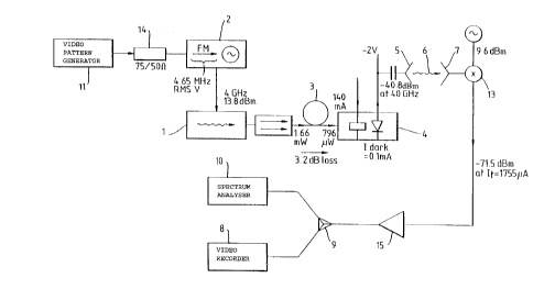
Figure 5 shows a second experimental layout for an
embodiment of the present invention.
A three contact DFB laser 1 is driven by a microwave
oscillator 2 to create an optical FM signal. The microwave
oscillator 2 is itself frequency modulated by an input video
signal 11. The resulting modulated lightwave is transmitted
along 12.5km of standard single mode fibre 3 and detected by
a high speed photodetector 4 which in turn drives the radio
transmitter antenna 5. At the radio receiver, the incoming
signal is down converted to an intermediate frequency (IF)
15 within the band of a satellite TV receiver 8 and then
displayed on a video monitor or a spectrum analyzer 10.
The three contact DFB laser 1 comprises a device 350~m
long, the outer contacts of which are connected together.
The outer contacts are biased at 90mA while the centre
contact is biased at 30mA. Under these conditions, the
output power (after optical isolation) was 1.6mW at a
wavelength of 1556nm, and the FM efficiency (driving the
centre contact) was l.OGHz/mA at the microwave oscillator
frequency OI 4GHz. The oscillator power was set to a level
of +14 dBm, which was found to maximise the magnitude of the
tenth harmonic at 40GHz (the highest frequency for which the
radio receiver equipment was readily available).
The pigtailed high speed photodetector 4 was a
monolithically integrated optical pre-amplifier and edge-
coupled PIN photodiode, with a responsivity of 0.61A/W at40GHz. A bias tee and a waveguide-to-coaxial transition were
used to connect the photodiode directly to a standard gain
(21.5 dB) horn antenna to form the radio transmitter. The
- optlcal ~ower 1evel after tne 12.5km of optical fibre was -
1.0 dBm, which produced an electrical power of -40.8 dBm (at
40GHzj at the photodiode output. The 40GHz optical
modulatlon depth at Ihe ?hotodiode was calculated from these
W094/00928 PCT/GB93/01353
- 14 -
2138961
values to be 12%. The 3 dB line width of the 40GHz carrier
(with the video input signal removed) was less than lOHz.
After transmission over 1~ of free space, the power at
the output of the receiver horn 7 was -64.8 dBm. A local
oscillator at 39GHz was used to down convert to an IF of
lGHz. The conversion loss was 11.7 dB and the IF power after
the line amplifier and splitter 9 was -72.5 dBm.
The 4GHz drive frequency to the laser 1 deviates in
response to the video input signal connected to the FM input
of the microwave source 2. The deviation is reflected in the
frequency spacing of the optical FM side bands and the
electrical comb at the output of the photodiode in the
photodetector 4. Each frequency of the comb deviates in
proportion to its harmonic number and the tenth harmonic at
40GHz therefore deviates by ten times the deviation of the
4GHz output of the microwave source 2. The peak FM deviation
required by the video satellite receiver unit is
approximately 14MHz so the FM coefficient of the microwave
source 2 was set to 1.4MHz/V for the video input signal level
of lVpk.
The threshold power level of the video receiver was
-85.0 dBm, giving a margin of 12.5 dB. The calculated FM
threshold power level was -86 dBm, based on a bandwidth of
30MHz, a signal-to-noise ratio of 8 dB, and a receiver noise
figure of 5 dB. Close agreement between the experimental and
calculated threshold power levels indicates that the noise
contributed by the op~ical link can be ignored in this
experimental arrangement.
In practice, a longer radio transmission distance may
30 be necessary. There are a number of improvements which could
be made in the arrangement described above. A possibility
involves a modifiea source which would increase the
modul2.;0n aep~h at the pho~odiode in the pAo~odetector 4.
It has been sAown that ~he maxlmum modulation depth
obtainable for a source witA pure frequency modulation is 60%
for the tenth harmonlc, ana that tAe discrepancy with the
exper~mental vaiue of 12% lS caused by the presence of
2138961
W094/~928 PCT/GB93/01353
- 15 -
significant intensity modulation at the output of the laser
1.
Another possibility is improving the responsivity of
the photodetector 4. Previous examples of this type of
5 photodetector in a different package (without a fibre
pigtail) have shown responsivity values of over 3OA/W at
40GHz. Although saturation of the integrated optical
amplifier and the current handling capability of the
photodiode will set a limit to available output power, a
maximum photocurrent of more than lOmA is not unreasonable.
If this is combined with a modulation depth of 100%, a
millimetre wave power level of more than +4 dBm would be
available, which is greater than a 45 db increase over the
experimental arrangement described above. Narrow band design
and impedance matching at the output of the photodiode may
result in further improvement.
Electrical amplification at the photodetector output
is an obvious way to increase the radio range, but it may be
preferred in practice that an outstationed radio transmitter
be kept relatively simple. Improvements in this area might
arise from a reduction in the number of components and also
a reduction or elimination of their requirements for dc
power.
For point to point applications, the use of
directional antennae rather than standard gain horns could
increase the received millimetre-wave power considerably,
again ieading to increased radio range. The 45 dB increase
in power at the radio transmitter, coupled with 20-30 dB
afforded by the use of directional antennae would lead to a
total increase in received power of 65-75 dB, and therefore
transmission distances greater than lkm would be possible.
mhe experimentai ar_anaement described above uses the
ten~h harmonlc ât 40GHz. In princ1ple, i t would be possible
to move to 60GHz either by increasing the modulation
frequency or by making use of 15th harmonic. Also the system
described above oniy lncorporates a single video channel. It
W094/00928 PCT/GB93/01353
- 16 -
213~961
- may be that embodiments of the present invention would be
suitable in multichannel transmission.
To sum up, the arrangement described above
demonstrates a simple technique for realizing millimetre-wave
radio-fibre systems which does ~not require either a
millimetre-wave source at the optical transmitter 1, or up
conversion at the radio transmitter 5. The technique is
suitable for transmission of FM signals such as wide band
video FM, or continuous wave (CW) signals for remote
10 injection locking applications. The spectral purity of the
CW millimetre-wave signal transmitted in this way is
determined primarily by that of the microwave oscillator.
For practical applications it would be necessary to increa~e
the radio propagation range, but improvements in this area
could make lkm a realistic target.
Publications comprising subject matter relevant to the
above are as follows:
I C Smith and B J Ellis: "A wide band mm-wave Fibre-
fed Radio Distribution Point Demonstrator", ICC92 Conference
Record pages 100-104, June 1992.
G Sherlock, H J Wickes, C A Hunter and N G Walker:
"High Speed, High Efficiency, Tunable DFB Lasers for High
Density WDM Applications~, ECOCg2, Paper Tu P1.1, September
1992.
D Wake: "A 1550nm millimetre-wave Photodetector with
a bandwidth-Efficienc~ Product of 2.4THz~, J Lightwave
Technol., vol. 10 pages 908-912, July 1992.
Although the use of the technique ~for tranmission of
FM video information has been described, it should be noted
30 that other methods of impressing information onto the
transmitted beat signal are possible. For example, the
output of the modulated laser, comprising the optical
siaebanas, car. tself be transmitted throu~h an opticai
in~enslt~ moaulato~ to superlmpose the information to be
3~ communicated. At the receiver, the electrical signal would
then contain beat f-eauencies between the optical sidebands,
each with the information impressed. Such an arrangement
2138g61
W094/00928 - 17 - PCT/GB93/01353
might be used, for example, to transmit multiple video
channels.
It is important to note that, although the arrangement
described above relies on the properties of semiconductor
lasers in generating optical FM, other forms of modulation
- might be substituted, such as phase modulation.
Further, although dispersive fibre 3 is described,
other means for modifying the relative characteristics of the
sidebands might be used, such as a grating pair.
Although the embodiments described above comprise a
laser source 1, this is not essential, it being within the
ambit of the present invention that an optical source be
remote and of any of a number of types, it being sufficient
for the invention that sidebands of the modulation can be
produced, and hence at least one beat frequency.
In a different embodiment of the present invention,
the fifteenth harmonic of a 4GHz signal may for instance be
detected, giving a beat frequency of 60GHz. An arrangement
in which this is the case is described below, together with
some further discussion of aspects of the lnvention.
As described above,
a frequency or ?hase modulated optical signal becomes
ntensity modulated .hrough dispersion in single-mode optical
fibres. Theoretical results describing this effect are
presented below, and supported by observation of 12%
intensity modulation at the 60GHz harmonic of a 4GHz signal
applied to a three-contact DFB laser.
Chromatlc dispersion s known to cause a phase or
frequency moduiated op~ical signai to become intensity
modulated as it propagates along a single-mode optical fibre
[1~. This effect has Deen identified as causing a power
- ?enalty in digital transmisslon systems, and intermodulation
~-ocuc~s ana no1se ln analogue systems f2, 3]. The same
~ecranlsm also causes sianal ~ad ng ln AM systems ~4].
3c Wit... reference tO _hls followlng embodiment, we
L_rther discuss how als?erslon can De used to advantage to
genera~e high _re~uenc-~- mm-wave signals from a source which
W094/00928 PCT/GB93/013~3
2 138g 6 1 - 18 -
is frequency or phase modulated at microwave rates. The
principle is demonstrated by applying a 4GHz drive current to
a split contact DFB laser designed for frequency modulation
and observing the 60GHz, 15th harmonic component of the
intensity variations at the output of 12.Skm of dispersive
single mode fibre.
Theory
Before considering specifically the case of frequency
or phase modulation, we first derive a formula for the
harmonic content of the intensity variations of any
periodically modulated signal mode optical singal propagated
over dispersive fibre. The electric field at the transmitter
can be written in the form
et(t) = f(~t)exp(jvOt) (lb)
~
n--~ Fn exp(j(vO+n~)t) (lb)
where vO is the optical angular frequency of the single mode
source, ~ is the modulating angular frequency and f(~) is a
periodic function with harmonic components Fn given by
f~ = 1 Jf(~)exp(-~n~)dfl
2~ (2)
The fibre transfer characteristic can be written in the form
H(v) = exp(-jk(v)z)
= exp(-j(kG+k~(v-vG)+~k~(v-vc)'+...)z) (3)
where z is the fibre length. In the expansion of the
propagation constant k(n), the first two terms represent a
~ixea ?nase shift and pro?aqat~on delay. We retaln only the
t~-rd =erm (putt-ng ~=k =G), and wrl e
Hn = H(vA+n~) = exp(-jn-~) (4)
CA 02l3896l l999-0l-04
19
where ~ 2k2z parameterises the fibre dispersion at the
operating wavelength and modulation frequ~ncy. The fibre
group delay, ~g for light at frequency v is given by
~ = Zd = zk2(V-vO) ( 5 )
and allows ~ to be related to the group velocity dispersion
parameter, D = (d ~g/dA)/z (normally quoted in ps/(km nm)),
as follows [2]
~=r~2~z_ r~ o~ (6)
The instantaneous optical intensity received after
propagation through the fibre is given by
i(t) ~ I a,(t)l
12
n3~Y~ ~ ~ ( V3 D.
2 0 r~
e~?(i~ ) (7)
where the Ip are the harmonic components of the intensity
variations, and can be evaluated by inserting (4) in (7) .
Expanding the square as a double sum and collecting terms
glves
~.
I~ - Yxp(~?~~ F~ex~(-2jqp~) (8a)
~ ~ J ~ p~).(a-p~)exp(-jp~ (8b)
where to obtain (8b), equation (2) along with its inverse
has been used. It is worth noting that the relative phase
shift, 2p~ between f and f~ in (8b) is the difference in
group delay corresponding to an optical frequency difference
of p~, and that the pth component of the intensity
fluctuations is equal to the pth component of the delayed
product f~f. This result assumes only that the modulation
is periodic, and that the dispersion is 'linear' (k = O,i>2
.
CA 02l3896l l999-0l-04
in (3)).
Returning to the case of frequency or phase modulation,
we put
~(9) = exp(j~cos(9))
(9)
where 3 is the phase deviation, or the frequency modulation
index, inserting (9) into (8b) gives
o r ~ ~ 1 r ~x~ ( ~ 2 ~ g ~ n ( ~ j ) ex9 ( - ~ ~3
~ J~(2~
where Jp(x) is the pth Bessel function of the first kind.
Equation (10) can also be derived by expanding the FM signal
directly in terms of its Fourier components and applying
Graf's addition formula [5] to equation (8a). Finally, we
note that, as i(t) is real, Lp=lp*~ so that (7) can be written
i(t) = Io~ ~ ~1 IDI C03 (p~t~C3) (11)
where ~P gives the phase of the pth harmonic. On account
of (11), we define the intensity modulation depth, Mp for
the pth harmonic to be
2 5 ~3 ~ 2~;; ( 2 ~ s i n ( p~ ( 12 )
Equation (12) conveys the following conclusions.
Firstly, the greatest modulation depth that can be obtained
at the pth harmonic is equal to twice the greatest value of
the corresponding Bessel function. These values fall off
quite slowly with increasing p, and (12) predicts 60%
modulation depth at the 10th harmonic. Secondly, the FM
index required to achieve greatest intensity modulation
depth is minimised if the fibre length is chosen such that
p~= (n+~)n, n=0, 1,... Otherwise the FM modulation index can
be adjusted to compensate for non-optimum fibre length.
Experiment
The possibility of generating significant high
frequency intensity modulation was investigated
....... . .. .. . .
CA 02138961 1999-01-04
21
experimentally using a 300um long, three-section BH-DFB
laser emitting at 1556nm and designed for FM modulation, and
12.5km of conventional step index single mode fibre. The
detector was a monolithic pre-amplified edge coupled PIN
photodiode with a responsivity (photocurrent/fibre power)
of 2A/W at D.C. and 0.28 A/W at 60GHz. The centre section
of the laser was modulated at 4GHz, and the output of the
photodetector was monitored directly on a 40-60GHz spectrum
analyser, enabling the magnitudes of the 10th to 15th
harmonics to be measured, and the corresponding intensity
modulation depths to be calculated from knowledge of the
photodiode response.
The theoretical modulation depth predicted by (12) is
plotted as a function of FM modulation index in Figure 6a.
A fibre dispersion of D=17pS/(km nm) has been assumed,
giving a value of ~=0.027~, which is about half the optimum
for generating the 10th harmonic. The measured values of
modulation depth are shown in Figure 5b plotted as a
function of the drive current applied to the laser, and it
can be seen that these follow the form of the theoretical
curves. The enhanced response of the 48GHz component is
thought to be due a resonance in the coupling circuit
between the photodetector and RF spectrum analyser. The
fact that the measured modulation depths are smaller than
the theorètical values has been attributed to the non-ideal
FM modulation of the laser. The output of the laser was
itself significantly intensity modulated at the drive
currents required to generate significant FM-IM conversion
at the lOth-15th harmonics, and the effect of this has been
modelled by an extension of the analysis presented above,
and by a separate method. Both approaches predict a
reduction of the maximum intensity modulation depth of one
harmonics, as well as a more pronounced rolloff with
increasing FM index, as observed in the experimental plots.
By comparing the horizontal scales in Figures 6a and
6b, it can be inferred that the FM responsivity of the DFB
laser is about 1.1 GHz/mA, and this value was confirmed by
. .
- CA 02138961 1999-01-04
2 '~
direct measurement of the spectral spreading of the
modulated source on an optical spectrum analyser.
Conclusions
A frequency modulated or phase modulated optical signal
becomes intensity modulated when propagating in dispersive
fibre. Large modulation depth can be obtained at high
harmonics of the modulating frequency, for example it is
possible to generate 60% modulation depth of the 10th
harmonic. The effect provides a method for generating mm-
wave signals at frequencies for which baseband modulators
are not available (40-lOOGHz). The method is simpler to
implement than, say, filtering and amplifying individual
sidebands of a modulated laser, as it does not require
careful alignment of optical wavelengths. Moreover, it is
efficient in the sense that optical power is not wasted by
rejecting unwanted sidebands. The FM index~ can be adjusted
to accommodate variations in fibre length, and the generated
frequencies can also be tuned easily. The technique could
find application in the transmission of high frequency radio
signals over optical fibres.
References
[1] A.R. Chraplyvy, R.W. Tkach, L.L. Buhl, R.C. Alferness,
'Phase modulation to amplitude modulation conversion
of CW laser light in optical fibres', Electron. Lett.
1986, 22(8), pp. 409-411.
[2] G. Meslener, 'Chromatic Dispersion Induced Distortion
of Modulated Monochromic Light Employing Direct
Detection', IEE Jnl Quantum Electron., 1984, QE-20
(10), pp. 1208-16.
[3] J. Wang, K. Petermann, 'FM-AM conversion effects in
dispersive optical fibre lines with respect to
analogue and digital systems', Proc. 17th ECOC, 9/12
Sept. Paris, Paper WeC8-5, Vol. 1, pp. 573-6.
[4] P.A. Rosher, M.K. Compton, A.D. Georgiou, 'Dispersive
considerations in microwave optical systems', Prod IEE
Colloquium 'Microwave Optoelectronics', 26th Oct.
1990, IEE digest 1990/139, pp. 12.1-12.6.
- CA 02138961 1999-01-04
23
[5] M. Abramowitz, I. Stegun Eds. 'Handbook of
mathematical functions', Dover Publications, New York,
ISBN 486-61272-4.
. ~ ....