Note: Descriptions are shown in the official language in which they were submitted.
~ FrSS3/DNB ~ 1 3 ~
`!~7~ ~ .
. . -., - - 1 _ '
FISH F~RM C~CE S~CURITY SYST~
During the year 1991, aquacul~lre as an indust~y produced
at least 14 million tonnes of produce. ~ percentage of thls production
was fin fish, cultured in floating cage structures at sea. Due to the
e~vironmental require~ents of the stoclc. these cages are often placed
in ~emote loc~tions.
The stocks held in t~ese struc~ures usually have a long
growing cycle. ~ large loss just'prior to the fish being marketed could
cause financial ruin to~the enterprise. This problem is made more acute
as t is very difficult to insure these fish stocks competitivel~. Due
to ~hese Lacts~ losses from theft or from marine or human predators are
a ma~or concern.
; ~ lt iS known that some marine predators, s~ch as seals, can
'~e repelled from a~tacking fish far~ing ca~es by ult-a sound a~ cer~ain
: : I
levels of in~ensity and at certain frequencies. ~hese current aevices,
though, have to be in operation 24 hours a day. Consequen~ly, there is
a lerge~power demand and predators have the opportun~'ty to acclimatise
the selves to the sound produced. Another drawbacX of the c~rren~
` ' 20 dev~lces is that they do~ not inform the owner o~ the occurrence. If a
preaator~attacX has~ occurred and the net has been torni then large
losses of stoc~ may result without warning~being given.
International Patent ApplicationW090/01758 discloses a fish
far~ cage security system in which sounds originating from the volume
25~ ar~und the~cage~are~detected by detectors arranged near to the cage and
the pos`s~ibl~e~threat~represented by the sounds so detected is e~aluated.
If~the~;threat:ls~considered~to be from marine creatures such as seals
then~sound-emitting~devices are used~to produce sound which are intended
to ~rishten away` the-pr~dators. Unfortunately, it has ~een found tna;
30 ~ such preda~ors may often make very little detectable noise around the
ca~e~and~may~damàgelthe nets~ with no apprec~iable~'warning.~ Whilst the
subsequent~ actLvation~o~ the sound-emitting device may then frighten
away;the predators, ~if the~nets are already dam ged the stock from the
ne~s may~escape, with considerable financial loss.
35 ~ It~is an objec~of the present invention to provide a fish
fa~m cage~ security system~whicA docs not suffer from the above
disadvan~tages . ~ ~
I\MENDED SHEE~ `
~SS3/D~ ' 2Si ~ 1 3 ~ ~ 01
- s~ la -
. . .
According to the invention there is provided a fish farm
cage security system which includes sound-emitting means attached to the
cage for detecting tampering with one or more nets forming the cage,
detector means responsive to the sound emitted by the sound-emitting
means, discriminator means responsive to the output of the detector
means to determine whether the sounds detected by the detector means
repr~sent a perceived threat and alarm means responsive to the output
of tne detector to respond in a manner appropriate to the nature of the
perceived threat.
According to one aspect of the invention the sound-emitting
means comprise a number of bells attached to the nets forming the cage
.
~ , :
::: : : :
'
:
::
AMENDE~ S~E
W 0 94/00007 '~ L 3 3 1 ~ PCT/GB93/0131 ~
- 2 - :
~;~ and of a form which lS not actuated by the normal movements of the
.
~ cage due to tide and weather. ..
;~ : According to another aspect of the invention the detector
means~ comprise sonar detector means operable to detect underwat~r l ~.
5~: sounds.
According to a~further a~pect o~ ~he invention the alarm
~: : means may: compri~e so~nd generating means operable to generate
underwater sounds to~;deter~the cause of the perceived threat. The larm :;
means -ay also include means~:to~alert~personnel~:to the~existence of a
O~ percei~ed threat.
The~inven~ion~will now~be~described with refer~nce to the ..
accompanying draw~ngs~,~in;~which~
Flgure 1 is ~a~schematic diagram~of a fish farm cage
: incorporating one:~embodiment of~he security sy&tem; , ;
: 15 ~ Figuré 2 ~illustrates~ in :schematic ~orm the electronic
èlë~è~t~ f~e security~ ~ stem~ cording to:the i~ ~ tion. ~ :
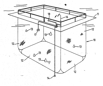
ferring~now;to~Fl e l:, a fish ~a ~ cage lO compr
floatlng~ rom;~w~ich are ~suspended~nets 12 formin~ an
enclosure~ Attached~to~th~e nèts:l2~for~ing the sides~and~bottom of~the
cagë.l0: ~sre ~a ~r~: of ~;~er~ b 11~:~13~,~ ge r ly ~t gh not~
atta~hed to~the:net~awsy:~:from~ ~ e~co ~ rs~o~ the~cage wher
ment~ to i ~ e~:of~t :n s will b ~ eatest.;~ so d
t~ i Y ~be ~ 3 i~-deteGted~by:~ e~or~more ~ e ~ ater detectors~
to~c ~ ~o ~ ~ cs~ whic ~m ~:co 'ently be~
25:~ o~ d~ ~ ~ w ~ ~fl.~A iw ~be:de-c i ~ lat r,:~;~the cag -mo ~ ~ed~
elec ~ des~ or d~ete lng~ pr ~ ~le ~so ce
he; ~A ~ : snd al80 ccmmon~c~elon~mssns for~
ng~ ~ a.l6.t~ Also~mo ~ ted~:~;on~;the.~n~ts:~ 12~ further~ls ` d~
30~ emitting~devices ~ t~ ~c ~ le of
edstors:,~ ch~;a ~;~;~8`'~
18:~to ~detect~ the~presence of;p-ople or~: ;
``U`de sr b~lls~such~ ~ose s ~ n at:~l3~1n Fi ~ re~l ~ e :~
ly ~mechsnic~i;dévices~whi~h~ e~activa
:distùrbed~by~a predstar~pushln6~into the net.~They will not be activated
water~current~!:or~ather:~movements~generated by the tides or westher.
~ SUBSTiTUTE SHEET ~
0 1
94~Q0007 P ~ /GB93/01319
-- 3 --
If a num~er of cages are located closP together it is possible to use
bells emitting sound at different frequencies on each cage so that it
is possible to ~etermine which cage is being disturbed.
The underwater detectors 14 may conveniently be hy~rophones,
positioned so as to detect sounds from the area around the cage lO. The
detectors may be responsive not only to the sounds emitted by the bells
13 but also to other sounds generated in the Area of the cages, such as
those made by boats. Thc physical location o~ the detectors 14 will
depend upon the area of covera~e required around the cage lO.
The ~urther sound-emitting devices used to scare away marine
:~ predators will preferably emit pulses of sound at frequencies and
intensities which are known to have the desired effect on the particular
~ przdators believed to constitute a threat to the stock in the cage.
It will be appreciated that the sound-emitting means 13 need
not be in the form of mechanical bells as has been described. Electronic
sound~emitting devices of many types will be suitable, so long as they
are able to operate in the marine environment. The use of such devices
will, however, normally require the addition of sume form of movement
~; detector to detect movement o~ the nets and cause the activation of the
sound-emi~ting devices~ themselves. One advantage of using such
:el~ctronic sound-emitting devices is that t~ey may ~lso be actuated by
o~her e~ects:than net movement. For example it is ~ossible to mount
~;; detectors on the walkw~y 11 to detect the presence of people or marine
creatures such ~s seals on the walkway when the system is activated,
thus~ detecting potential poachers. The discriminator means may be
arrange~ to ase such~presence of ~eop1e to operate~an alarm system to
the bàse station without triggeri~g the sound-em1tting devices, so that
; the apprehension of the~people is more likely.
The cage-mounted electronics 15 is preferab~y powered by an
i~ernaI bati~ery, as~it is likely that the location of the cage will
preclude the supply of power~through a cable. Battery charging devices
such ss a cage-mounted wind generator may be used, as may solar cells.
The electronics may simply 5ransmlt signals representing the detected
,
sounds to the base station &nd receive signals from the base station
representing the act1on to~be taken, such as the actuation of the seal-
:scaring devices. Alternatively, the cage-mounted electronics 15 may have
~ : : the ability to determine the threat posed by thé sounds detected and to
: ~ ~ :
SlJB~lTUTE SHEET
W 0 94/00007 ~13 9 101 P ~ ~GB93/013} ~ -
_ 4 _
cause the ~ppropriate action to be taken, signalling the base s~ation
~nly when the threat is one which needs to be drawn to the attention of
a base station operator. As well as transmitting signals to the base
station representing action being taken, the cage-mounted electronics
15 ~ay also tr~nsmi.t to the base station the actual sounds detected by ''
the hydrophones 14 so that a base station operator may de~ermine whether
further action is necessar~. The cage-mounted electronics will usually
be contained in a wàtertight tamper-proof container so that it is
. .
; protected~both from the~environment and from tampering by unauthorised
10 ~ persons.~
Figure 2 illustrate~s the~cage-mounted electronics 15 and the
base~station~20 in~schematlc manner~. me electronics 15 is represented
by~block 21, having~connected to it one or more~hydrophones 14 and one
or more sound-emitting devices~l7. Forming part o~the electronics,15
is~a radio tran~mitter-rec iver 22 connected to the antenna 16. In most
situations the radio~will'con~enl~ntly o~perate at ~ freguencies. The
electronics~lS~wiIl~ so~be c~ ~ ected~to~the battery charging system
'such~à`s~solar cells~Qr~wind generator ~ re~ady~mentioned and represent d
schèmatic~ly~at~23. In~addition to the so ~ d-emitting devices 17 the
20~ ;electro~'ics may~ ~ so~actuate flood lights 24 if $he perceived threat
warr ~ ts this action.
;1 ~ e base~station 20 is also sho~ in~Fi ~ re;2. ~ is includes
radio~receiver which receives the data transmitted by the cage-mo ~ ted
elèct~onics~ over~the~ radio ~li ~ . In addltion,~the base statlon may
`25~ `inclùde~a~10u~spe ~ er~ 5~so;~that~the base station operAtor may hear the
ac~tu ~ ~;soùnds~detect`ed;by~the~hydrophones 14~ nd a ksyboard~2
which ~instructions or responses m ~be e tered~in o;~he~system.
e~cage-mo ~ ted~electronics may conveniently include the
decision-making~me ~is which dete ~ ines the action to be taken in
, 30~ 'àc~ ~ nce with~the~Idènti~ication o~ a perceived~threat to he c~ge othe~,fish~stock~contsined~in~it.~This will~require~the~provision of some
fo~m~of~data~,~prQcessor~in~ the~ cage-mounted electronics 15 which is
pro6r ~ d ,to,,~res~ nd`~to~detected~ sound~to cause~ the~appropriste
response.~Alternatively, if~;the~purpose of the~cage-mounted electronics
`' 35~ is only~ o~transmit the~detected soùnd to~the base ststion and respondto~ins~tru-tions~received~'from~the~base station, then;the data processor
may~be~loGAted st~ the base station.
~ SUB~IITIJTESH~
~ 94/00007 h 13 ~1 U 1 P~/GB93/01319
In use9 the main purpose of the security system is to detect
and respond to attacks on the cage by msrine predators such as, but not
restricted to, seals. Since such attacks will involve the seals making
physical contact with the nets forming the c~ge, such attac~s will
actuate the underwater bells or other movement detectors 13. The sound
emitted by the sound-e~itting device~ will be detected by one or more
of the hydrophones 14, causing signals to be detected by the cage-
mounted electronics 15. It is difficult to detect the sounds of seals
or other marine predators in the water with any accuracy and hence the
provision of the und~rwater bells or other sound-~mitting devices is an
essentiaI feature of the security system. The sounds detected by the
hydrophones may be transmitted to the base station 20 over the radio
- link but will ~lso cause signals representing the actuation of the
sound-emit~ing devices to b applied to the data processor, which will
respond as programmed. If, for example, the signals detected by the
hydrophones indlcate tbat a single seal or a small number of seals is
~; ~aking unsuccessful attempts to penetrate the nets, then the system may
respond only by actuating the sound-emitting devices 17 to frighten the
; ~eals ~way. In this situation there may be no need to alert the basestation operator. If, on the other hand, the signals detected by the
hydrophones indicate a mass attack, an attack by a much larger predator
or the pre~ence of people on the walkway lI, the response ~ay be to
~ operate the sound-emitting devices and/or to warn the base-station
; ~ ~ operat~r.
5~ Non-~arine predators, generally human, may be able to attack
the stock held in a c~ge wlth~ut making physical contact with the nets
and actuating the underwater sound-emitting de~ices 13. However, the
hydrophones will be able to pick up the sound of their approach if by
boat and these sounds may be used to actuate the security system by
~; 30 themselves. The dsta processor may be programmed to respond to such
sounds by sending an alarm signal to the b~se station. The use of the
sound-emitting devices 17 may not be necessary since it unlikely that
these will afPect human predators. If the incident occurs at night then
he illumination of flood llghts will be use~ul but the call-out o~
personnel from the base station will be the most likely response. In
order to provide further information on an incident of this type the
miorophones 18 mounted on the floating platform will detect the sounds
~; S0BSTITUTE S~
W 0 94/00007 ~13~1 Vl PC~r/GB93/0131 ~
- 6
made by people on the pla~form, so that ~hese sounds may be transmitted
back to the b~se station for analysis by an operator.
The base station operator, to whom reference has been made
above, may be located at the base station or may be provided with a
5 paging device to warn when an incident occurs at the cage.
Alternatively, it is possible to incorporate in the base station a
telephone dialler which will call the operator by telephone and relay
`~ the signals received by the base station ~rom the cage.
It is not necessary for the com~unications link between the
cage and the b~se station to be by radio. If the cage is located close
to the shore or is, for example, in an inland lake or an inlet from the
sea, then cable links may be adequate. In either situation it may be
` ~ advisable to provide an alarm to indicate if the communication link has
been subjec~ to physical or other interference.
A single base station may be provided for a number of cages
each having its own sound-emitting de~ices, detectors, eleotronics and
90 on. As has already been suggested it is possible to provide each cage
with sound-emitting devices emitting sound of different frequencies so
that the cage-mounted electronics of one cage is not ~ctivated by sounds
20 ~r~m~ emitterB attached to an adjacent cage. Electronic filters may
provide~the neces~ary discrimination in thi~ si~uation.
; The cage- unted p~rts of the security system are ~ounted
in a~ hostile environment and it is advisable to include some form of
self-tes~tlng progr~m which is activ~ted from time to time to check that
25~ the integrity of the system has not been compromised. In the event of
a system~failure o~ any type sn appropriate message will be sent to the
base~station.~n ~ddi~ion, other features common to security systems of
other~ types; ay~be ~incorporated where these will provide a useful
output. The base station may be provided with some or all of the
30 per~pheral devLees shown in Figure 2, such as a printer 27D sound and
8ignal recording devices 28, a status display 29 or other appropri~te
; devices.
:: J
SUBSTITUTE SHEET